Allen-Bradley SLC 500 Manual
Hide thumbs
Also See for SLC 500:
- Reference manual (694 pages) ,
- Quick start manual (70 pages) ,
- Migration manual (60 pages)
Table of Contents
Quick Links
See also:
Instruction and Installation Manual
Allen-Bradley
Allen-Bradley SLC 500
Setup for using an A-B SLC 500
Use the following procedure to ensure your target device is setup properly for the Allen-Bradley SLC
500. The procedure is in condensed format. Only the required settings are outlined. For additional
details, see Creating a New Project beginning on page 3.
Project Setup
The drawing is a diagram of the Project Setup dialog box. Each button will display an additional dialog
box. Many settings are options and are not required to establish communications. Verify the Project
name and Display Device Model are correct. Leave the Initial Screen name blank.
Project name:
Project name appears in this field
Display Device
Model
Default Panel Name
Initial Screen
Screen Saver Timeout
Display
PLC & Protocols
PLC Type
Electrical Format
CN1
Serial Parameters
Port
PLC Type
Select the PLC type from the list box. (AB SLC DH485). See PLC Type on page 5.
QUICKDESIGNER
Project Setup
More
Model description appears in this field
Touch
Print
PLC Protocol name appears here
Protocol
System
OK
Cancel
Help
Project Notes
Disable Beeper
Print (Inactive)
PLC Protocol setup
Panel Trigger Tag
Watchdog Tag
Watchdog timeout
Allen-Bradley • • • • 11
Table of Contents

Related Manuals for Allen-Bradley SLC 500


Summary of Contents for Allen-Bradley SLC 500
- Page 1 Allen-Bradley SLC 500 Setup for using an A-B SLC 500 Use the following procedure to ensure your target device is setup properly for the Allen-Bradley SLC 500. The procedure is in condensed format. Only the required settings are outlined. For additional details, see Creating a New Project beginning on page 3.
-
Page 2: Baud Rate
Connecting to the SLC 500 A single point connection is simply one target display connected directly to the program port of a single SLC 500. This connection is made using the HMI-CAB-C83 cable. 12 • • • • Allen-Bradley QUICKDESIGNER... - Page 3 HMI-CAB-C83 Cable This cable connects the target display serial port to the Allen-Bradley SLC 500 Programming Port. 8-PIN MODULAR PHONE TO TCP DEVICE RJ-45 PROPRIETARY INFORMATION THIS INFORMATION IS PROVIDED AS A HMI-CAB-C83/A CONVENIENCE TO OUR CUSTOMERS. TO SLC 500...
- Page 4 HMI-CAB-C84 Cable This cable connects the target display serial port to the Allen-Bradley SLC 500 Programming Port. The cable is designed to allow connection to additional devices such as an Allen-Bradley 1747-PIC Interface Converter. Warning: The maximum length of this cable is 6 feet. Do not attempt to make it longer.
- Page 5 Channel 0 must be set up as a DH485 master. This configuration can only read/write variables in the local PLC. Since it is not dependent on network loading, this configuration will provide quick display updates. Allen-Bradley • • • • 15 QUICKDESIGNER...
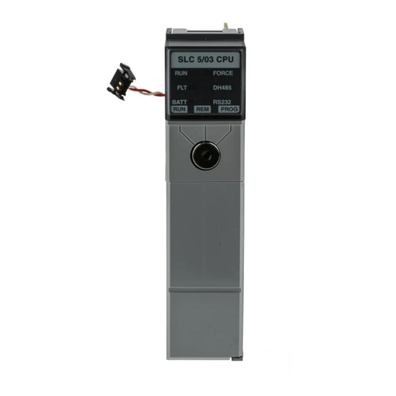
- Page 6 SLC 5/03 and SLC 5/04 DH485 Connections You can connect channel 0 of the SLC 5/03 and SLC 5/04 modules to the 1747-PIC to make a connection to the DH485 network. SLC 500 5/02 Modular Controller SLC5/04 Modular Controller SLC 5/04 CPU...
- Page 7 The drawing shows a possible configuration for DH+. QUICKPANEL PLC 5/15 SLC5/04 Modular Controller SLC 5/04 CPU FORCE BATT RS23 2 PROG DATA HIGHWAY PLUS MODULE LINE 2 BLUE SHIELD LINE 1 CLEAR Allen-Bradley • • • • 17 QUICKDESIGNER...
- Page 8 The Source ID is the target display node address and the Destination ID is the node address for the SLC. (See the "Setup for using an AB SLC 500 PLC" section for details about entering the source and destination ID's).
- Page 9 Note 4: Integer types (range –32768 to 32767) may be configured as unsigned (range 0 to 65535) Note 5: Node ID Max. is 254 for the SLC DF1 and 31 for the SLC 485. Allen-Bradley • • • • 19 QUICKDESIGNER...
- Page 10 This connects the termination impedance that is built into each link coupler as required by the DH-485 specification. 6 - TERM 5 - A 4 - B 3 - COMMON 2 - SHIELD 1 - CHS GND Allen-Bradley SLC 500 DF1 20 • • • • Allen-Bradley QUICKDESIGNER...
- Page 11 Setup for using an A-B SLC 500 DF1 Use the following procedure to ensure your target device is setup properly for the Allen-Bradley SLC 500 DF1. The procedure is in condensed format. Only the required settings are outlined. For additional details, see Creating a New Project beginning on page 3.
-
Page 12: Parity None Stop Bits
Click the Port button to display the Serial Parameters dialog. The port values are automatically set to standard default values. The following settings are recommended for AB SLC DF1. Elect. Format RS232 Baud Rate 9600 Data Bits Parity None Stop Bits Handshake None 22 • • • • Allen-Bradley QUICKDESIGNER... - Page 13 In this configuration, the MicroLogix 1000 is identical to the SLC500 DF1 protocol. To connect a QuickPanel to a MicroLogix 1000 PLC, use the SLC 500 DF1 protocol selection and an HMI-CAB-C106 cable. The drawing shows the setup dialog box for A-B SLC500 DF1.
-
Page 14: Table Of Contents
You can make your own cable using the following wiring diagram. PIN 7 PIN 6 PIN 8 PIN 4 PIN 5 PIN 3 TO TCP DEVICE TO PLC PORT PIN 1 PIN 2 HMI-CAB-C106 TO TCP DEVICE TO PLC PORT 24 • • • • Allen-Bradley QUICKDESIGNER... - Page 15 Click the Port button to display the Serial Parameters dialog. The port values are automatically set to standard default values. The following settings are recommended for AB SLC DH485. Elect. Format RS232 Baud Rate 19200 Data Bits Parity Even Stop Bits Handshake None Allen-Bradley • • • • 25 QUICKDESIGNER...
- Page 16 485 network on the AIC Port 3 using the HMI-CAB-C117 cable. MicroLogix QUICKPANEL PORT 3 DH485/DF1 PORT 2 MASTER-SLAVE MINI-DIN 8 RS-232 1761-CBL-AM00 1761-CBL-HM02 HMI-CAB-C117 AUTO 19200 AIC+ 1200 14400 2400 9600 4800 PORT 1 1747-CP3 DB-9 RS-232, DTE 1761-CBL-AC00 26 • • • • Allen-Bradley QUICKDESIGNER...
- Page 17 1761-CBL-PM02 QUICKPANEL 1761-CBL-AP00 FOR MICROLOGIX 1000 (SERIES C OR HIGHER) AUTO 19200 AIC+ 1200 14400 2400 9600 4800 HMI-CAB-C106 1747-CP3 1761-CBL-AC00 PORT 1 FOR SLC5/03 OR SLC 5/04 DB-9 RS-232, DTE CHANNEL 0 Allen-Bradley • • • • 27 QUICKDESIGNER...
- Page 18 The AIC+ can connect a QuickPanel through the Port 3 DH-485/DF1 Phoenix Plug using the HMI- CAB-C117 cable. To Terminal B To Terminal A To Terminal COM TO AIC+ TO TCP DEVICE To Terminal SHIELD HMI-CAB-C117 28 • • • • Allen-Bradley QUICKDESIGNER...
- Page 19 Note 4: Integer types (range –32768 to 32767) may be configured as unsigned (range 0 to 65535) Note 5: Node ID Max. is 254 for the SLC DF1 and 31 for the SLC 485. Allen-Bradley • • • • 29 QUICKDESIGNER...
- Page 20 Connecting to a PLC-2 Program Port HMI-CAB-C90 This cable is used to connect the target display to an Allen-Bradley PLC-2 PLC. A label is placed on each end of the cable to indicate which device should be connected to that end.
- Page 21 Setup for using an A-B PLC-2 Program Port Use the following procedure to ensure your target device is setup properly for the Allen-Bradley PLC2. The procedure is in condensed format. Only the required settings are outlined. For additional details, see Creating a New Project beginning on page 3.
- Page 22 17 16 15 14 13 12 11 10 7 6 5 4 3 2 1 0 0 1 0 Reading this variable would result in the value 21845 because this is the decimal equivalent of the binary value shown in the example. 32 • • • • Allen-Bradley QUICKDESIGNER...
- Page 23 BCD value of 5. Note that although the data in the word was the same as used in the WUB example, the result obtained by reading the value as a WSD variable is not. Allen-Bradley • • • • 33 QUICKDESIGNER...
- Page 24 2525 or 1365 decimal. Note that although the data in the word was the same as used in the WUB and WSD examples, the result obtained by reading the value as a WSO variable is not. 34 • • • • Allen-Bradley QUICKDESIGNER...
- Page 25 PLC data word. The format of a MSG word is shown below. 17 16 15 14 13 12 11 10 7 6 5 4 3 2 1 0 First ASCII Byte Second ASCII Byte Allen-Bradley • • • • 35 QUICKDESIGNER...
- Page 26 -999 to 999. However, when you change the decimal position from 0 to 1, 2, or 3 in the data format dialog box, your available range decreases accordingly. For example, if you set the decimal position to 3, your range changes from -.999 to .999. 36 • • • • Allen-Bradley QUICKDESIGNER...
- Page 27 The choice of addresses on the Data Highway greatly influences its speed of operation. Be sure to read the Allen-Bradley documentation on the Data Highway, particularly those sections pertaining to selection of module addresses and the polling scheme used on the Data Highway. In general, it is a good practice to number Data Highway addresses consecutively.
- Page 28 HMI-CAB-C53/A RS232 Cable This cable is used to connect the target display to Channel 0 on an Allen-Bradley PLC-5/30 PLC. A label is placed on each end of the cable to indicate which device should be connected to that end.
- Page 29 You can make your own cable using the following wiring diagram. Setup for using an AB PLC5 DF1 Use the following procedure to ensure your target device is setup properly for the Allen-Bradley PLC5 DF1. The procedure is in condensed format. Only the required settings are outlined. For additional details, see Creating a New Project beginning on page 3.
- Page 30 (AB PLC5 DF1) Elect. Format RS232 Baud Rate 9600 Data Bits Parity None Stop Bits Handshake None Protocol Button Click the Protocol button to display the dialog box associated with the selected PLC. 40 • • • • Allen-Bradley QUICKDESIGNER...
- Page 31 Just as a reminder, when working with Full Duplex, you have to set up the PLC Channel 0 to Point-to- Point. For Half Duplex, Channel 0 must be set to System (Slave). Allen-Bradley • • • • 41 QUICKDESIGNER...
- Page 32 Module. Some models of the PLC-5, such as the PLC-5/30, have a DF1 port that can be used for direct connection to the target display. (See PLC-5 DF1 in a previous section.) The following drawing illustrates a connection between a target display, a 1785-KE Module and a Data Highway Plus link. 42 • • • • Allen-Bradley QUICKDESIGNER...
- Page 33 The following drawing shows a QUICKPANEL connected to two PLC-5 processors on a Data Highway Plus network. QUICKPANEL PROCESSOR 2 PROCESSOR 1 DATA HIGHWAY PLUS MODULE LINE 2 BLUE SHIELD LINE 1 CLEAR Allen-Bradley • • • • 43 QUICKDESIGNER...
- Page 34 Enter the Source ID (target display address). Enter the Destination ID (PLC address). Note that the Source ID and Destination ID are in octal. Enter Timeout in seconds. Click OK to return to the Project Setup dialog box. 44 • • • • Allen-Bradley QUICKDESIGNER...
- Page 35 The serial port on the target display is connected to the KE module with the HMI-CAB-C55 cable. TO A-B KE TO TCP DEVICE SHIELD DATA HIGHWAY TO TCP DEVICE HMI-CAB-C55 TO PLC PORT Set the dipswitches on the KE module as follows: Allen-Bradley • • • • 45 QUICKDESIGNER...
- Page 36 Parity = None (Recommended) Open (off) Disable embedded responses Open (off) Defeat RS232 handshake on computer port Open (off) Accept all messages Open (off) Use full duplex protocol Open (off) Pass through diagnostic commands 46 • • • • Allen-Bradley QUICKDESIGNER...
- Page 37 (Add a leading 'o' to the bit addres to designate octal address. EX: I1:2/o17 is the same as I1:2/15). 0 - 15 Decimal for all other file types optional 0 - 15,999 Decimal for bit type files when not specifying the element number. Bit Addresses: Allen-Bradley • • • • 47 QUICKDESIGNER...
- Page 38 -32768 to +32767 0-377 (octal) /0 - /17 -32768 to +32767 S2:00 0-999 /0 - /15 Y (5) -32768 to +32767 or S: B3:000 0-999 /0 - /15 -32768 to +32767 or Bn:000 48 • • • • Allen-Bradley QUICKDESIGNER...
- Page 39 Note 5: These are system variables. Use caution when writing to S variable types. Note 6: O and I bits can use octal addressing by adding 'o' to the bit address. EX: I1:2/o17. Note 7: Default format for I/O is Octal words and Decimal Bits Allen-Bradley • • • • 49 QUICKDESIGNER...
-
Page 40: This Cable Is Used To Connect The Target Display To A Micrologix
In this configuration, the MicroLogix 1000 is identical to the SLC500 DF1 protocol. To connect a QuickPanel to a MicroLogix 1000 PLC, use the SLC 500 DF1 protocol selection and an HMI-CAB-C106 cable. The drawing shows the setup dialog box for A-B SLC500 DF1. - Page 41 -32768 to 32767 0-999.DN 0-999.EN 0-999.ER 0-999.UL 0-999.IN 0-999.FD N7:000 or n:=10-255 0-999 -32768 to 32767 Nn:000 /0 - /15 A12 or An: n:=8-999 1-9999 ASCII F8 or Fn: n:=8-999 0-9999 0-9999 1-9999 0-65535 Allen-Bradley • • • • 51 QUICKDESIGNER...
- Page 42 Setup for A-B Remote I/O Use the following procedure to ensure your target device is setup properly for the Allen-Bradley RIO. The procedure is in condensed format. Only the required settings are outlined. For additional details, see Creating a New Project beginning on page 3.
- Page 43 201 Remote I/O modules. If the box is not checked, all data values will be set to 0 when power is cycled. Before you click any more buttons or check boxes, read the sections concerning Observation mode and Emulation mode. Allen-Bradley • • • • 53 QUICKDESIGNER...
-
Page 44: Word
I/O transfers on the Remote I/O link. An Allen-Bradley rack corresponds to 128 input bits and 128 output bits of defined PLC data table memory. In the PLC memory, a 'data table' sets aside 128 bits for input and 128 bits for output. This data table allows the PLC to communicate with other devices. - Page 45 I/O data on the link, including the data sent and received by the scanner in rack 1. For this example, there is an unused quarter rack at Rack 1, Group 2 and 3. The display device will emulate the unused quarter rack. Allen-Bradley • • • • 55 QUICKDESIGNER...
- Page 46 Rack 1, Group 2 and 3. This will allow you to design panels with discrete I/O. You can have 32 input and 32 output devices on each quarter rack. The following diagram shows how hardware rack addresses are converted into variable names. 56 • • • • Allen-Bradley QUICKDESIGNER...
- Page 47 Group 2, slot 0. The naming scheme will help you remember the racks that are in emulation mode. See the following example. Click the OK button to accept the Tag Name. The check box now appears with a check mark inside, indicating it has been checked. Allen-Bradley • • • • 57 QUICKDESIGNER...
- Page 48 BTW box in the same slot will be checked. Click the Auto name checkbox and the Tag Name will appear as BTW0120. Click the OK button and observe that both check boxes in Slot 0 are checked and both are set to transfer 16 words. 58 • • • • Allen-Bradley QUICKDESIGNER...
- Page 49 • select the Tag Name or click Auto name • select the desired number of words • click OK. Verify the Tag names, transfer mode and number of words. • click OK. Done! Allen-Bradley • • • • 59 QUICKDESIGNER...
- Page 50 The following drawing shows how a Block Transfer Read function in the PLC reads data from the BTR0120 file in the target display. Since the Length was set to 16, there will be 16 words read from the target display into the PLC. 60 • • • • Allen-Bradley QUICKDESIGNER...
- Page 51 Data Display. For example, when creating a numeric data display, you are presented with a setting menu that requests a Tag name. If you entered BTW0120[7], the target display would read word 7 from the data file labeled BTW0120 and display it in a numeric field. Allen-Bradley • • • • 61 QUICKDESIGNER...
- Page 52 Data Entry. For example, when creating a numeric data entry, you are presented with a setting menu that requests a Tag name. If you entered BTR0120[2], the target display would write the data entered from the data entry panel to word 2 in the data file labeled BTR0120. 62 • • • • Allen-Bradley QUICKDESIGNER...
- Page 53 If you entered BTR0120[7]/04, the target display would write bit 4 of word 7 in the data file labeled BTR0120. Block Transfer Tag Name Summary The format for block transfer tag names is described below. Allen-Bradley • • • • 63 QUICKDESIGNER...
- Page 54 (02:CD) Com error, undefined (02:CE) Com error, undefined (02:CF) Com error, Timeout (also fe & ff) (02:FB) Data memory table overflow (02:FC) Protocol error (02:FD) Data error (02:FE) RX timeout (02:FF) TX timeout or SIO error 64 • • • • Allen-Bradley QUICKDESIGNER...
- Page 55 Pass Through Mode QUICKDESIGNER Advanced supports the downloading of application files over the Allen-Bradley Data Highway +, using the PLC-5 Remote I/O Pass-Through feature. The QuickPanel (QP2) is connected as a remote I/O device to the PLC-5. This feature allows the customer to download application files to the QuickPanel without changing cabling, and without having to go from QuickPanel to QuickPanel with a personal computer for direct downloading.
- Page 56 Group 3, has been selected for emulation. Slot 0 has been configured for a BTR of 64 and a BTW of 64. Click the Pass-through button to display the Pass Through dialog box. 66 • • • • Allen-Bradley QUICKDESIGNER...
- Page 57 ;BoardAddress, this is a hexadecimal #, address segment of the SD2 card. BoardAddress=C800 (see CONFIG.SYS section to configure this address) ;IOport, this is a hexadecimal #, IO port required by the SD2 card. Allen-Bradley • • • • 67 QUICKDESIGNER...
- Page 58 To upgrade or reload the device executable, you must use serial download. Critical faults during a download may require a new device executable file and application file be loaded into the display using serial download. 68 • • • • Allen-Bradley QUICKDESIGNER...
- Page 59 Aromat Aromat FP1 (MEWNET) Do NOT use this protocol with QP1 devices. It is designed to be used with CAUTION ONLY QP2 devices. For example, QPJ-2D100-L2P is a QP2 device. Tag Variable Table Name Address range Value range Writeable Type 0-999, 0-65535, integer...
- Page 60 Cable This cable connects to a FP1 Smart Cable P/N AFP15201-US9. The FP1 Smart Cable can be obtained from Aromat. TO TCP DEVICE TO PLC PORT Shield HMI-CAB-C111 70 • • • • Aromat QUICKDESIGNER...
- Page 61 ASCII Protocol Single Drop Single Drop protocol extends the functionality of the QUICKPANEL family by allowing a host device access to the target display memory. Single Drop is an ASCII communication protocol that allows panel triggering, reading and writing variables, and setting the time and date. A host device can be a computer, embedded controller, ASCII Module, BASIC Module, or any device capable of sending and receiving ASCII character strings.
- Page 62 Project Setup The drawing is a diagram of the Project Setup dialog box. Each button will display an additional dialog box. Many settings are options and are not required to establish communications. Verify the Project name and Display Device Model are correct. Leave the Initial Screen name blank. Project Setup Project Notes Project name:...
- Page 63 Internal Tags The ASCII protocol requires using internal tag variables. You must create a contiguous block of internal tag variables using the name DMxxxx, where xxxx is a four digit count from 0001 to 9999. These tag variables are assigned to the various operators used on the panels. For example, a pilot light tag variable name might be DM0002.
- Page 64 The first part of the BASIC statement is CHR$(20). The ASCII character 20 is equivalent to a CONTROL-T. The next section of code is the character 8, which is the panel ID number. The last section of the code string is CHR$(13). The ASCII character 13 is equivalent to a CARRIAGE RETURN.
- Page 65 If you typed the command string from an ASCII terminal, this is the response from the target display. Note the zero value between the value 43 and 24. ⇑12,43,,24. The following example is a BASIC statement that will read 4 variables, beginning with variable ID 1. PRINT#1,CHR$(18);1;",";4;CHR$(13) The first part of the BASIC statement is CHR$(18).
- Page 66 Writing Text Characters The Text Display operator is used to display text characters or messages. The tag variable selected for the Text Display operator MUST be changed to a STRING type. Set the SIZE to the number of characters for the Text Display buffer. If you want to display 20 characters, set SIZE to 20.
- Page 67 Example The following example uses common panel tools and a terminal emulation program to demonstrate ASCII protocol. Start by creating a new project and selecting a display type. Project Setup Dialog Box Many settings are options and are not required to establish communications. Make sure you have selected the correct Display Device model.
- Page 68 Protocol Button Click the Protocol button to display the ASCII Single Drop dialog box. The timeout shown works for most applications. System Button Make sure you select QPJ-1 or QPJ-2 for compilation. For more information about creating a new project and configuring the display, see page 3. Please note that some features are available only on the QP2.
- Page 69 The following table is a list panel components and internal tags which are used in the examples of the ASCII protocol. Panel Type Tag Name ID Number Tag Type Bytes Data Push Button DM0001 0001 Integer Circular, Toggle Pilot Light DM0001 0001 Integer...
- Page 70 The terminal program has several Settings that are used to establish communications. Here is a list of the settings used for this example. Settings: Terminal Emulation: VT100 Function Keys: LEVEL1 RD DM0001 ^R1,1^M RD DM0002 ^R2,1^M WT 03=1 ^V3,1^M WT 03=0 ^V3,0^M WT 04=2 ^V4,2^M...
- Page 71 Example: ^R2,1^M (Level 1, F2) Explanation: Read 1 Tag starting with tag 2. Tag 2 is DM0002, which is assigned to the Word Button. The initial reading of the Word Button should be 0. Data returned from the display: ^R0^M Note: Press the Word button on the display and watch the Data Display assigned to the Word Button increment by 5.
- Page 72 Example: ^V5,0^M (Level 1, F8) Results: Setting Tag 5 to a value of 0 will cause the Numeric Display to show 0. Example: ^V7,TOTAL^M (Level 2, F3) Explanation: Write to Tag 7 the text characters "TOTAL." Tag 7 is DM0007, which is assigned to a Text Display.
- Page 73 Reading and Writing Multiple Tags You can save communication time by sending a command to read/write more than one tag. The format for a read command looks like this: Format: (^R)(Variable ID number)(,) (Count) (^M) The 'Count' portion of the protocol can be set to allow reading multiple tags. There are some restrictions for writing.
- Page 74 Error Messages Error messages appear on the bottom of the QP2 display. Errors encountered with QP1 are ignored and the message is discarded. Error Messages Meaning PLC COM. ERROR(02: D0 ) Month out of Range PLC COM. ERROR(02: D1 ) The month was not sent when sending the date PLC COM.
- Page 75 B&R MCCP30, MCCP31, MCCP32 Connecting a target display to a B&R Minicontrol B&R QUICKPANEL jr. NT/PS DC out OK STATU S TO B&R B&R MINICONTROL Serial TO TCP DEVICE Interface n.c. HMI-CAB-C98 HMI-CAB-C98 Cable The HMI-CAB-C98 cable has two wires; one marked 0 and the other marked 1. Make sure the wire marked 0 connects to the 0 terminal and the wire marked 1 connects to the 1 terminal.
-
Page 76: Handshake None
Setup for using a B&R Minicontrol Use the following procedure to ensure your target device is setup properly for the B&R Minicontrol PLC. The procedure is in condensed format. Only the required settings are outlined. For additional details, see Creating a New Project beginning on page 3. Project Setup The drawing is a diagram of the Project Setup dialog box. - Page 77 Protocol Button Click the Protocol button to display the dialog box associated with the selected PLC. Enter the Destination ID (PLC address). Enter Timeout in seconds. Click OK to return to the Project Setup dialog box. B&R Tag Variable Table Format: R[A][F]{L}{.#}{_#} A - address ( 0 - 7167 in bytes) F - format...
- Page 78 CANopen CAN is a serial bus system especially suited for networking "intelligent" devices as well as sensors and actuators within a system or sub-system. CAN is a serial bus system with multi-master capabilities, that is, all CAN nodes are able to transmit data and several CAN nodes can request the bus simultaneously.
- Page 79 Configure I/O Click the Configure I/O button to display the following dialog box. Inputs Enter the number of Input words up to a maximum of 127 words (254 bytes). The Start Address is normally set to 0. You can change the Start Address to create an offset address. Different devices can reference the same CANopen address but may require an offset for one of the devices.
- Page 80 Double Word Storage Format This option allows selecting the way words are arranged into double words. Selecting MSW-LSW will arrange words from the MSW (Most Significant Word) to the LSW (Least Significant Word). Selecting LSW-MSW will arrange words from the LSW (Least Significant Word) to the MSW (Most Significant Word).
- Page 81 The number of Input and Output words selected will determine the valid address range limits for each variable type. The variable type names are fixed and are displayed in a cell corresponding to the addressing type. For example, in the following dialog box, the number of Input Words is set to 64. The variable name for Input Words is IW and the range for 64 words is IW0 to IW63.
- Page 82 A byte is 8 bits, therefore the addressing method is to use a period as the bit delimiter in the addressing format. For example, I0.0 is bit 0 of Word 0, and I0.7 is bit 7 of Word 0. Setup Network Click the Setup Network button to display the following dialog.
- Page 83 Tag Variables Valid tag variable names and address ranges are shown in the CANopen Protocol dialog box when you configure the protocol. The number of Input and Output words and the addressing will determine the valid address range limits for each variable type. The variable type names are fixed and are displayed in a cell corresponding to the addressing type.
- Page 84 For the combination of a W, DW, W, the following example shows the layout. BYTE BYTE Word Addressing Word Addressing: Input Words = 127, Output Words = 127, Input start address = 0, Output start address = 0. Name Address range Value range Write Type...
-
Page 85: Table Of Contents
For the combination of a W, DW, W, the following example shows the layout. WORD WORD Examples Format Example Byte Addressing Description Word Addressing Description Iaa.b ** I37.7 Input bit 7 of byte 37 (LSB of Input bit 7 of word 37 word 18) Qaa.b ** Q37.7... - Page 86 PLC Comm Errors In the event of a communication problem, error messages are displayed on a status line at the bottom of the display. Error Displayed Definition PLC COMM ERROR (02:C0) Detected wrong or missing I/O card PLC COMM ERROR (02:C1) I/O card failed to initialize and start PLC COMM ERROR (02:C2) Invalid configuration, must match master...
- Page 87 DeviceNet Protocol Setup The Project Setup dialog box can be displayed by clicking the Setup button in the main menu. In the Project Setup dialog box, go to the PLC &Protocols section. Select DeviceNet from the PLC Type list box. Click the Protocol button to display the following dialog box. Configure I/O Click the Configure I/O button to display the following dialog box.
- Page 88 Inputs Enter the number of Input words up to a maximum of 127 words (254 bytes). The Start Address is normally set to 0. You can change the Start Address to create an offset address. Different devices can reference the same DeviceNet address but may require an offset for one of the devices. Changing the Start Address will change the address ranges shown in the DeviceNet Protocol dialog box.
- Page 89 Word Addressing In this configuration example, Input Words are set to 64, Output Words are set to 64 and Addressing is set to Word Boundaries. When the OK button is clicked, the following DeviceNet Protocol dialog box will appear. The valid address ranges are shown for all types of variables.
- Page 90 Byte Addressing In this configuration example, Input Words are set to 64, Output Words are set to 64 and Addressing is set to Byte Boundaries. When the OK button is clicked, the following DeviceNet Protocol dialog box will appear. The valid address ranges are shown for all types of variables.
- Page 91 Setup Network Click the Setup Network button to display the following dialog. Select the Node Address from the list box. You can choose the DIP Switch on the Device Net module or an address from the list. Select the Data Rate from the list box. You can choose to use the DIP Switch on the DeviceNet module or force the data rate to 125, 250 and 500 Kbaud.
- Page 92 Byte Addressing Layout DWORD BYTE WORD DWORD BYTE WORD ID250 QD250 IB250 QB250 IB251 QB251 IB252 QB252 IW252 QW252 IB253 QB253 For the combination of a W, DW, W, the following example shows the layout. BYTE BYTE Word Addressing Example Input Words = 127, Output Words = 127, Input start address = 0, Output start address = 0.
-
Page 93: Input Byte At Byte 37 (Lsb Of Word
Word Addressing Layout DWORD WORD DWORD WORD IW125 QW125 ID125 QD125 IW126 QW126 For the combination of a W, DW, W, the following example shows the layout. WORD WORD More Examples Format Example Byte Addressing Description Word Addressing Description Iaa.b ** I37.7 Input bit 7 of byte 37 (LSB of word 18) - Page 94 Error Codes In the event of a communication problem, error messages are displayed on a status line at the bottom of the display. 02:FF:A0 Error initializing Anybus module 02:FF:01 Incorrect Anybus module ID 02:FF:02 Anybus module watchdog time-out (module lockup) 02:FF:03 Network Error - Network not connected 02:FF:10...
- Page 95 ASCII Flex Protocol The ASCII Flex Protocol is designed to allow intelligent controllers to communicate with Quick Panels. In the world of Programmable Logic Controllers (PLC), the protocol is nearly invisible to the user. For example, when a pilot light is placed on a panel, a variable is assigned to it. The variable is the name of a register in the PLC.
- Page 96 If on the other hand, you select Flex as your protocol and then immediately go into the Flex dialogs and create Sequences and tags, you will really be sad when nothing works. It looks like Edit/New sequence dialogs stop you from creating tags at this point. However, you will have no idea why the tags you are entering aren't being accepted.
- Page 97 The Push Button is a Momentary button with the tag variable assigned to RL1. One Numeric Data Display is assigned to RL2 and the other to RL3. A Text display was assigned to RA1 for Invalid Messages and another Text display was assigned to RA2 for Error Messages. The registers for Invalid Messages and Error Messages are entered in Setup.
- Page 98 Edit Sequence The Edit Sequences dialog box shows a list of all Solicited and Unsolicited sequences. Click on any sequence to Edit or Delete it. Click the New button to create the sequences for the demo. The first sequence is Data Display. Note that this sequence has a Send and Receive command.
- Page 99 The last sequence is another Data Display. Note that the Command Type starts with a Receive and ends with a Send command. The register RL3 will not be updated automatically but will change when the terminal sends a Command String in the format specified by the Receive Command String. If the received command string is valid, the Send command sends out a Command String.
- Page 100 The next association is for RL1, which is assigned to the Push Button. RL1 is associated with the sequence Push Button #1 for a Button Press. When the push button is pressed, the sequence defined by Push Button #1 is executed. The sequence sends out a command string. Note: It is recommended that you use the Register Long (RLxxxx) register with a Momentary Push Button.
- Page 101 Hardware Connection There are two methods used to connect a QuickPanel display to an intelligent controller or terminal. Go to Project Setup and click the Port button. The choices for Handshake are None and Xon/off. Use the Hardware Handshake cable with the None option when the Controller or PLC uses the hardware handshaking lines to control the communications.
- Page 102 The Function keys were setup to send specific command strings. The setup is shown below. Pressing the F1 key will send the string "Rec Data 123 ^M." The format must be "Rec Data " because this was specified for the Data Display sequence. The number following the "Rec Data " string will become the data stored in RL2.
- Page 103 Global Parameters The following parameter are global which can be set in the Setup. Does Controller Echo Commands Does Controller Echo Commands is a character data entry field which will except a Y or N character. Some terminal protocols echo the characters being sent to the controller back to the Quick Panel. Set the option to Y if the controller sends an echo and N if it does not send an echo.
- Page 104 Error Message Destination Error Message Destination from figure 1 is a data entry field which will only take a DM register as valid data. This DM register will be setup up as a text field. Internal Error Messages will be placed in the DM register.
-
Page 105: Byte
Edit Sequences The Edit Sequences dialog box will list all the Solicited and Unsolicited sequences. You can create a new sequence, edit existing sequences or delete a sequence. New Sequence This dialog box allows creating new sequences. (This is the same dialog box for editing sequences). Sequence Name This is a unique name used to identify the sequence. - Page 106 Send Command The main purpose of a Send Command is transmit commands to a controller. A Send Command can contain the following components: String Literals, Embedded Register Fields, and Byte Literals. For example: {RF22 \*Prec 5}\13\10 is a command string. String Literal: Elements of a string command that is not an embedded register or a Byte Literal.
- Page 107 Associate Registers The Associate Sequences dialog box is used to associate sequences with registers. Poll The Poll table will enable the user to associate the Sequence Names with Rx registers. The result of this association will enable the operating system to execute a Sequence when a read of a particular register is done.
- Page 108 These are limited only by the amount of memory available. Later in this document I will provide a Formula for calculating the amount of memory used. Memory Used Status Bar This indicator is shown on 3 of the Flex dialogs. It represents the percentage of memory used by the project.
- Page 109 Tag Table This is the syntax for normal tag creation via the Tag Editor or assignment to a Panel Object. There are three tags. RAxxxx Register Ascii RLxxxx Register Long RFxxxx Register Float Examples: RA1000 RF1001 \* Prec 2 RL9999 RL44 In the examples above, the ‘xxxx’...
- Page 110 To embed a carriage return/line feed you would add the following to your string command. \13\10. Remember that the ‘xxx’ is in decimal, not hexadecimal. String Literals String literals is everything else in the string command that is not an embedded register and not a Byte Literal.
- Page 111 Total Bytes Used = T1 + T2 + T3 Error Messages Below is a list of the Error numbers and Error messages which can be displayed in the ASCII Flex Protocol. Following each Error Message is a more descriptive explanation of the error. Error #: 02:87 Error Msg ERROR 02:87 Prompted Send Failed because no Prompt was defined Explanation: A Prompted Send was executed but, no prompt was defined so it failed.
- Page 112 Explanation: (Compiler Error ) The length was less than 5 when it should have been at least 5. Error #: 02:90 Error Msg ERROR 02:90 The length for the Rx Long in a Send Command was invalid Explanation (Compiler Error ) The length was not equal to 4. Error #: 02:91 Error Msg ERROR 02:91 The length for the Rx Float in a Send Command was invalid Explanation: (Compiler Error ) The length was less then 4.
- Page 113 Explanation: (Compiler Error ) The length was not equal to 4. Error #: 02:9B Error Msg ERROR 02:9B No digit or . found for the Rx Float in a Receive command Explanation: A Receive Command was being executed, it was expecting numeric data or a ‘.’ from the controller but data was not numeric.
- Page 114 Error #: 02:A5 Error Msg ERROR 02:A5 There was more then 10k words to allocate for the Rx table Explanation: The Quick Panel can only dynamically allocate 10 thousand WORDs or 20 thousands bytes for the Rx table. To many local registers have been created. Error #: 02:A6 Error Msg ERROR 02:A6 The packet received was to large Explanation: A packet was received which was larger then the Receive Buffer.
- Page 115 Error #: 02:AE Error Msg ERROR 02:AE Could not transmit because all of the echoes were not received Explanation: The driver when in echo mode is suppose to echo all the characters it receives. If the driver wants to transmit a string and it did not receives all the characters echoed from an earlier sent command it will wait the time-out period for the echo of all the characters.
- Page 116 Mitsubishi Overview This section describes the operation of a target display with the Mitsubishi series Programmable Logic Controllers. You should be familiar with Mitsubishi products before attempting to connect a target display. The Mitsubishi MELSEC-A and FX series are supported. Mitsubishi A Series The target display can communicate with a Mitsubishi processor using the AJ71C24 Computer Interface Module in a A1CPU, A2CPU and A3CPU.
- Page 117 Project Setup The drawing is a diagram of the Project Setup dialog box. Each button will display an additional dialog box. Many settings are options and are not required to establish communications. Verify the Project name and Display Device Model are correct. Leave the Initial Screen name blank. Project Setup Project Notes Project name:...
- Page 118 Click OK to return to the Project Setup dialog box. Setting the Mitsubishi Transmission Control Protocol The Mitsubishi Computer Interface Module has multiple protocols available by changing the position of the MODE switch. The target display uses Format 1 which is selected as position 1 for RS232 and position 5 for RS422.
- Page 119 RS422 Cable Drawing The following drawing is for an RS422 cable. -RCV TXB- TXA+ +RCV RXB- -XMT RXA+ +XMT QUICKPANEL MITSUBISHI Mitsubishi A1S Computer Link Module Use the following cable for the A1S Link Module. TO TCP DEVICE TO PLC PORT HMI-CAB-C88 Mitsubishi Tag Variable Names, A Series PLC Name...
- Page 120 Mitsubishi FX Series Connecting to a Mitsubishi FX QUICKPANEL jr. MITSUBISHI FX TO MITSUBISHI PROGRAM PORT FX-16MR POWER BATT.V PROS-E / CPU-E MITSUBISHI TO TCP DEVICE HMI-CAB-C91 HMI-CAB-C91/B Cable RXA+ TO PLC PORT CTSB DTRB TO TCP DEVICE CTSA DTRA HMI-CAB-C91/B SHIELD The Mitsubishi FX ON has a mini DIN connector for the program port.
- Page 121 Project Setup The drawing is a diagram of the Project Setup dialog box. Each button will display an additional dialog box. Many settings are options and are not required to establish communications. Verify the Project name and Display Device Model are correct. Leave the Initial Screen name blank. Project Setup Project Notes Project name:...
- Page 122 Mitsubishi FX Tag Variable Table PLC Name Word Write Value Range Operator Range 0-511 0-65535 PB, SS, PL, IPB 0-255 0-32767 PB, SS, PL, IPB 0-199 0-32767 PB, SS, PL, IPB C200 200-255 32-bit unsigned PB, SS, PL, IPB Counter 0-177 1-bit Input, 0-1 0-177...
- Page 123 Mitsubishi Program Port Mitsubishi MELSEC-A Program Port The drawing shows the setup dialog box for Mitsubishi MELSEC-A Program Port. The default setting for Timeout is correct for most applications. Serial Port Parameters for the Display Click the Port button to display the Serial Parameters dialog. The following settings are recommended for Mitsubishi MELSEC-A Program Port.
- Page 124 RXA+ TO PLC PORT CTSB DTRB TO TCP DEVICE CTSA DTRA HMI-CAB-C91/B SHIELD Tag Variable Table Name Address range Value range Writeable Type 0-1023 0-65535 integer 0-255 0-65535 integer 0-255 0-65535 integer 0-3FF 0-65535 integer 0-8191 0-65535 integer 0-7FF integer 0-7FF integer 0-2047...
- Page 125 Modicon Modicon Modbus Modicon 884 or 984A, B, or X Processor To connect a target display to a Modicon 884, 984 A, B, or X, or other 25 pin Modbus Port, use an HMI-CAB-C53 cable, connected as shown below. Make sure you connect the target display to the end marked TO TCP DEVICE and connect the Modicon PLC to the end marked TO PLC PORT.
- Page 126 Modicon Slot Mount 984 PLC (9-pin Modbus Port) Connecting a Modicon Slot Mount 984 PLC To connect a target display to a Modicon Slot Mount 984 PLC, use an HMI-CAB-C58 cable, connected as shown below. HMI-CAB-C58/A Cable This cable is used to connect the target display to a Modicon Slot Mount 984 PLC. TO PLC PORT TO TCP DEVICE SHIELD...
- Page 127 HMI-CAB-C102/A Cable This cable is used to connect the target display to a Modicon 984 Micro PLC. 8-PIN MODULAR SHIELD TO TCP DEVICE SHIELD PHONE RJ-45 RJ-45 TO MODICON MICRO PLC HMI-CAB-C102/A 25-PIN MALE Setup for using an 884 or 984 PLC Use the following procedure to ensure your target device is setup properly for the Modicon Modbus PLC.
- Page 128 Port Button Click the Port button to display the Serial Parameters dialog. The port values are automatically set to standard default values. See Serial Parameters on page 6. The following settings are recommended for Modicon Modbus Elect. Format RS232 Baud Rate 9600 Data Bits Parity...
- Page 129 Tag Variable Table This protocol supports Multi-Drop and RS422/485 Half Duplex. Some Modicon systems use multiple processors connected together. You can address a slave by adding an underscore and the slave address to the variable name. For example, OD0001 is read from the Source ID station address while OD0001_3 is read from slave address 3.
- Page 130 IRaaaaa Input register ORaaaaa Output register OSaaaaa Output register, Signed ONaaaaa Output register, Negitive MSaaaaa Output register, Text DRaaaaa Output register, Double LUaaaaa Output register, Long LSaaaaa Output register, Long, Signed FRaaaaa Output register, Float ILUaaaaa Input register, Long ILSaaaaa Input register, Long, Signed IFRaaaaa Input register, Float...
- Page 131 Setup for using Modbus Plus Use the following procedure to ensure your target device is setup properly for the Modicon Modbus Plus protocol. The procedure is in condensed format. Only the required settings are outlined. For additional details, see Creating a New Project beginning on page 3. Project Setup The drawing is a diagram of the Project Setup dialog box.
- Page 132 Protocol Button Click the Protocol button to display the dialog box associated with the selected PLC. The drawing shows the setup dialog box for Modicon Modbus Plus. The default route is A. Enter the route and the route string. See Route Strings for a description of how to assign routes. The default setting for Timeout is correct for most applications.
- Page 133 Device Address Data Data Data Data Bit write Read Prefix Range Range Range Frmt Width (y/n/ Write Min. Max. rmw) Words 1-65535 65535 1-65535 65535 1-65535 -32768 32767 1-65535 65535 1-65534 99999999 1-65534 99999999 1-65534 -99999999 99999999 1-65534 -99999999 99999999 1-65534 99999999 1-65534...
- Page 134 Modbus Slave Do NOT use this protocol with QP1 devices. It is designed to be used with CAUTION ONLY QP2 devices. For example, QPJ-2D100-L2P is a QP2 device. The drawing shows the setup dialog box for Modicon Modbus Slave. Enter the PLC ID (PLC address). The slave protocol now supports the full set of modbus commands for reading/writing to ID, OD, OR and IR type memory.
- Page 135 When the panel ID number is put in the PLC trigger register, the selected panel will be displayed. The panel change occurs ONLY when the value in the register changes and the change overrides anything else being displayed. If you leave Panel trigger tag blank, panel selection is done using the GOTO PANEL operator.
- Page 136 Device Address Data Data Data Data Byte Word Bit write Read Prefix Range Range Range Frmt Width Order Order (y/n/ / Write Min. Max. rmw) Words 1-999 65535 1-9999 65535 1-9999 -32768 32767 1-9998 99999999 1-9998 99999999 1-9998 -99999999 99999999 1-998 99999999 1-998...
- Page 137 OMRON OMRON C20H Connecting to an OMRON C20H PLC To connect a target display to an OMRON C20H PLC , use an HMI-CAB-C67 cable, connected as shown below. Make sure you connect the target display to the end marked TO TCP DEVICE and connect the PLC to the end marked TO PLC PORT.
- Page 138 Connecting to an Omron C200H PLC To connect a target display to an Omron C200H PLC , use an HMI-CAB-C53 (RS232) or HMI-CAB- C108 (RS422) cable, connected as shown below. Make sure you connect the target display to the end marked TO TCP DEVICE and connect the PLC to the end marked TO PLC PORT.
- Page 139 SW4 = Transmission format Set to A, which is command level 1, 2, 3, Even parity, 8 data bits, 1 stop bit. There are switches located on the back panel, which are viewable by removing the Host Link Module. Switch 3 is ON, Switch 4 is OFF (factory default). The CTS switch is set to the 0V position (set down is factory default).
- Page 140 PLC Type Select the PLC type from the list box. (Omron Serial). See PLC Type on page 5. Port Button Click the Port button to display the Serial Parameters dialog. The following settings are recommended for Omron (Serial). Note the setting differences for the C20H and C200H-LK201/202 Host Link Adapters.
- Page 141 Omron Tag Variable Table PLC Name Word Range Write Value Range 0-65535 16-bit Integer 0-65535 16-bit Integer 0-65535 16-bit Integer 0-65535 16-bit Integer 0-65535 Y(1) 16-bit Integer TIMP 0-65535 4-digit BCD TIMHP 0-65535 4-digit BCD CNTP 0-65535 4-digit BCD CNTRP 0-65535 4-digit BCD TIMS...
- Page 142 Omron CV The following drawing shows the Omron CV protocol setup dialog box. Enter the Default station ID (PLC address). The default setting for Timeout and Number of retries is correct for most applications. Serial Port Parameters for the Display Click the Port button to display the Serial Parameters dialog.
- Page 143 Omron CV Tag Variable Table PLC Name Word Range Write Value Range 0-9999 16-bit Integer 0-9999 16-bit Integer 0-9999 16-bit Integer 0-9999 16-bit Integer 0-65535 Y(1) 16-bit Integer TIMP 0-9999 4-digit BCD TIMHP 0-9999 4-digit BCD CNTP 0-9999 4-digit BCD CNTRP 0-9999 4-digit BCD...
- Page 144 PLC Direct DL305 DirectNET This protocol supports the DirectNET serial interface on many PLC Direct PLCs. This section describes the operation of the DL305 Series PLC. The series includes the DL330/330P with D3-232- DCU, DL340 and DL350. The QuickPanel must be connected to a port configured as a DirectNET Master.
- Page 145 Port Button Click the Port button to display the Serial Parameters dialog. The port values are automatically set to standard default values. The following settings are recommended for Direct 305 DirectNET. Elect. Format RS232 Baud Rate 9600 Data Bits Parity None Stop Bits Handshake...
- Page 146 DL340 Cable The DL340 has two RJ11 ports, both supporting DirectNET protocol up to 38K Baud. The QuickPanel does not support 38K Baud so make sure the baud rate on the DL340 is set to the same setting as the QuickPanel.
- Page 147 Use the HMI-CAB-C86 Cable for connecting a QuickPanel to a Direct Logic DL350 PORT1. SHIELD 6-PIN MODULAR TO TCP DEVICE PHONE orange Modular Phone black TO KOYO DL240 PROGRAM PORT 25-PIN MALE HMI-CAB-C86/B Use the HMI-CAB-C53 Cable for connecting a QuickPanel to a Direct Logic DL350 PORT2. SHIELD TO TCP DEVICE TO PLC PORT...
- Page 148 Note 2: The format qualifier changes the way this variable is read. C Read or Write as BCD -9999 - 9999 I Read or Write as Signed Integer -32767 to 32768 U Read or Write as an Unsigned Integer 0 to 65535 Note 3: Writing to a bit cause a word write.
- Page 149 PLC Type Select Direct 405/205 DirectNET from the list box. Port Button Click the Port button to display the Serial Parameters dialog. The port values are automatically set to standard default values. The following settings are recommended for Direct 405/205 DirectNET. Elect.
- Page 150 DL250 Cable The DL250 has a 6P6C Phone Jack for DirectNET support. The port is marked PORT1 and supports RS232 at 9600 Baud, Odd parity only. Make sure the baud rate on the DL250 is set to the same setting as the QuickPanel.
- Page 151 DL450 Cable The DL450 has a 6P6C Phone Jack supporting DirectNET. The DL450 also has a 25-pin DirectNET connection that can be set to Master or Slave protocol. Make sure the communication parameters for the DirectNET port are the same as the QuickPanel. If you decide to use the 25-pin DirectNET connection, it must be configured as a DeviceNET Slave port.
- Page 152 DL405/205 Tag Variable Table Device Address Data Data Data Data Data Read Description Prefix Range Range Range Format Width Word write / Write & Notes Min. Max. Order 32 bit VD (2) 0-17777 -1E+08 1E+08 S (1) norm Variable double VD (2) 40000-41237 -1E+08 1E+08...
- Page 153 Address Format = Octal The bit delimiter for V words is ( . ). The bit range is 0-15. The bit format is D (decimal). Other variable types do NOT use bit delimiter. The bit format for V, GX, X, Y, C, S, T, CT, and SP types is D (decimal) The node ID delimiter for all types is ( _ ) .
- Page 154 Profibus The most important advantages of PROFIBUS in comparison with other fieldbuses are the stable international standard EN 50 170 and the universal features covering a wide range of applications in manufacturing, process and building automation. Open and vendor independent communication with PROFIBUS is not just a vision.
- Page 155 Configure I/O Click the Configure I/O button to display the following dialog box. Inputs Enter the number of Input words up to a maximum of 100 words (200 bytes). The Start Address is normally set to 0. You can change the Start Address to create an offset address. Different devices can reference the same Profibus address but may require an offset for one of the devices.
- Page 156 Double Word Storage Format This option allows selecting the way words are arranged into double words. Selecting MSW-LSW will arrange words from the MSW (Most Significant Word) to the LSW (Least Significant Word). Selecting LSW-MSW will arrange words from the LSW (Least Significant Word) to the MSW (Most Significant Word).
- Page 157 The number of Input and Output words selected will determine the valid address range limits for each variable type. The variable type names are fixed and are displayed in a cell corresponding to the addressing type. For example, in the following dialog box, the number of Input Words is set to 64. The variable name for Input Words is IW and the range for 64 words is IW0 to IW63.
- Page 158 A byte is 8 bits, therefore the addressing method is to use a period as the bit delimiter in the addressing format. For example, I0.0 is bit 0 of Word 0, and I0.7 is bit 7 of Word 0. Profibus DP Protocol Dialog Box The number of Input and Output words and the addressing will determine the valid address range limits for each variable type.
- Page 159 The Device Data Base Files provide a clear and comprehensive description of the characteristics of a device type in a precisely defined format. The GSD files are prepared individually by the vendor for each type of device and made available to the user in the form of a device data base sheet and a device data base file.
- Page 160 Cables The PROFIBUS standard defines two variations of the bus cable for PROFIBUS - FMS and PROFIBUS - DP. Type A is especially recommended for high transmission speeds ( > 500 kBaud) and permits doubling of the network distance in comparison to Type B. Type B should only be used at low baud rates and low requirements on the network distances.
- Page 161 Connectors Cable assemblies, cable and connectors can be obtained from several manufacturers. Make sure that you always connect the same wires to the same terminal A or B (for example, always connect green wire to terminal A and the red wire to terminal B). A typical connector/cable assembly is shown below. Ferrite Cores Attach the ferrite cores to the data cables leading to the Profibus module.
- Page 162 Tag Variables Valid tag variable names and address ranges are shown in the Profibus DP Protocol dialog box when you configure the protocol. The number of Input and Output words and the addressing will determine the valid address range limits for each variable type.
- Page 163 For the combination of a W, DW, W, the following example shows the layout. BYTE BYTE Example 4, Word Addressing: Input Words = 64, Output Words = 64, Input start address = 0, Output start address = 0. Name Address range Value range Write Type...
- Page 164 Reliance AutoMate AutoMate 15, 20, 30/30E, 40/40E AutoMate Processors This section describes the operation of a target display with Reliance AutoMate series Programmable Logic Controllers. The following processors are supported: AutoMate 15, 20, 30/30E, 40/40E. The target display can communicate with AutoMate processors using three different methods: 1: Direct to programming port on the AutoMate processor.
- Page 165 AutoMate Processor Port Connection A single point connection between the target display and a Reliance AutoMate RS232 serial port is shown below. The port is full duplex, 8 data bits, 1 stop bit, and the baud rate is fixed at 9600. To connect a target display to a Reliance AutoMate processor port, use an HMI-CAB-C53 cable, connected as shown below.
- Page 166 AutoMate R-Net Gateway The target display interface to the R-Net AutoMate Gateway is an asynchronous RS-232/422 serial port with switch-selectible communication rates from 110 to 19.2 K Baud. The R-Net AutoMate Gateway buffers messages in both directions allowing the transmission of messages on R-Net without waiting for each response from each processor.
- Page 167 HMI-CAB-C53/A Cable This cable is used to connect the target display to a Reliance AutoMate. A label is placed on each end of the cable to indicate which device should be connected to that end. One of the labels will also indicate the cable part number so you can quickly verify you are using the right cable for your application.
- Page 168 Port Button Click the Port button to display the Serial Parameters dialog. The port values are automatically set to standard default values. See Serial Parameters on page 6. The following settings are recommended for Reliance AutoMate. Elect. Format RS232 Baud Rate 9600 Data Bits Parity...
- Page 169 Registers and Points Registers are user accessible 16 bit memory locations within an AutoMate. A Point is a single bit of a register. Register addresses can range from 0 to 157775 octal, depending on the model of the AutoMate. Points are the combination of the register address and the bit address within the register. The bit address can range from 00 to 17 octal.
- Page 170 Destination Slot The Destination Slot is the default slot number. Gateway ON This option informs the target display that the AutoMate Gateway will be in use. When the Gateway is ON, there are two more menu options that require entries. They are "Gateway Max Nodes" and "Gateway Config'', which are discussed in the next two sections.
- Page 171 Sattcon 05-35 Sattcon 05-35 Cable Use the HMI-CAB-C89 Cable for connecting a QuickPanel to a Sattcon 05-35 PLC. TO TCP DEVICE TO PLC PORT SHIELD HMI-CAB-C89 Setup the QuickPanel to RS232C, 9600 baud, 8 data bits, none parity, 1 stop bit, and no handshake. Connect the HMI-CAB-C89 cable between the I/O port on the QuickPanel and the port on the PLC.
- Page 172 Siemens TI CCM2 305/405 NOTE: Koyo manufactures an identical unit for several models of the TI 305/405 family. See PLC Direct section for more information. DL330 TI330 DL330P TI330S DL340 TI335 DL430 TI425/430 DL440 TI435 The Koyo DL205 can be connected to the display using the HMI-CAB-C86 cable. Connecting to Simatic TI 405 CCM2 To connect a target display to a Simatic TI 405 CCM2 port, use an HMI-CAB-C53 cable, connected as shown below.
- Page 173 HMI-CAB-C53/A Cable This cable is used to connect a target display to a Simatic TI 405 CCM2 port. A label is placed on each end of the cable to indicate which device should be connected to that end. One of the labels will also indicate the cable part number so you can quickly verify you are using the right cable for your application.
- Page 174 Port Button Click the Port button to display the Serial Parameters dialog. The port values are automatically set to standard default values. See Serial Parameters on page 6. The following settings are recommended for TI CCM2 305/405 Elect. Format RS232 Baud Rate 9600 Data Bits...
- Page 175 Format: nnaaaaa.bb[_dd][\p] nn is the name or type of the variable aaaaa is the address of the variable (addresses are in octal) .bb is the bit number of the variable _dd is the destination address \p is an optional protocol or port number (range 1-2) Device Address Data...
- Page 176 Note 2: The format qualifier changes the way this variable is read. C Read or Write as BCD -9999 - 9999 I Read or Write as Signed Integer -32767 to 32768 U Read or Write as an Unsigned Integer 0 to 65535 Note 3: This range is probably read only.
- Page 177 Simatic TI 305 Simatic TI 305 Tag Variable Table Device Address Data Data Data Data Data Read Description Prefix Range Range Range Format Width Word write / Write & Notes Min. Max. Order (y/n/rmw) 32 bit types RD(2) 400-576 -1E+08 1E+08 S (1) norm...
- Page 178 Simatic TI500 Program Port QUICKDESIGNER software can be used with the following Simatic TI PLC 500 types. A target display can be connected to a Simatic TI 500 PLC through the program port, optional dual communication card, or a remote base controller with the optional RS232 communications interface. PLC Type Program Port on Dual COM Port...
- Page 179 545-1101 CONFIGURATION Port 1 Port 2 Port 2 RS-232 Port Pinouts RS-422 Port Pinouts RS-485 Port Pinouts Male 9-Pin D Type Female 9-Pin D Type Female 9-Pin D Type Signal Signal Signal TX/RX+ TX/RX- Dipswitch 1 is ON Dipswitch 1 is OFF 545-1102, 555-110X CONFIGURATION Port 2 Port 2...
- Page 180 HMI-CAB-C92 The HMI-CAB-C92 is a 9-pin male RS-422 cable. HMI-CAB-C100 The HMI-CAB-C100 is a 9-pin female RS-422 cable for the TI545-1102 Series. TO TCP DEVICE TO PLC PORT HMI-CAB-C100 SHIELD HMI-CAB-C101 The HMI-CAB-C100 is a 9-pin male RS-232 cable. TO TCP DEVICE TO PLC PORT SHIELD HMI-CAB-C101...
- Page 181 Setup for using a Simatic TI 500 PLC Use the following procedure to ensure your target device is setup properly for the Simatic TI 500 PLC. The procedure is in condensed format. Only the required settings are outlined. For additional details, see Creating a New Project beginning on page 3.
- Page 182 Protocol Button Click the Protocol button to display the dialog box associated with the selected PLC. Enter Timeout in seconds. Click OK to return to the Project Setup dialog box. Simatic TI Tag Variable Names The legal variable names used with Simatic TI PLC's are shown in the following table. All series 520, 525, 530, 535, 560, and 565 are integers.
- Page 183 Model 560/565 "S" Register Names The following "S" register variables are available for reading and writing, except where noted. Registers shown in the 'Real Only' column are from -99999999 to 99999999. Registers shown in the 'Integer Only' column are from -32767 to 32767. Real Only Integer Only AADB...
- Page 184 Simatic S Series Connecting a Simatic S5-95U PLC To connect a target display to a Simatic S5-95U, use an HMI-CAB-C76 cable, connected as shown below. QUICKPANEL jr. SIMATIC S5-95U SIEMENS TO SIMATIC S95U PROGRAM PORT STOP STOP COPY BATT OFF/ TO TCP DEVICE 24VDC HMI-CAB-C76...
- Page 185 Setup for using a Simatic S5 Series PLC Use the following procedure to ensure your target device is setup properly for the Simatic S5 PLC. The procedure is in condensed format. Only the required settings are outlined. For additional details, see Creating a New Project beginning on page 3.
- Page 186 Protocol Button Click the Protocol button to display the dialog box associated with the selected PLC. Select the PLC Controller type. Enter Timeout in seconds. Click OK to return to the Project Setup dialog box. Siemens S5 Series Tag Variables Tag variables are registers or bits in your PLC that make the operators on the target display active.
- Page 187 Tag Name Address Write Value Example PLC Name Notes Range Range Range 000-127 0 - 7(req) 0 - 1 I00.5 PL, IPB 000-127 0 - 255 IB12 IB012 000-126 0-65535 IW000 Input word 000-127 0 - 7(req) 0 - 1 Q00.6 None 000-127...
- Page 188 SIEMENS S7-200 The following dialog box is displayed when you select SIEMENS S7-200 protocol. Serial Port Parameters Click the Port button to display the Serial Parameters dialog. The port values are automatically set to standard default values. The following settings are recommended for Siemens S7-200. Elect.
- Page 189 Tag Variable Table Function Addr Write Range Sample Name Name Range Range Bit Access Variable Bit 0 - 65535 0 - 7 0 - 1 V89.4 Input Bit 0 - 1023 0 - 7 0 - 1 I0.7 Output Bit 0 - 1023 0 - 7 0 - 1...
- Page 190 Siemens S7300 MPI The drawing shows the setup dialog box for Siemens S7300 MPI Protocol. The default setting for Timeout is correct for most applications. See PLC user manual for more information about the Node Range settings. Source ID: Address of the QuickPanel Destination ID: Address of the S7 Make sure the switch on the PC adapter is set to 19.2 kbps.
- Page 191 HMI-CAB-C52 Cable The target display connects to a Siemens S7300 MPI port using an HMI-CAB-C52 cable. Connect the cable to the PC adapter 6ES7 972-0CA21-0XA0. The PC adapter connects a PC or QuickPanel display to the MPI interface (Multipoint Interface) via the serial COMM port of an S7 PLC. TCP DISPLAY PC ADAPTER S7 PLC...
- Page 192 SIMATIC 3964R This section describes the operation of the target display with a SIMATIC S5 RK 512 Computer Link Module which uses the 3964R transmission procedure. The following drawing shows a QuickPanel jr. connected to the interface submodule. STOP STOP RESET QUICKPANEL jr.
- Page 193 Project Setup The drawing is a diagram of the Project Setup dialog box. Each button will display an additional dialog box. Many settings are options and are not required to establish communications. Verify the Project name and Display Device Model are correct. Leave the Initial Screen name blank. Project Setup Project Notes Project name:...
- Page 194 RK 512 Computer Link with 3964R Procedure Using the RK 512 computer link, data can be exchanged between the CPU 928B in an S5 135U or S5 155U and a QuickPanel. The SIMATIC S5 RK 512 computer link transmits data bytes using the 3964R transmission procedure, which adds start and end characters to the data bytes and initiates repetitions if errors occur.
- Page 195 Assigning Parameters to DX 2 DX 2 contains the link type and the pointers to the required parameters and parameter sets. The following table shows the recommended values when assigning parameters to DX 2. The assignment in DX 2 begins at DW 0. All the numerical values are in hex. Parameter Significance 4D41...
- Page 196 DBaaa:DWbbb[.cc] DB is the static designation for Data Block aaa is data block number DW is the static designation for Data Word bbb is the data word address .cc bit designation for data registers DXaaa:DWbbb[.cc] DX is the static designation for Extended Data Block aaa is data block number DW is the static designation for Data Word bbb is the data word address...
- Page 197 GE Fanuc SNP GE Fanuc 90-30, 90-70 GE Fanuc Single Point Connection (90-30, 90-70) Make sure you connect the target display to the end marked TO TCP DEVICE and connect the GE Series SNP Program Port to the end marked GE SERIES SNP PROGRAM PORT. HMI-CAB-C82 Cable This cable connects the target display CN1 serial port to the GE Series SNP Program Port.
- Page 198 GE 90-30 CMM Module Use the HMI-CAB-C53 RS232 cable to connect a target display to a GE 90-30 CMM Module RS232 port. SHIELD TO TCP DEVICE TO PLC PORT TO TCP DEVICE HMI-CAB-C53/A TO PLC PORT Use the HMI-CAB-C93 RS485 cable to connect a target display to a GE 90-30 CMM Module RS485 port.
- Page 199 Setup for using a GE Fanuc Series 90 PLC Use the following procedure to ensure your target device is setup properly for the GE Fanuc Series 90 PLC. The procedure is in condensed format. Only the required settings are outlined. For additional details, see Creating a New Project beginning on page 3.
- Page 200 Protocol Button Click the Protocol button to display the dialog box associated with the selected PLC. Enter the CPU ID. (Match the CPU ID exactly, otherwise leave it completely blank.) Enter Timeout in seconds. Select the Processor type from the list box. X31/X32 = Series 30 X71/X72 = Series 70 X81/X82 = Series 80...
- Page 201 Device Address Range Data Range Write Description & Notes Prefix Min./Max. Min./Max. 1-65536 0 - 65535 Register ASCII %RBT 1-65536 0 - 1 Register Bit %RBD4 1-65536 0 - 9999 Register BCD 1-65536 -32768 to 32767 Register Integer %RUI 1-65536 0 - 65535 Register Unsigned Integer %RLI...
- Page 202 GECCM The following picture shows the GE CCM setup dialog box. Enter the QuickPanel ID number and the PLC ID. The default setting for Timeout and Retries is correct for most applications. Click OK to return to Project Setup. Tag Variable Table Device Prefix Address Range Data Range Data Format Data Width...
- Page 203 Note: Address Format for the above tag variables is Decimal. The Node ID delimiter for all variables is an underscore ( _ ). The Node ID Range is 1-90 (decimal). The Address Range for the Auxiliary and Channel I/O variables is 1-1024. The Data Range for the Auxiliary and Channel I/O variables is 0 - 1.
- Page 204 GE GENIUS GE GENIUS Information Do NOT use this protocol with QP1 devices. It is designed to be used with CAUTION ONLY QP2 devices. For example, QPJ-2D100-L2P is a QP2 device. Setup for using a GE GENIUS Option Module Use the following procedure to ensure your target device is setup properly for the GE GENIUS. The procedure is in condensed format.
- Page 205 Port Button No settings are required since GE GENIUS communication parameters are controlled by the option module. Protocol Button Click the Protocol button to display the dialog box associated with the selected PLC. QuickPanel Bus Addr This is the QuickPanel number on the Genius bus. It must be unique. This means that no other device can have the same Genius bus ID number.
- Page 206 Send Global Data Reference Address The QuickPanel send data table will be sent to this starting point PLC variable. If no global data is being broadcast from the QuickPanel to the PLC leave this selection blank. Valid PLC variable address Series 6 - %R Series 90/XX - %AI, %AQ, %I, %Q, %G, %R Length...
- Page 207 Cable Connection Using the cable type selected for the application, connect the devices as shown in the following figure. QPJ-GEG-201 XXXXX XXXXX SHIELD OUT SHIELD IN SERIAL 2 SERIAL 1 QUICKPANEL GE Fanuc QUICKPANEL jr. GE Fanuc Series 90-30 CAUTION The bus shield wires are not insulated;...
- Page 208 Tag Variable Table Format: Gnfffaaa:bb\p_? The leading ‘G’ may be substituted with a ‘%’ n is the memory type of the variable fff is the data type of the variable aaa is the address of the variable (range 1--??? Decimal) :bb is the bit number of the variable (supported only where specified) _? Is the address of the PLC where data will be sent and/or read Addressing example:...
- Page 209 Device Address Range Data Range Write Description & Notes Prefix Min./Max. Min./Max. 1-65536 0 - 65535 Register ASCII %RBT 1-65536 0 - 1 Register Bit %RBD4 1-65536 0 - 9999 Register BCD 1-65536 -32768 to 32767 Register Integer %RUI 1-65536 0 - 65535 Register Unsigned Integer %RLI...
- Page 210 Series 6 or 90/XX PLC’s Series 6 and 90/XX PLC’s can communicate with a QuickPanel equipped with the optional GE Genius bus interface module. This module can support both datagrams and global data. Datagrams are messages that are sent to a specific device and this device responds only to the sending device.
- Page 211 Connecting two QuickPanels and a Series 6 PLC Set up is the key in getting this system operational. The Series 6 PLC predates the Genius bus link and attention to detail is important in creating a working system. Details for setting up the Series 6 bus controller module can be found in the GE Fanuc Automation, Series Six Bus Controller User’s Manual, document GFK-071.
- Page 212 Since the pointer value in R0294 is 301 we must set up the information in registers R0301 through R0323. Registers R0301 through R0321 are used for configuration data for the command 3 of register R0291 and are not important to this example. Register R0322 and R0323 are important to this example.
- Page 213 Configuring a GE 90/70 A Bus Controller is configured in the same manner as other rack-mounted Series 90-70 PLC modules. Configuration steps are summarized on the following pages. For more information, see the Series 90-70 Software User's Manual. The I/O Configuration functions are accessed by selecting VO (Fl) from the Configuration menu. A rack display like the following example appears: RAC K CO PY...
- Page 214 Selections are made on the Bus Controller configuration screen: RAC K REF VU > RAC K SLOT SOFTW AR E CON FIG UR ATIO N S LO T IC 697BE M 731 G ENIUS BUS CO N TR O LLER (1 C HAN) Catalog #: B EM 731...
- Page 215 Configuring the Bus Controller for Global Data The rest of the entries on this screen are used to set up or disable Global Data. Config Mode: This entry determines how Global Data will be set up for the Bus Controller. If the Bus Controller will not send or receive Global Data, select NONE.
- Page 216 The Device Number is selected by positioning the cursor at a numbered slot on the bus display, then entering the device type. For example, positioning the cursor as shown above would assign a QuickPanel to Device Number 28. In this example, the Bus Controller itself has been configured to use Device Number 31. Selecting the Device Type With the cursor positioned at the correct Device Number, press the F7 (other) function key to select a device type.
- Page 217 Using the QuickPanel with Series 90/30 PLC With the GBC installed in its proper rack/slot location, the Logicmaster 90-30 configurator software program (release 5 or later) can be used to configure the module in the off-line mode. Once the complete set of configuration data has been entered, it must then be downloaded to the PLC (in the online mode) to become effective in the GBC Module.
- Page 218 Press F1 (gbc) and then the Enter key to select the GBC. The following screen will appear. (Note that the defalt softkey, F9, is inactive for the GBC module.) R A C K defalt > S ER IE S 90-30 M O D U LE IN RA C K S LO T S O FTW AR E C O N FIG U R ATIO N S LO T...
- Page 219 Baud Rate All devices on a bus must use the same baud rate: 153.6 Kbaud standard, 153.6 Kbaud extended, 76.8 Kbaud, or 38.4 Kbaud. Selection of a baud rate depends on the application, as explained in the Genius 1/0 System User's Manual. Usually, the bus length determines the baud rate. The entry made here establishes the baud rate for the GBC only.
- Page 220 Device Type (QuickPanel) Each device is associated with a device type. The device type selection can be tabbed through. Default: GENERIC For a device to receive global data, configure it as GENERIC and specify memory type and length for the incoming data. Up to 128 bytes can be configured for the total of Input1 Length. Discrete(%I) data will automatically be adjusted to multiples of 8 for byte alignment.
- Page 221 Troubleshooting If your project uses global I/O only and you have created a tag (PLC variable name) that is outside the global range, and datagrams are turned off , then during the compile function an error file ~GENIERR.TXT is created. This file is located in the C:\QUICK2\PCO directory. This file will list the PLC variables that are outside the global range.
- Page 222 GE Fanuc SNPX GE SNPX protocol provides multi-drop capabilities for GE Series 90 PLC Processors. Setup for using a GE Fanuc Series 90 PLC: The following procedure outlines the typical default settings of the GE SNP program port of the GE series 90 PLC.
- Page 223 Port Button Click on the port button to display the serial parameters dialog box. The port values are automatically set to standard PLC default values. NOTE: This setup procedure DOES NOT guarantee that your PLC is configured similarly. This is the QuickPanel’s default communication setting. These setting were selected because of the default settings of the PLC.
- Page 224 Click OK to save all changes in the SNPX protocol and return to the Project Setup dialog box. Connecting a target display to GE SERIES SNP Make sure you connect the target display to the end marked TO TCP DEVICE and connect the GE Series SNP Program Port to the end marked GE SERIES SNP PROGRAM PORT.
- Page 225 TO TCP DEVICE TO PLC PORT HMI-CAB-C93 SHIELD TO PLC PORT TO TCP DEVICE Multi-Drop Cable Connection Because Total Control does not provide a multi-connection cable for the SNPX protocol, the user must make the connection cable. The diagram below should help you make a multiple connection cable. This sample cable could be used to connect a QuickPanel to a CMM module and to a SNP port.
- Page 226 Tag Variable Table GE SNPX Tag Variables: Format: Gnfffaaa:bb\p_? The leading ‘G’ may be substituted with a ‘%’ n is the memory type of the variable fff is the data type of the variable aaa is the address of the variable (range 1--??? Decimal) :bb is the bit number of the variable (supported only where specified) _? Is the address of the PLC where data will be sent and/or read Addressing example:...
- Page 227 Device Address Range Data Range Write Description & Notes Prefix Min./Max. Min./Max. 1-65536 0 - 65535 Register ASCII %RBT 1-65536 0 - 1 Register Bit %RBD4 1-65536 0 - 9999 Register BCD 1-65536 -32768 to 32767 Register Integer %RUI 1-65536 0 - 65535 Register Unsigned Integer %RLI...
- Page 228 Hitachi H Series Hitachi H Series Do NOT use this protocol with QP1 devices. It is designed to be used with CAUTION ONLY QP2 devices. For example, QPJ-2D100-L2P is a QP2 device. Cabling: The following chart shows the point-to-point wiring for the interface cable. The QuickPanel end uses a 25 pin male connector while the Hitachi PLC end uses a 15 pin male.
- Page 229 Tag Variables: Variable Type Address Range Data Range External Bit Input X00000 - X05A95 0 - 1 External Bit Output Y00000 - Y05A95 0 - 1 Remote Input Relay X10000 - X49995 0 - 1 Remote Output Relay Y10000 - Y49995 0 - 1 Internal Bit Output R000 - R7BF...
- Page 230 Hitachi S10 Do NOT use this protocol with QP1 devices. It is designed to be used with CAUTION ONLY QP2 devices. For example, QPJ-2D100-L2P is a QP2 device. The drawing shows the setup dialog box for Hitachi S Protocol. The default setting for Timeout is correct for most applications.
- Page 231 RXH (1/2W, 100 Ohm) TO HITACHI S10 TO TCP DEVICE HMI-CAB-C115 SHIELD WORKING CONFIGURATION Setup the Quick Panel to RS422/485 Half Duplex, 19200 baud, 8 data bits, odd parity, 1 stop bit, and none handshake. Connect the HMI-CAB-C115 cable between the I/O port on the Quick panel and the PSE port on the PLC.
- Page 232 0-FF 3Hex Both One Shot timer B5000 0-FF 3Hex Both Up/Down Counter B7000 Notes: (1) Can't write to all registers of this type, some registers are used for special purpose in the PLC. (2) Writes to bits, modify the whole word to 0 except for the bit being Set. (3) Word/bit types have been eliminated.
- Page 233 Type C tools don't work with the FW and DW data types. This is due to the fact that DWs & FWs are double word objects . Hitachi S10 • • • • 127 QUICKDESIGNER...
- Page 234 IDEC Connecting to an IDEC Link Adapter The target display connects to an IDEC Micro-1 or FA-3S PLC using an HMI-CAB-C53 cable connected to the IDEC Link Adapter. The FA-3S is shown in the following drawing. IDEC FA-3S QUICKPANEL jr. PSA1 CP12 N16A1...
- Page 235 Setup for using an IDEC PLC Use the following procedure to ensure your target device is setup properly for the IDEC PLC. The procedure is in condensed format. Only the required settings are outlined. For additional details, see Creating a New Project beginning on page 3. Project Setup The drawing is a diagram of the Project Setup dialog box.
- Page 236 Protocol Button Click the Protocol button to display the dialog box associated with the selected PLC. Check the Enable Network box if the display is connected to a network device. Enter the Destination ID. Enter Timeout in seconds. Click OK to return to the Project Setup dialog box. 130 •...
- Page 237 IDEC Micro-1 Tag Variable Table PLC Name Address Support Value Example Name Range Range Write Range Default 0 - 399 D255 Memory decimal 65535 D25515 800 to 899 1500 to 1655 Default 0/0 - 0 - 15 D0/0 Memory 399/15 D0/15 800 to 899 decimal...
- Page 238 Idec Micro3 Idec Micro3 Serial Protocol Do NOT use this protocol with QP1 devices. It is designed to be used with CAUTION ONLY QP2 devices. For example, QPJ-2D100-L2P is a QP2 device. The following dialog box is displayed when you select IDEC Micro3 protocol. The Destination ID is the address of the PLC.
- Page 239 IDEC Micro3 Tag Variables Name Address range Value range Writeable 0-99 0-65535 0-37 0-37 0-277 0-63 0-31 0-9999 0-31 0-9999 0-31 0-9999 0-31 0-9999 Idec Micro3 • • • • 133 QUICKDESIGNER...
- Page 240 Interbus-S INTERBUS Network Description INTERBUS is an open systems approach to a high performance, ring-based, distributed device network for manufacturing and process control. INTERBUS is a high-efficiency protocol designed for today's high-speed control requirements. An INTERBUS system consists of a controller board installed into a computer (PC, VME, etc.) or PLC that communicates to a variety of I/O devices.
- Page 241 Setup The drawing shows the setup dialog box for Interbus-S Protocol. Click the Configure I/O button to select the number of Input and Output words. Configure I/O Click the Configure I/O button to display the following dialog box. Inputs Enter the number of Input words up to a maximum of 240 words (480 bytes). The Start Address is normally set to 0.
- Page 242 Outputs Enter the number of Output words up to a maximum of 100 words (200 bytes). The Start Address is normally set to 0. You can change the Start Address to create an offset address. Different devices can reference the same Interbus-S address but may require an offset for one of the devices. Changing the Start Address will change the address ranges shown in the Interbus-S DP Protocol dialog box.
- Page 243 Example 1: In this configuration example, Input Words are set to 240, Output Words are set to 240 and Addressing is set to Word Boundaries. When the OK button is clicked, the following Interbus-S DP Protocol dialog box will appear. The valid address ranges are shown for all types of variables.
- Page 244 Example 2: In this configuration example, Input Words are set to 240, Output Words are set to 240 and Addressing is set to Byte Boundaries. When the OK button is clicked, the following Interbus-S DP Protocol dialog box will appear. The valid address ranges are shown for all types of variables.
- Page 245 Interbus-S DP Protocol Dialog Box The number of Input and Output words and the addressing will determine the valid address range limits for each variable type. The variable type names are fixed and are displayed in a cell corresponding to the addressing type.
- Page 246 Cables Cable assemblies, cable and connectors can be obtained from several manufacturers. To avoid intermittent communications on the network, always connect DO and /DO via the same twisted pair. Likewise, always connect DI and /DI via the same twisted pair. In addition, always connect both ends of the cable shielding to their prespective connector housings or shield connection.
- Page 247 Tag Variables Valid tag variable names and address ranges are shown in the Interbus-S DP Protocol dialog box when you configure the protocol. The number of Input and Output words and the addressing will determine the valid address range limits for each variable type.
- Page 248 For the combination of a W, DW, W, the following example shows the layout. BYTE BYTE Example 4, Word Addressing: Input Words = 64, Output Words = 64, Input start address = 0, Output start address = 0. Name Address range Value range Write Type...
- Page 249 Keyence Port 1 Keyence KV-L2 Do NOT use this protocol with QP1 devices. It is designed to be used with CAUTION ONLY QP2 devices. For example, QPJ-2D100-L2P is a QP2 device. Tag Variable Table Name Address range Value range Writeable Type 0-69 0-65535...
- Page 250 Cable Use the HMI-CAB-C53 Cable. A detailed drawing is available in the Hardware Reference Manual and in several locations in the Communications User manual. 144 • • • • Keyence Port 1 QUICKDESIGNER...
- Page 251 Keyence Program Port Keyence KV-L2, KV-10R Do NOT use this protocol with QP1 devices. It is designed to be used with CAUTION ONLY QP2 devices. For example, QPJ-2D100-L2P is a QP2 device. Tag Variable Table Tag Name Address Bit Range Value Type Read...
- Page 252 Program Port Cable 6-PIN MODULAR TO TCP DEVICE PHONE RJ-11 25-PIN MALE HMI-CAB-C112 146 • • • • Keyence Program Port QUICKDESIGNER...
- Page 253 Square-D Communication Setup This section describes the operation of the target display with Square-D series Programmable Logic Controllers. Communications The target display can communicate with Square-D processors using RS422 Communications Protocol. The Square-D PLC has two ports on the processor module which appear the same to the target display. The target display can also communicate to a Square-D processor using one of the Network Interface Modules.
- Page 254 Connecting a display to a Network Interface Module The target display can also communicate over a network using a Network Interface Module. The target display connects to one of the comm ports using the same cable as a direct processor connection. The Network Module is shown below.
- Page 255 NETWORK INTERFACE NUMBER NETWORK QUICKPANEL DEVICE NUMBER COMM PORT RS422 COMM PORT RS422 PROCESSOR COMM NETWORK PORT INTERFACE Remote Network Interface Connections If the Network Interface Module is located in a remote location, the route to the Processor must be made known to the target display.
- Page 256 HMI-CAB-C94 Cable To connect the target display to any Square-D comm port, use the HMI-CAB-C94 cable. The cable connections are shown below. Remember to set up the target display configuration for RS422. Timeout Delay To complete a transaction, the target display sends a message to read or write data. Messages must be acknowledged in a specific amount of time.
- Page 257 Project Setup The drawing is a diagram of the Project Setup dialog box. Each button will display an additional dialog box. Many settings are options and are not required to establish communications. Verify the Project name and Display Device Model are correct. Leave the Initial Screen name blank. Project Setup Project Notes Project name:...
- Page 258 Protocol Button Click the Protocol button to display the dialog box associated with the selected PLC. Enter Timeout in seconds. Enter the Route address Click OK to return to the Project Setup dialog box. Square-D Variable Names Square-D PLC variables are referenced using storage address numbers, an optional bit address, and an optional route number.
- Page 259 The variable name must include the route numbers from the target display to the Processor. For the configuration in Figure 3, the route would be 025 to 125. Here is what the variable name would look like if you tried to read storage register 27, bit 1. S27-01_025.125 Note that the "Route:"...
- Page 260 Toshiba Toshiba T1, T2, T3, EX100, EX200B, EX250, EX500, M20/40 This section describes the operation of the target display with the Toshiba series Programmable Logic Controllers. The T2 and M40 series are presented in detail. The other series are similar in design and the interface connection is the same.
- Page 261 Connecting a target display to a Toshiba EX100 The EX100 has an RS-485 Terminal Block which makes it easy to connect the HMI-CAB-C96 cable. The terminal block connections are shown below. TXA-Sending line A (output) TXB-Sending line B (output) RXA-Receiving line A (input) TRM-Terminal for termination resistor RXB-Receiving line B (input) SG-Signal ground...
- Page 262 Connecting a target display to a Toshiba T2 PLC The connection is RS-485. Connect the HMI-CAB-C97 cable to the LINK port. QUICKPANEL jr. TOSHIBA T2 TO TOSHIBA T2 PU224 TOSHIBA 0 1 2 3 4 5 6 7 0 1 2 3 4 5 6 7 PROGRAM PORT HALT P-RUN...
- Page 263 Project Setup The drawing is a diagram of the Project Setup dialog box. Each button will display an additional dialog box. Many settings are options and are not required to establish communications. Verify the Project name and Display Device Model are correct. Leave the Initial Screen name blank. Project Setup Project Notes Project name:...
- Page 264 Toshiba Tag Variables Format: MA:F{ L }_d M - memory type X - input bit, all plcs XW - input register, all plcs Y - output bit, all plcs YW - output register, all plcs R - auxiliary bit, all plcs RW - auxiliary register, all plcs L - link relay, only t2s and t3s LW - link relay register, only t2s and t3s...
- Page 265 Toshiba Tag Variable Table Name Address Bit suffix Writes Value Range Sample(s) Notes: Range Range supported EX/M: 0 - 31 0 - F 0 or 1 The last digit of the T1: T.B.A. address indicates the T2: 0 - 63 desired bit T3: 0 - 255 EX/M: 0 - 63...
- Page 266 EX/M: N.A. N.A. 0 - 1 T.19 This bit indicates that the T1:T.B.A. timer has finished T2: 0 - 255 T3: 0 - 511 EX/M: 0 -95 N.A. Unsigned integer default T1:T.B.A. 65535 format CA:U T2: 0 - 255 T3: 0 - 511 EX/M: N.A.
- Page 267 Toyopuc PC1 Toyopuc PC1 Do NOT use this protocol with QP1 devices. It is designed to be used with CAUTION ONLY QP2 devices. For example, QPJ-2D100-L2P is a QP2 device. A computer link card needs to be installed into the bottom slot (Link 1). Set the communication parameters as follows: 9600 baud 8 Data Bits...
- Page 268 Toyopuc-2 TOYOPUC PC2F Do NOT use this protocol with QP1 devices. It is designed to be used with CAUTION ONLY QP2 devices. For example, QPJ-2D100-L2P is a QP2 device. Tag Variable Table Name Address range Value range Writeable Type XaaW 0-7F 0-65535 integer...
- Page 269 Connect the cable shown in the CABLE section between the I/O port on the QuickPanel and the port on the PLC. Cable LO 0V LO + (BLACK) LO -(WHITE) TO TOYOPUC2 TO TCP DEVICE LO G(PE) SHIELD HMI-CAB-C114 244 • • • • Toyopuc-2 QUICKDESIGNER...