Table of Contents
Quick Links
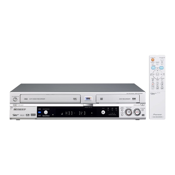
DVD RECORDER
DVR-RT602H-S
THIS MANUAL IS APPLICABLE TO THE FOLLOWING MODEL(S) AND TYPE(S).
Model
Type
DVR-RT602H-S
YXZT5
÷
When servicing this model, some service procedures may reset the customer settings
to the factory default settings. Make sure to explain this to the customer.
An HDD (Hard Disc Drive) is mounted in this product.
The HDD is a precision instrument very vulnerable to shock and electrostatic charges. Please read
"7.5 Cautions on Handling the HDD" in this manual and exercise sufficient caution when handling the
HDD itself, as well as the product with the HDD built in.
When an HDD becomes defective and inoperable, restoration of the user's data recorded on the HDD,
or copying of the user's recorded data to other media (such as a new HDD) is totally impossible.
Before servicing, OBTAIN THE USER'S PRIOR CONSENT to that effect.
The user must be made aware that all recorded data are deleted if the HDD is intialized.
For details, refer to "Important Check Points for Good Servicing" .
PIONEER CORPORATION
PIONEER ELECTRONICS (USA) INC. P.O. Box 1760, Long Beach, CA 90801-1760, U.S.A.
PIONEER EUROPE NV Haven 1087, Keetberglaan 1, 9120 Melsele, Belgium
PIONEER ELECTRONICS ASIACENTRE PTE. LTD. 253 Alexandra Road, #04-01, Singapore 159936
PIONEER CORPORATION 2006
STANDBY/ON
VHS EJECT
VIDEO L (MONO) · AUDIO · R
INPUT2
Power Requirement
AC 220 V to 240 V
4-1, Meguro 1-chome, Meguro-ku, Tokyo 153-8654, Japan
PAL SECAM
OPEN/CLOSE
VHS
DVD
PAUSE LIVE TV
COPY
VHS
VHS/HDD/DVD
SELECT
PLAY
AUTO
HDD
COPY
CH
START
DVD
DVR-RT602H-S
Region No.
2
ORDER NO.
STOP REC
RRV3429
REC
Remarks
T-ZZV JUNE 2006 printed in Japan
Table of Contents

Related Manuals for Pioneer DVR-RT602H-S


Summary of Contents for Pioneer DVR-RT602H-S
-
Page 1: Dvd Recorder
PIONEER CORPORATION 4-1, Meguro 1-chome, Meguro-ku, Tokyo 153-8654, Japan PIONEER ELECTRONICS (USA) INC. P.O. Box 1760, Long Beach, CA 90801-1760, U.S.A. PIONEER EUROPE NV Haven 1087, Keetberglaan 1, 9120 Melsele, Belgium PIONEER ELECTRONICS ASIACENTRE PTE. LTD. 253 Alexandra Road, #04-01, Singapore 159936... -
Page 2: Safety Information
SAFETY INFORMATION LABEL CHECK LASER DIODE CHARACTERISTICS IMPORTANT MAXIMUM OUTPUT POWER: 100 mW THIS PIONEER APPARATUS CONTAINS WAVELENGTH: 654 - 662 nm LASER OF CLASS 1. SERVICING OPERATION OF THE APPARATUS LASER DIODE CHARACTERISTICS SHOULD BE DONE BY A SPECIALLY MAXIMUM OUTPUT POWER: 5 mW INSTRUCTED PERSON. - Page 3 To protect products from damages or failures during transit, the shipping mode should be set or the shipping screws should be installed before shipment. Please be sure to follow this method especially if it is specified in this manual. DVR-RT602H-S...
-
Page 4: Table Of Contents
7.1.2 CPRM ID NUMBER AND DATA SETTING..................108 7.1.3 FIRMWARE DOWNLOADING METHOD..................112 7.1.4 VIDEO ADJUSTMENT FOR SPECIFIC AREA ................115 7.1.5 SERVICE MODE..........................119 7.1.6 EPG SERVICE MODE ........................131 7.1.7 AGING MODE..........................133 7.1.8 HDD CHECK MODE ........................135 DVR-RT602H-S... - Page 5 7.1.11 SETUP SEQUENCE........................143 7.1.12 DISASSEMBLY..........................144 7.2 DISC REMOVAL METHOD ........................152 7.3 TAPE REMOVAL METHOD AT NO POWER SUPPLY ................152 7.4 IC ................................153 7.5 CAUTIONS ON HANDLING THE HDD....................163 7.6 KEY TO ABBREVIATIONS ........................165 7.7 DISC/CONTENT FORMAT ........................166 8. PANEL FACILITIES ............................169 DVR-RT602H-S...
-
Page 6: Specifications
Hyper 300 MHz to 470 MHz 302 MHz to 470 MHz S21 to S41 S21 to S41 B/G - NICAM D/K - NICAM 470 MHz to 862 MHz 470 MHz to 862 MHz E21 to E69 21 to 69 DVR-RT602H-S... -
Page 7: Supplied Accessories
Digital audio ouptut..... . . Coaxial G-LINK™ ......Mini jack DVR-RT602H-S... - Page 8 RETURN CHANNEL • Audio / Video cable(1.5m) ×1 PLAY STOP (red/white/yellow) STOP REC PREV NEXT (06CPBA2006) OPEN DVD RECORDER • G-Link cable ×1 (06CUKC0003) ×1 • RF Antenna cable (06CPL02011) • Dry cell batteries ×2 (AAA/R03) • Operating Instructions DVR-RT602H-S...
- Page 9 DVR-RT602H-S...
-
Page 10: Exploded Views And Parts List
For the applying amount of lubricants or glue, follow the instructions in this manual. (In the case of no amount instructions, apply as you think it appropriate.) 2.1 PACKING 7-15, 25, 26 DVR-RT602H-S... - Page 11 • • • • • • • • > Power Cable 1206158802 Remote Control 07660ML010 Battery Cover VZN1004 Audio/Video Cable 06CPBA2006 RF Antenna Cable 06CPL02011 G-Link Cablle 06CUKC0003 NSP 24 Battery (AAA/03) 141L003010 Information Sheet J2J60229A Information Sheet (HDD:Caution) J2J60249A DVR-RT602H-S...
-
Page 12: Exterior Section
2.2 EXTERIOR SECTION DVR-RT602H-S... - Page 13 SCREW,TAP TITE(B) R PAN 8109130B7U SCREW,TAP TITE(B) R BIND 810923070U SCREW,TAP TITE(B) R BIND 810923053U SCREW,TAP TITE(B) BIND 810923080U SCREW,TAP TITE(B) BIND(3D) 8109K3060U SCREW,TAP TITE(B) WH7 8109I30A0U SCREW,TAP TITE(B)-R BIND 816323075U SCREW,TAP TITE(B) BIND 810723040U SCREW NO.6-32UNC PAN L=5 815316325U SCREW,BIND 810223060U DVR-RT602H-S...
-
Page 14: Front Panel Section
2.3 FRONT PANEL SECTION DVR-RT602H-S... - Page 15 • • • • • • • FLAP,VCR 712WPJC285 FLAP,DVD 712WPJ0963 NSP 8 BADGE,BRAND 7236310032 SPRING,FLAP 743WKA0039 SPRING,FLAP-DVD 743WKA0054 CUSHION 800WR00074 HOLDER,DECK 761WPA0440 DOOR 712WPJ0967 SHEET PC 7230008168 BUTTON,FRAME-DUBBING 738WPBA172 BUTTON,FRAME-EJECT 738WPJA034 SCREW, TAP TITE(P) BIND 8110226A0U SHEET 7230007997 SHEET 7230008029 CUSHION C 800WFAA008 DVR-RT602H-S...
-
Page 16: Deck Assy (Top Section)
(P18 No.19 CD1502) NOTE: Applying positions AA, AB, AC, AD and AE for the grease are displayed for this section. CLASS MARK SERVICE PART NO. Check if the correct grease is applied for each GEM1061 position. GREASE GEM1063 GEM1064 GEM1016 GEM1062 DVR-RT602H-S... - Page 17 Motor, Loading (M101) 1596S98002 Micro Motor (M2003) 1589S11025 > Cylinder Unit Assy (UN4001) A2H301T500 Cord Jumper (CD102) 122F041508 • • • • • • • • • • • • • • • Screw 810722680U Screw 810722640U Screw 810212060U Screw 810912660U DVR-RT602H-S...
-
Page 18: Deck Assy (Bottom Section)
(P16 No.36 CD1502) NOTE: Applying positions AA, AB, AC, AD and AE for the grease are displayed for this section. CLASS MARK SERVICE PART NO. Check if the correct grease is applied for each GEM1061 position. GREASE GEM1063 GEM1064 GEM1016 GEM1062 DVR-RT602H-S... - Page 19 85OP600585 Gear, Joint 85OP600582 Spring, Coupling 85OP800355 Spring, Ring 85OP800356 Holder, Capstan 85OP400554 Cord Jumper (CD1501) 122H071603 Cord Jumper (CD1502) 122Y021902 > Capstan DD Unit (M2001) 1510S98045 Screw, Tap Tite(S) Bind 810722680U E-Ring 83ETW3000U Screw 810912660U Polyslider Washer 82P184505N DVR-RT602H-S...
-
Page 20: Wiring Cable
AC HEAD CD1501 LOADER CP8004 Assy CD1503 CP8002 CP8003 CD1700 SERVICE VCR OPERATION 2 PCB RELAY 1 PCB CP1501 CP1502 SERVICE MAIN CP650 CP1504 CD1504 CP1503 RELAY 2 PCB CP651 HDD UNIT OPERATION 1 PCB DISPLAY PCB CP654 OS651 DVR-RT602H-S... - Page 21 DVR-RT602H-S...
-
Page 22: Block Diagram And Schematic Diagram
3. BLOCK DIAGRAM AND SCHEMATIC DIAGRAM 3.1 BLOCK DIAGRAM 3.1.1 OVERALL BLOCK DIAGRAM DVR-RT602H-S... -
Page 23: Y/C/Audio/Head Amp Block
3.1.2 Y/C/AUDIO/HEAD AMP BLOCK DVR-RT602H-S... -
Page 24: Vcr Micon Block
3.1.3 VCR MICON BLOCK DVR-RT602H-S... -
Page 25: Display Block
3.1.4 DISPLAY BLOCK DVR-RT602H-S... -
Page 26: Hi-Fi Block
3.1.5 Hi-Fi BLOCK DVR-RT602H-S... -
Page 27: Tuner Control Block
3.1.6 TUNER CONTROL BLOCK DVR-RT602H-S... -
Page 28: In/Out Block
3.1.7 IN/OUT BLOCK DVR-RT602H-S... -
Page 29: Av Jack/21Pin Block
3.1.8 AV JACK/21PIN BLOCK DVR-RT602H-S... -
Page 30: Regulator Block
3.1.9 REGULATOR BLOCK DVR-RT602H-S... -
Page 31: Power Block
3.1.10 POWER BLOCK DVR-RT602H-S... -
Page 32: Overall Wiring Diagram
AVL OUT FL DC- FL DC- XAVLTH FL DC+ FL DC+ SC2 BLANK FS YIN VCR MT PCB SC1 FUNC PCB010 POWER PCB V.IN DMF080 FS CIN PCB240 J501_1 DPF012 CONTROL FJ RIN SW+3.3V FJ LIN CH.SW AC230V_50Hz A.IN CD501_1 DVR-RT602H-S... - Page 33 ÷ The > mark found on some component parts indicates the importance of the safety ( 1/3- 3/3) factor of the part. Therefore, when replacing, be sure to use parts of identical designation. AV PCB ASSY ÷ : The power supply is shown with the marked box. (A2J602AD20) DVR-RT602H-S...
-
Page 34: Service Vcr Assy (1/7)
PB SW Q103 Q104 KRA103SRTK CP102_1 R105 R103 KTC3875S_Y_RTK IMSA-9604S-04C CTL- 4.7K CTL- R101 CTL+ CTL+ PB SW C103 R106 Q105 2.2K AUDIO PB 0.0047 B KTC3875S_Y_RTK 4.7K AUDIO REC NORMAL AUDIO REC ST SW Q101 KTC3875S_Y_RTK CD102 2F041508 DVR-RT602H-S... - Page 35 0 5.0 3.2 2.5 2.8 1.1 1.1 1.9 1.8 0.4 0 2.2 2.8 1.9 2.8 1.9 2.8 2.4 2.8 5.0 2.3 2.1 2.8 0 2.1 2.8 NC NC C160 L112 0.1 B P.CON+5V_B 22uH 0305 OSD_V_IN DUMMY_V.SYNC CAUTION: DIGITAL TRANSISTOR CAUTION: DIGITAL TRANSISTOR PCB010 DMF080 DVR-RT602H-S...
-
Page 36: Service Vcr Assy (2/7)
Q3001 C3025 RPI-303 DUMMY_V.SYNC RPI-352C40N RPI-352C40N C.SYNC 6.3V 2.5 2.5 C3082 C3029 0.1 F R3022 CTL+ C3032 C3028 R3023 6.3V CTL- R3123 0 NC C3033 SYSTEM RESET IC SCL_V IC3001 C3030 820PCH SDA_V PST3231NR 0.0015 B D3002 RESET 1SS133 DVR-RT602H-S... - Page 37 MP_DATA_IN BUFFER R3037 D3003 H8 WRITE JG3005 Q3018 MP_DATA_OUT KTC3875S_Y_RTK H8 WRITE JG3006 1SS133 330K H8 WRITE JG3007 RESET R3035 R3039 RESET C3083 H8 WRITE JG3008 H8 WRITE JG3009 AT+5V(M-CON) H8 WRITE JG3010 C3086 MP_CLK 0.0022 B PCB010 DMF080 DVR-RT602H-S...
-
Page 38: Service Vcr Assy(3/7)
3.9K FJ_LIN FRONT_A_L FJ_LIN W832 NORMAL_A_IN FJ_RIN FJ_RIN FRONT_A_R R8007 1K LED_DVD LED_DVD L701 R80091K P.CON+9V LED_HDD 1/4W LED_HDD R80051K R714 22uH 0305 1/4W SWL_VCR LED_EXT LED_EXT 1/4W 27K 1/4W LED_SATA V+5V V+5V KEY1 KEY1 W822 CP8002 00_6232_015_006_800+ IC_GND DVR-RT602H-S... - Page 39 HIFI_ENV.DET L-CH FJ_RIN KANP IN SEL C738 HIFI_L HIFI_R 0.01 B VREF A GND SWL_VCR SWR_VCR REC_MUTE-H FJ_VIN C712 FS_YIN FS_CIN C746 FROM/TO REGULATOR P.CON+5V_A -22V P.CON+9V SW3.3V AT+5.2V HEATER_DC+ HEATER_DC- PCB010 DMF080 CAUTION: DIGITAL TRANSISTOR CAUTION: DIGITAL TRANSISTOR DVR-RT602H-S...
-
Page 40: Service Vcr Assy(4/7)
FROM/TO VCR MICON ACDET REEL_GND WAKE_UP P_SAVE X3302 XRESET 15MHz ACDET X3301 32.768KHz FROM/TO HIFI LED_EXT LED_DUB C3305 RESET_SW KEY1 Q3302 0.1 B KRC103SRTK KEY2 W837 KEY3 FLCLK FLSTB RESET IC FLDATA IC3301 V+5V BD4846G-TR SDET2 W836 SEL_IR IC_GND DVR-RT602H-S... - Page 41 0.1 B XRST1 SC2_FUNC STATCHG 6.8K SDA_T C3327 SCL_T 4706.3V C3330 6.3V FROM/TO REGULATOR R3338 C3337 FLON 6.3V TUON FANCTRL R3334 V+5V P_CONT W830 RFTHRU AT+12V AT+5.2V L3302 S801X S801Y 10uH PCB010 DMF080 CAUTION: DIGITAL TRANSISTOR (C3005 GND) (CP8002 GND) DVR-RT602H-S...
-
Page 42: Service Vcr Assy(5/7)
P+9XP P+9XP FJ_VIN FJ VIN FROM/TO REGULATOR AT+5.2V AT5+5.2V TU_V TU VIN AT+12V AT+12V TU_A-R TU RIN C8160 SW3.3V AT+5.2V 100P TU_A-L TU LIN REG_SW C8159 Q8104 AT+12V Q8116 KRC103SRTK KRC103SRTK 100P CH CAUTION: DIGITAL TRANSISTOR CAUTION: DIGITAL TRANSISTOR DVR-RT602H-S... - Page 43 RJ LOUT C8120_1 C8118 RJ VOUT 6.3V 1000 C8123 YUV Y 6.3V 1000 C8116 YUV U 6.3V C8121 YUV V R8135 XRST1 6.3V XREST1 R8137 B-IR B-IR XP_SAVE TXDGL TXDGL R8138 RCA-332-00-02 RXDGL RXDGL S-VIDEO OUT J8101 DIN-409A J8103 DVR-RT602H-S...
-
Page 44: Service Vcr Assy(6/7)
IC801 NICAM/A2 IIS_DA_IN1 MSP3417G-QG-B8 P.CON+5V_B C804 SC1_IN_L IIS_DA_OUT 0.1 B SC1_IN_R 13 SDA IIS_WS 44 AVSS C802 12 SCL VREFTOP IIS_CL R801 SDA_T MONO IN 4701/4W R802 SCL_T 4701/4W L802 C811 22uH0305 47PCH R817 Q803 X801 2SC2814-(4/5)B-E 18.432MHz W829 DVR-RT602H-S... - Page 45 TU301 TMQZ2-440A L302 BU+5V 22uH SCL_T SDA_T C306 C305 33PCH R303 R301 C303 100 1/4W Q301 BUFFER R302 33PCH KTA1504S_Y_RTK 100 1/4W L301 TU+5V 22uH 30.4 +32V V.OUT TU_V BUFFER R318 Q302 KTA1504S_Y_RTK DVR-RT602H-S...
-
Page 46: Service Vcr Assy(7/7)
TV_SW Q1708 KRA104SRTK P_CONT 34.8 TU SW TU SW UNREG+38V Q1725 Q1706 TU SW Q1709 KRC103SRTK KRC103SRTK KRC103SRTK -28V FL DC - FL DC + CP531 NOTE:THE DC VOLTAGE EACH PART WAS MEASURED WITH THE DIGITAL TESTER DURING PLAYBACK. DVR-RT602H-S... - Page 47 -19.4 1/4W R1730 HEATER_DC+ 471/2W Q1717 -19.3 471/2W KTA1281_Y FL SW Q1720 R1732 KTC3875S_Y_RTK FIP_SW Q1719 KTA1504S_Y_RTK CAUTION: DIGITAL TRANSISTOR -25.2 CAUTION: DIGITAL TRANSISTOR -25.5 R1722 -26.3 DRIVER -25.6 Q1721 -25.6 KTC3209_Y HEATER SW Q1718 KTC3875S_Y_RTK PCB010 C1726 DMF080 DVR-RT602H-S...
-
Page 48: Av Pcb Assy (1/3)
SAMUTE RS_Y RS Y RS_C RS C SC1_ROUT RJ ROUT SC1_LOUT RJ LOUT RJ_VOUT RJ VOUT YUV_Y YUV Y YUV_U YUV U YUV_V YUV V XREST1 XRESET1 B-IR B-IR TXDGL TXDGL RXDGL RXDGL CD8302 2H0U1101 CP8102 CAUTION: DIGITAL TRANSISTOR DVR-RT602H-S... - Page 49 0.1 B RS_C AT+5.2V AT+12V C8302 P+5XP 22 23 24 25 26 27 28 29 30 SWIC_C 0 2.5 2.7 5.0 2.5 2.5 5.0 2.7 C8303 RGB_CIN IC8304 MM1507XNRE VIDEO SW IC C8321 CP8103 PCBD20 DEE062 CAUTION: DIGITAL TRANSISTOR DVR-RT602H-S...
-
Page 50: Av Pcb Assy (2/3)
10K +-1% YTRAP BFPOUT C8432 R8441 R8431 NT/PAL 680 +-1% 6.3V Q8410 KTC3875S_Y_RTK VCC2 SCIN VOUT C8404 IC8405 TC7SU04FU 0.1 B BOUT GOUT C843627P CH RGB_CIN Q8403 KTA1504S_Y_RTK ROUT R8407 1.6K R8442 C8437 IC8403 BH7236AF 2.2K 27P CH W809 DVR-RT602H-S... - Page 51 R8489 SC1_BOUT 6.3V SC1_FUNC SC1_N-LINK C8466 R8490 SC1_GOUT 6.3V R8495150 C8469 R8492 SC1_R/COUT R8485150 SC1_RGBOUT 6.3V C8443 6.3V C8467 6.3V R8488 SC1_V/YOUT SC1_V/YIN D8412 D8415 D8418 D8409 DF3A5.6FU DF3A5.6FU DF3A5.6FU DF3A5.6FU CAUTION: DIGITAL TRANSISTOR CAUTION: DIGITAL TRANSISTOR PCBD20 DEE062 DVR-RT602H-S...
-
Page 52: Av Pcb Assy (3/3)
3.12 AV PCB ASSY (3/3) AV PCB ASSSY (A2J602AD20) •IR BLASTER BLOCK DVR-RT602H-S... - Page 53 DVR-RT602H-S...
-
Page 54: Service Main Assy(1/3)
1112 GNDD TP607 10 2 CLOSE R604 LPS1 TP606 V+12M LD_M BLACK TP605 LD_P V+5M CN601 GNDD V+5M TP518 TP517 HU_P TP516 HU_M TP515 HV_P TP514 HV_M TP513 HW_P TP512 HW_M TP511 TP510 TP509 TP508 TP507 GNDD CN501 GNDD DVR-RT602H-S... - Page 55 GNDS GNDD V+3D V+3D R281 47 3 CN401 GNDM NC(SW0) TP5757 TP5759 D6(AG) TP5761 D1(SL) TP5762 D0(MA) GN D TP250 XRESET XREST TP251 TX_FE TX_FE TP252 RX_FE RX_FE TP253 R280 V+3D 22 0 TP254 C532 47 3 GNDD GNDM DVR-RT602H-S...
-
Page 56: Service Main Assy(2/3)
(GNDS) GNDD V+3V V_ENC GNDD GNDD (GNDS) C230 L1008 GNDD V+3FE R1003 GND D GNDD R1004 GNDD GND D R1005 V_LV3 R1001 DTL1106-A R1006 V_WP3 1R5V GNDD 1R5V PVDD L1010 L1007 BTH1103-A R1007 GNDD R1008 V_WP1 DTL1106-A GNDD GNDD DVR-RT602H-S... - Page 57 TBA0 TADRS11 TBA1 TADRS9 R1285 TADRS10 TADRS8 DBA0 TBA0 TBA0 A10/AP TADRS0 TADRS7 DBA1 TBA1 TBA1 TADRS1 TADRS6 R1286 TADRS2 TADRS5 R1287 TADRS3 TADRS4 C1230 C1228 VDD3 VSS1 DRAS TRAS DCAS TCAS GNDD R1288 DCLKO TCLKO TCLKO DCLKNO R1289 DVR-RT602H-S...
-
Page 58: Service Main Assy(3/3)
ADPOW VCOM GNDD 10 4 V+3D AD_BC K AGND SCLK ADCCLKO IC3103 R3105 R3103 TC74VHC157FT MCLK AD_LRCK DV_XADC LRCK SELECT AD_ADATA DGND SDTO 18 20 GNDD R3110 AK5359ET (AK5358ET) GNDD GNDD R3111 UMF21N-TLB R3112 47 0 GNDD GNDD GNDD DVR-RT602H-S... - Page 59 R3732 56 2 XRST 1 RB501V D3711 JTRST RB501V D3712 232RST V+3D GNDD TC7WH34F U R3703 HSTtoM R3501 GNDD Q3501 HST_TO_M 2SC4081(QR)-TLB 47 1 R3704 SSTtoM R3505 DAT_TO_M 75R0 (F ) GNDD IC3701 C3703 SPDIFO R3706 GNDD GNDD GNDD DVR-RT602H-S...
-
Page 60: Display Pcb, Operation 1 And 2 Pcb Assys
SW653 : CH-/DOWN SW662 : HELP 5.6K 3.3K 2.2K 2.2K SW654 : DUBDING SW663 : <>/RIGHT SW666 : STOP SW667 : REC CAUTION: DIGITAL TRANSISTOR DVR-RT602H-S... - Page 61 R689 100PCH C654 LTL-1CHAE-002A 0.1 B ORANGE LED_SW LED_DUB Q654 C655 KRC103SRTK 0.1 B D657 R675 R680 LTL-1CHEE-002A R690 R691 D656 LTL-1CHEE-002A LED_REC LED_SW Q656 KRC103SRTK PCBDP0 D655 R692 R693 DEF090 LTL-1CHEE-002A D650 R694 R695 LTL-1CHEE-002A LED_SW Q650 KRC103SRTK DVR-RT602H-S...
-
Page 62: Relay 1 And 2 Pcb Assys
13 14 ATDMACK ATDATA14 11 12 DD14 ATINTRQ RESERVED ATDATA1 ATADR1 PDIAG ATDATA13 DD13 ATADR0 ATADR2 ATDATA2 ATCS0 ATCS1 ATDATA12 DD12 ACTIVE ATDATA3 ATDATA11 DD11 ATDATA4 ATDATA10 DD10 ATDATA5 ATDATA9 ATDATA6 ATDATA8 ATDATA7 ATRESET HRESET# CD1501 PCBDB0 BH040121 DEF102 DVR-RT602H-S... - Page 63 IMSA-9639S-24Y905 C_OUT C_OUT Y_OUT Y_OUT VENC_RST VENC_RST C1507 C1508 V+3D AMCLKI AMCLKI ALRCK ALRCK ARCK ARCK DV_INT1 DV_INT1 DV_INT2 DV_INT2 DV_RST DV_RST DV_TX DV_TX DV_RX DV_RX V+5D V+5D V+3D V+3D V+3D V+5D V+3D V+3D V+3D CD1503 2H0O2002 PCBDC0 DEF103 DVR-RT602H-S...
-
Page 64: Power Pcb Assy
137.2 16.6 D507 R524 D511 1SS133 1.2K 1/2W 1H3-E D508 C508 FR155-F D512 470PCH 1H3-E 18.9 HS503 R519 R513 763WAAA116 D504 R516 220 1/4W 1SS133 C510 MTZJ6.2B-EIC 0.1 B R511 C535 0.1 B IC501 KIA431A-AT VOLTAGE CTL OUT GND DVR-RT602H-S... - Page 65 +-1% +-1% 763WAA0309 V+5V C525 MGND 0.1 B SW+1.53V SW+1.53V C540 0.1 B AT+5.3V L504 AT+5.3V 22uH TSL0808 EV+5.8V EV+5.8V C517 D514 0.1 B CD530 WIRE MGND WML6016038 Q504 KTA1504S_Y_RTK SAFTY SW R523 Q503 KTC3875S_Y_RTK SAFTY SW PCB240 DPF012 DVR-RT602H-S...
-
Page 66: Wave Forms
SERVICE VCR ASSY Y/C/AUDIO 10 s 500 s 10.0V 500mV 1.0V VCR MICON 10 s 200 s 20ns 100mV 500mV 1.0V 20 ns 500ms 50mV 500 mV 1.0V 500 s 50ns 500ms 500mV 100mV 1.0V Hi-Fi 20ms 10ms 1.0V 500mV 200mV DVR-RT602H-S... - Page 67 10 s 500 s 500mV 200mV 1.0V 10ms 10 s 10 s 500mV 1.0V 500mV TUNER MICON 10 s 10 s 10 s 500mV 500mV 200mV 20ns 10 s 200mV 500mV 200mV IN/OUT 500 s 200ns 1.0V 200mV 200mV DVR-RT602H-S...
- Page 68 AV SWITCH 20ns 10 s 500 s 500mV 100mV 500mV 21PIN 10 s 500 s 10 s 500mV 500mV 500mV 21PIN 10 s 10 s 500mV 200mV 10 s 10 s 500mV 200mV 10 s 10 s 200mV 500mV DVR-RT602H-S...
- Page 69 V: 1V/div. H: 20us/div. V: 1V/div. H: 100ns/div. V: 1V/div. H: 20us/div. IC3101 Pin10 (AD_LRCK) CN2301 Pin19 (C_OUT) IC501 Pin23 (XDMUTE2) X201 (16.93MHz) V: 0.5V/div. H: 10us/div. V: 1V/div. H: 20us/div. V: 1V/div. H: 20ns/div. V: 1V/div. H: 5us/div. DVR-RT602H-S...
- Page 70 V: 2V/div. H: 200us/div. CN2301 Pin2 (RCH IN) CN2301 Pin23 (RCH OUT) V: 1V/div. H: 200us/div. V: 2V/div. H: 200us/div. IC3201 Pin16 (DACCLKO) V: 1V/div. H: 20ns/div. IC3201 Pin1 (DACBCKO) V: 1V/div. H: 100ns/div. IC3201 Pin3 (DACLRCKO) V: 0.5V/div. H: 5us/div. DVR-RT602H-S...
-
Page 71: Pcb Connection Diagram
Symbol In PCB Symbol In Schematic Part Name Diagrams Diagrams C E B Capacitor Connector Transistor B C E SIDE A Transistor with resistor B C E Field effect SIDE B P.C.Board Chip Part transistor Resistor array 3-terminal regulator DVR-RT602H-S... -
Page 72: Service Vcr Assy
D3003 R3104 W335 R3105 C730 SW3001 W206 W333 W334 W203 W330 W332 W006 Q8105 W331 Q8111 W205 W803 C3014 W841 W022 L702 W329 W225 W842 W048 W214 W326 D3012 W325 W213 X3001 W164 W204 W163 R3017 W034 CP103 DMF080A DVR-RT602H-S... - Page 73 D8102 W122 W121 W132 CP8302 D8103 R709 Q8105 W128 Q8111 W131 L801 W130 W059 W157 W264 W263 W100 L804 L805 R302 W359 R303 L802 W358 R814 W160 TU301 R808 W357 W159 X801 L301 CP103 W356 W158 DMF080A W355 W046 DVR-RT602H-S...
- Page 74 Q101 Q104 Q3310 Q3304 Q8103 IC3099 IC3099 Q3005 Q105 Q8119 Q3305 Q8118 Q103 Q8101 Q8102 Q3307 IC4601 Q8014 IC101 Q8013 IC102 IC8101 Q3018 Q8023 IC3005 Q3306 Q3311 Q3309 Q3308 IC701 Q8104 IC3002 Q801 Q802 Q803 IC801 Q301 IC3001 Q302 DVR-RT602H-S...
- Page 75 SIDE A CP8104 CP1701 CP1703 DVR-RT602H-S...
-
Page 76: Av Pcb, Relay 1 And 2 Pcb Assys
IC8401 Q8418 Q8402 Q8402 R8407 Q8403 Q8403 R8410 C8412 IC8403 C8411 Q8404 Q8404 L8401 R8485 R8495 DEF101A C8330 CP8301 SIDE B Q8303 IC8405 IC8302 Q8401 Q8423 IC8406 Q8421 Q8424 Q8425 Q8420 Q8406 Q8413 Q8409 Q8408 Q8407 Q8412 Q8411 Q8410 DVR-RT602H-S... - Page 77 SIDE A RELAY1 RELAY2 PCB ASSY PCB ASSY CP1502 CP8004 IC8404 W814 J8401 D8401 R8479 Q8415 Q8417 Q8419 Q8418 W811 R8451 DEF103A CN3802 J8402 R8485 D8409 R8495 D8412 CN3801 CP8301 CP8302 CP8301 CP8302 CP8102 CP8103 SIDE B CP8301 CP8302 CP1502 DVR-RT602H-S...
-
Page 78: Service Main Assy
D3101 R3807 R3821 R3805 R3854 D3104 R2309 R3813 R3811 R2313 C3215 C3105 R3824 R3817 R3853 R3820 R3808 R230 R2307 C3816 R3810 R3812 R2304 R3809 R3823 R3816 D3103 D3102 R3822 R230 CN3802 R3863 R3861 CN2301 CN3801 CN3801 CN2301 CP1501 CP8104 DVR-RT602H-S... - Page 79 R1301 R1304 R1275 R1267 R1302 D3101 R1276 D3104 R1260 R1303 R4539 C1215 C1235 R1222 C1303 R1220 R2302 C4547 C4546 R1218 R2305 R1213 u-guide2 D3103 D3102 R2301 R2603 C1216 C4545 R4528 R4529 C4544 R3504 CN2601 C1212 C1201 L1201 IC4510 (VNP2038-A) DVR-RT602H-S...
- Page 80 C1211 R5606 Q4561 IC3701 R2213 R2209 IC1221 C1227 IC1301 C2208 C1209 C1214 R2208 R2212 TP203 TP68 TP69 Q2206 R1272 R1217 R4537 R1216 Q3501 Q3501 IC2202 TP2603 TP2604 TP614 TP2602 R3501 TP91 TP90 C1228 TP2605 TP2311 TP2601 TP2606 R3001 TP89 DVR-RT602H-S...
- Page 81 TP5744 TP83 TP81 TP87 R3815 TP91 TP90 TP99 2605 TP2312 TP5726 TP5739 TP5743 TP5734 TP5720 R2306 C2221 TP2304 TP2303 C2223 TP2311 TP2606 R3001 TP2305 TP2309 TP2302 TP5721 TP5728 TP5736 TP5740 TP5764 TP89 TP2306 TP5724 TP5731 TP5738 TP5742 TP5746 (VNP2038-B) DVR-RT602H-S...
-
Page 82: Display, Operation 1 And 2 Pcb Assys
• Parts mounted View C663 C658 W008 V651 OS651 DEF090A SW662 CP654 C656_1 CP652 SW651 CP654 CP652 CP8003 DEF096A OPERATION PCB ASSY SIDE A • Chip Parts mounted View Q654 IC651 Q650 Q657 Q656 CP652 CP654 Q653 Q652 Q651 DVR-RT602H-S... - Page 83 D650 SW665 D660 D659 SW667 SW663 SW660 D658 D656 SW657 D654 D657 SW664 DEF097A SW651 D653 R649 R648 J650 D652 DEF096A CP651 D651 PERATION1 J653 J652 J651 CB ASSY CP650 CP654 OPERATION2 PCB ASSY CP8002 SIDE A CP651 CP654 DVR-RT602H-S...
-
Page 84: Power Pcb Assy
C506 IC503 IC503 D508 C512 D511 T501 R530 D509 B501 C513 D507 W008 W007 IC504 IC504 W012 C503 C516 RISK OF FIRE - REPLACE HS503 D502 AS MARKED. F501_1 R505 R503 FH501_1 FH502_1 L509 L501 AC IN J501_1 DPF012A DVR-RT602H-S... - Page 85 SIDE A SIDE A POWER PCB ASSY • Chip Parts mounted View CP531 CP530 Q504 Q503 AC IN DVR-RT602H-S...
-
Page 86: Pcb Parts List
IC8405 IC TC7SU04FU I55F0U04FU IC8406 IC TC7W53FU I55F07W53U Q3007 PHOTO COUPLER RPI-303 0002700690 Q3018 TRANSISTOR,SILICON KTC3875S TCAA3875SY Q101 TRANSISTOR,SILICON KTC3875S TCAA3875SY Q3301 COMPOUND TRANSISTOR KRC111SRTK TNAAJ05003 Q102 TRANSISTOR,SILICON KTC3203 TCAT032034 Q3302 COMPOUND TRANSISTOR KRC103SRTK TNAAC05002 Q103 COMPOUND TRANSISTOR KRA103SRTK TPAAC05002 DVR-RT602H-S... - Page 87 D8414 DIODE, ZENER DF3A5.6FU DE5RD5R610 Q8425 TRANSISTOR,SILICON KTC3875S TCAA3875SY D8415 DIODE, ZENER DF3A5.6FU DE5RD5R610 D101 DIODE,SILICON 1SS133T-77 D1VT001330 D8416 DIODE, ZENER DF3A5.6FU DE5RD5R610 D650 LED, LTL-1CHEE-002A 0021E2Q140 D8417 DIODE, ZENER DF3A5.6FU DE5RD5R610 D651 LED, LTL-1CHAE-002A 0021E3Q030 D8418 DIODE, ZENER DF3A5.6FU DE5RD5R610 DVR-RT602H-S...
- Page 88 L8105 COIL 47 UH 021LA6470J CP8004 CONNECTOR PCB SIDE 069JV40200 L8301 COIL 100 UH 02167F101J CP8101 CONNECTOR PCB SIDE 069V140339 CP8102 CONNECTOR PCB SIDE 069J1C0078 L8302 COIL 22 UH 0216S8220K CP8103 CONNECTOR PCB SIDE 069J1B0078 L8303 COIL 100 UH 02167F101J DVR-RT602H-S...
- Page 89 L1001, L1003, L1004, L1006-L1008 DTL1106 C3204 CKSSYB331K50 L1201, L3102, EMI FILTER DTL1106 C114 CKSSYB332K50 L1811 LCYA150J2520 C116 CKSSYB333K10 L1801 LCYA390J2520 C232, C233 CKSSYB471K50 C148, C220, C223 CKSSYB472K25 CAPACITORS C1081 CCSSCH100D50 C147, C1804, C1814, C532 CKSSYB473K10 C158-C162, C1813 CCSSCH101J50 C297, C3208, C3210 CKSSYB681K50 DVR-RT602H-S...
- Page 90 R1301 RS1/16S4700F R1052 RS1/16S6200F R3505 RS1/16S75R0F R1054 RS1/16S9100F R181 RS1/16SS4701F R510, R511 RS1/4SA2R0J R115, R1003-R1008, R1314, R2506 RS1/16S###J R3837, R3850 RS1/16S###J Other Resistors RS1/16SS###J OTHERS CN502 4P CONNECTOR DKN1288 CN501 D-SOCKET(14P) DKN1312 CN601 5P CONNECTOR DKN1402 CN101 CONNECTOR DKN1404 DVR-RT602H-S...
-
Page 91: Adjustment
Romcorrection data check sum. PLAY/REC 0010 PLAY/REC total hours. = (16 × 16 × 16 × thousands digit value) + (16 × 16 × hundreds digit value) Fig. 1 + (16 × tens digit value) + (ones digit value) DVR-RT602H-S... - Page 92 Clean the full erase head in the same manner. (Refer to the figure below.) NOTE Do not exert force against the cylinder head. Do not move the chamois upward or downward on the head. Use the chamois one by one. Cylinder Head Audio Control Head DVR-RT602H-S...
-
Page 93: Adjustment Items And Necessary Adjustment Points
6.6.1 PG SHIFTER 6.8.1 LD POWER ADJUSTMENT Replacing Mechanical point None SERVICE VCR ASSY Electrical point 6.6.1 PG SHIFTER Replacing Mechanical point None IC3099 (VCR SIDE EEPROM) Electrical point 6.6.1 PG SHIFTER 6.7.1 VCR SIDE EEPROM (IC3099) INITIAL SETTING DVR-RT602H-S... -
Page 94: Servicing Fixtures And Tools
Parts Name Remarks GGV1559 Jig for LD Power Adjutment for LD Power Adjustment GGV1477 FFC Cable (10P) for LD Power Adjustment GGV1054 CD-ROM Test Disc for LD Power Adjustment GGF1036 DVD Dual Layer Test Disc for LD Power Adjustment DVR-RT602H-S... -
Page 95: Service Mode List
(The BOT, EOT, and the Reel Sensor do not work and the VCR deck can be operated without a cassette tape.) 2. In case of using a cassette tape, press the EJECT button to insert or eject a cassette tape. Turn on the power and re-check the cable before checking the trouble points. DVR-RT602H-S... -
Page 96: Mechanical Adjustments
2. Confirm that the right meter of the torque tape indicates 50~90gf•cm during playback in SP mode. Height Adjustment Washer 2.6 × 4.7 × T0.13 3. Confirm that the left meter of the torque tape indicates 2.6 × 4.7 × T0.25 25~40gf•cm during playback in SP mode. Fig. 1-1-B DVR-RT602H-S... - Page 97 Cassette Holder Assy Fig. 1-4-A Torque Gauge/Adpter CH-1 (GGF1508/GGF1506) Envelope (TP101) CH-1 CH-2 Torque Gauge/Adpter Track Track CH-2 (GGF1507/GGF1506) SW Pulse (TP3002) Fig. 2-1-A Entrance Exit S Reel T Reel A : B 3 : 2 Fig. 2-1-B Fig. 1-4-B DVR-RT602H-S...
- Page 98 7. If the difference are more than 3 steps, set the X Value adjustment driver (GGF1510) to 4 of Fig. 2-2-B. Change the X Value and adjust it so that the value becomes within 2 steps. 0.25 ± 0.05 mm Fig. 2-2-C DVR-RT602H-S...
- Page 99 1. Tension Connect 6. P4 Post 2. Tension Arm 7. T Brake Spring 3. Guide Roller 8. T Reel 4. Audio/Control Head 9. S Reel 5. X value adjustment driver hole 10. Adjusting section for the Tension Arm position DVR-RT602H-S...
-
Page 100: Electrical Adjustments
PAUSE LIVE TV button on the set for more than 2 seconds and start the auto-adjustment. 6. Confirm that the head switching pulse wave form is like Fig.1-1-A/Fig.1-1-B. CH-2 6.5 H CH-1 Fig. 1-1-A CH-2 CH-1 6.5 H Fig. 1-1-B DVR-RT602H-S... - Page 101 AC HEAD CD1501 LOADER CP8004 Assy CD1503 CP8002 CP8003 CD1700 SERVICE VCR OPERATION 2 PCB RELAY 1 PCB CP1501 CP1502 SERVICE MAIN CP650 CP1504 CD1504 CP1503 RELAY 2 PCB CP651 HDD UNIT OPERATION 1 PCB DISPLAY PCB CP654 OS651 DVR-RT602H-S...
-
Page 102: When Replacing Eeprom (Memory) Ic
8. Repeat steps 4 to 7 until all data has been checked. 9. When satisfied correct DATA has been entered, turn POWER off (return to STANDBY MODE) to finish DATA input. 10. Unplug the AC cord, then plug it in. DVR-RT602H-S... -
Page 103: Ld Power Adjustment
Connect the 10-pin flexible cable Special tool for to the lower part of CN401. adjusting the LD power • Setting of the switches on the special tool for adjusting the LD power GGF1559 Set all five switches to ON. DVR-RT602H-S... - Page 104 13. Set the power sources for the HDD and the flexible connecting cable for ATA (40-pin) to their original statuses. [ Points to be confirmed ] 1. Make sure that real-time recording on a DVD-R/-RW/RAM will finish normally. 2. Play back a recorded disc and make sure that playback is performed without a problem. DVR-RT602H-S...
-
Page 105: General Information
HDD contents 1. Model setting SERVICE MAIN ASSY 2. LD power adjustment 3. CPRM setting 4. Firmware update SERVICE VCR 1. Model setting ASSY 2. Firmware update 1. LD power adjustment SERVICE LOADER ASSY 1. CPRM setting 2. Firmware update DVR-RT602H-S... - Page 106 PLAY HDD/DVD Load the DL Disc(*1) Recording stop(*2) , then press Play (*2) to tray Open/Close(*2) Firmware Download *1 DL Disc : Download Disc 1 Holding user setting V data *2 Key on the front panel 2 Shipping mode DVR-RT602H-S...
-
Page 107: Model Setting
C : ∗ ∗ ∗ ∗ ∗ ∗ ∗ ∗ ∗ REGION VHS_VER : 0163AC19A CHECK_SUM :∗ ∗ ∗ ∗ ∗ ∗ ∗ ∗ ∗ Press [ESC] then [DISP] keys by using the remote control unit for servicing, and then confirm each Model Name (for example " DVR-RT602H/YXTL5 "). DVR-RT602H-S... -
Page 108: Cprm Id Number And Data Setting
"How to confirm the ID number" shown below. • Input the ID number while the unit is in Stop mode. • After the data are read from the data disc (Type 2), the disc will automatically be unloaded. DVR-RT602H-S... - Page 109 Before servicing, OBTAIN THE USER'S PRIOR CONSENT to that effect. Execute HOME MENU → Disc Setup → Intialize HDD → Initialize → Start *Goes to normal operation with no caution Disc Setup Basic Initialize Start Initialize Finalize Initialize HDD After OSD displaying "Finished" after initilaization, reboot. DVR-RT602H-S...
-
Page 110
CLOSE key "7/0" on the player. After confirming this message, press CLEAR key to exit the input mode. [Recorder's ID Data Setting] [Recorder's ID Data Setting]
Exit Rom Write OK ! Insert The ID Data Disc ! Exit DVR-RT602H-S... -
Page 111
ID Number ? [ 0 0 0 0 0 0 0 0 1] Compare > 0 0 0 0 0 0 0 0 1 OK ?
Enter Memory Clear ID Data Setting Mode Input ID Number ! DVR-RT602H-S... -
Page 112: Firmware Downloading Method
O A D - 5 W N L O A D - 2 * After download is completed, the power turns off, and turns on and a disc tray closes automatically. * It takes for about 7-8 minutes until download is completed. DVR-RT602H-S... - Page 113 If the program cannot be downloaded from the disc, replace the IR Blaster microcomputer (IC801 : TUJB ASSY). The setting way to shipping mode (Reference) At 2 lines of the [Procedures], press a "VHS EJECT" button while pressing a "START" button. DVR-RT602H-S...
- Page 114 • Other factors can be considerd if download fails 3 times or more. • And it takes about 20 minutes for updating the firmware. * TUNERCON and IR con program is not downloaded by this way, so do disc-download for TUNERCON and IR con. DVR-RT602H-S...
-
Page 115: Video Adjustment For Specific Area
• The setting indicated with an asterisk (*) is the default. • The channels to be indicated for "Input Channel" are as shown below: Line inputs: L1,L2 Tuner channels: Channels received by the tuner (channels to be set in Specific-Channel Setting mode, etc.) DVR-RT602H-S... - Page 116 • The currently selected input mode (TUNER or LINE) is displayed for "Input." • If L1 or L2 is selected for input, general settings for the line input can be made, and if TUNER is selected, general settings for the tuner input can be made. DVR-RT602H-S...
- Page 117 DVR-RT602H-S...
- Page 118 DVR-RT602H-S...
-
Page 119: Service Mode
While the GUI screen is not displayed, press the ESC then DISP keys. How to enter and change subscreens of the first screen: While the first screen is displayed, press the DIG/ANA key repeatedly until your desired subscreen is displayed. The subscreens change [How to quit] Press the ESC key. DVR-RT602H-S... - Page 120 7 IR Braster u-com information 8 DEVICE information (EMMA type, ES No.) 9 FLASH ROM information 0 Region No. - CPRM information (CPRM key No.) = Version No. of the VHS microcomputer ~ Check_SUM information of VHS initial setting DVR-RT602H-S...
- Page 121 C : ∗ ∗ ∗ ∗ ∗ ∗ ∗ ∗ ∗ REGION CHECK_SUM : ∗ ∗ ∗ ∗ ∗ ∗ ∗ ∗ VHS_VER : 0163AC19A : ∗∗ ch Input channel Input CH : ∗∗∗∗ mV AGC Volt AGC voltage Subscreen 1 DVR-RT602H-S...
- Page 122 During VR mode playback, the average value of the past 10 VOBUs is displayed. During DVD-Video or Video mode playback, the average value of the past 256 sectors is displayed. During VR mode playback, the speed ratio of the drive (/: normal, no indication: double speed) is also displayed. DVR-RT602H-S...
- Page 123 (to display the CPRM setting screen, press the ESC then the STEREO keys). Notes: • The data on cumulative HDD-on time are not cleared when resetting to factory-preset values is performed. • The data on cumulative HDD-on time are not cleared when the system-control computer software is downloaded. DVR-RT602H-S...
- Page 124 [ x 3 Fwd ], [SPEED-] : The setting value decreases by 1. The setting value is reset to default. [CLEAR] – To exit the OSD Filter Setting and [ESC] – – clear the screen (Appears the tuner screen.) DVR-RT602H-S...
- Page 125 MAIN Assy is replaced, the data will be cleared. However, after the LOADER Assy is replaced, data on lighting time of each LD will be retained in the MAIN Assy. Therefore, before either the MAIN Assy or LOADER Assy is to be replaced, it is recommended that you write down the lighting time data. DVR-RT602H-S...
- Page 126 4-digit hexadecimal) Writer adjustment data for straight (non-HDD) model No condition (FFFF is diplayed when the writer is not adjusted.) If the results of degradation of the LDs for CDs and DVDs are both NG, replace the drive. DVR-RT602H-S...
- Page 127 • The two error-log screens can be switched by pressing the SPEED+ or SPEED- key. • For details on error messages, see Table 1 "Description of VR-recording-related errors". (4) Subscreen 5 to 11 (These subscreens are not for service use.) DVR-RT602H-S...
- Page 128 VC HDD C Err VC HDD Inf NG No information on Video Mode Copy HDD VC HDD Info NG Format failed Video Mode Copy idling NG VC Idling NG Analizing Video Mode Copy Pack failed VC Pck Anl NG DVR-RT602H-S...
- Page 129 Abnormal temperatute PARAM NO ACCP Recording parameter is not matched. Process Over Process is overfull. Protect Src * Source to be recorded is copy-protected. Rec Pause * No operation permitted during recording pause Relocation Do VR-recording data was relocated DVR-RT602H-S...
- Page 130 UDF = Universal Disc Format RMA = Recording Management Area PCA = Power Calibration Area MKB = Media Key Block OPC = Optical Power Control TMP_VMGI = Temporary Video Manager Information NWA = Next Writable Address Border = from Lead-in to Lead-out DVR-RT602H-S...
-
Page 131: Epg Service Mode
A number 999,999 or greater is displayed as "999999." [Tips] In a case where only "HS" is displayed in the MD column of the logs, the host channel has not been found. It is necessary to check the country and postal-code settings in the user settings. DVR-RT602H-S... - Page 132 : Slice level control Auto-Tu Con, Manual - Syscon. : Equalizer setting (ON, OFF) : Slice level (10~30 hex) (Only when the slice Cont is Manual.) Note: The data on lines 12-14 are for software development, not for service use. DVR-RT602H-S...
-
Page 133: Aging Mode
OSD. Note: Recording time depends on the recording rate set. For example, if the recording rate is MN32, only up to 60 titles can be registered. Check the setting for recording rate before performing aging. DVR-RT602H-S... - Page 134 During Aging, the number of loops is indicated on the FL display, as shown below. [Tips] [AGING 0001] If an error is generated, the aging operation stops. Note: Indications on the FL display are retained, and this information is also retained as an OSD. DVR-RT602H-S...
-
Page 135: Hdd Check Mode
Execute Extended Self-Test. Result of the diagnosis: Failure in HDD Measures to be taken: Replacement of HDD Has an error occurred? Execute writing test, if required. Execute HDD Read/Write Check. Has an error occurred? Result of the diagnosis: No abnormality DVR-RT602H-S... - Page 136 The status of the unit recommended during diagnosis is as follows: All stop, no timer recording (including auto-recording), and Input selection to L1, L2. DVR-RT602H-S...
- Page 137 The HDD has come to the end or near the end of its service life. not exceeded: The HDD has not reached the end of its service life. To return to the menu screen, press the "Clear" key. DVR-RT602H-S...
- Page 138 If it is from 3 to 7, the HDD must be replaced. Note: If the result of the second test is the same, replacement of the HDD is required. Example: No error Example: With an error To return to the menu screen, press the "Clear" key. DVR-RT602H-S...
- Page 139 If it is from 3 to 7, the HDD must be replaced. Note: If the result of the second test is the same, replacement of the HDD is required. Example: No error Example: With an error To return to the menu screen, press the "Clear" key. DVR-RT602H-S...
- Page 140 • If no error occurs in any of the Write/Read/Compare items, the HDD is in normal condition and is not required to be replaced. A block other than the HDD is in failure. • If any error occurs, the HDD must be replaced. To terminate the diagnostic program, press the "ESC" key. DVR-RT602H-S...
-
Page 141: Diagnosis Of The Main Assy
(Poor contact with the Pickup Assy.) video and audio? 2 Failure in the periphery of IC101 (Failure in the periphery of the RF IC.) Failure in the periphery of IC101 (There is possibility of failure of the EMMA2RFE chip.) DVR-RT602H-S... -
Page 142: Note On Replacement Of The Sdram
Replacement of only the defective SDRAM (IC1201 or IC1221) is possible. Possible malfunctions If SDRAMs made by different manufacturers are mounted on the MAIN Assy, the following malfunctions may occur: 1 The power does not come on. 2 High-speed dubbing disabled 3 Other malfunctions related to the SDRAM DVR-RT602H-S... -
Page 143: Setup Sequence
FL display ∗1: If both the drive ID check and starting/ID check of HDD failed, "CPRM ERR" is first Is disc in? displayed on FL display. Is disc valid? Repair required? Tray Open Playback Repair process requested? Playback Stop DVR-RT602H-S... -
Page 144: Disassembly
8. Remove the HDD Angle (R) and RELAY 2 PCB in the direction of arrow (C). 9. Remove the RELAY 1 PCB in the direction of arrow (C). RELAY 1 PCB HDD Angle (L) Flap Fig. 1-2 HDD Angle (R) RELAY 2 PCB Fig. 1-4 DVR-RT602H-S... - Page 145 3. Remove the 3 screws 2 . 4. Disconnect the following connectors: (CP101, CP102, CP103, CP3001) 5. Remove the AC Head Cover and VCR Deck in the direction of arrow. AC Head Cover VCR Deck op Holder Fig. 1-6 DVR-RT602H-S...
- Page 146 2. Push the Locker R to remove the Cassette Side R. 3. Remove the Cassette Side L. Locker R Main Chassis Cassette Side R Flap Lever Link Lever Main Chassis Link Unit Cassette Side L Fig. 2-2 Fig. 2-4 DVR-RT602H-S...
- Page 147 Loading Motor Tension Band Tension Connect Fig. 2-6-C Tension Connect Cassette Opener [OK] Tension Band Tension Connect [NG] Fig. 2-5-C Tension Band Fig. 2-6-D Pink Capstan DD Unit Loading Motor Tension Connect White Main Chassis Fig. 2-5-D Fig. 2-6-D DVR-RT602H-S...
- Page 148 5. When you install the reel, clean the shaft and grease it (FG-84M). (If you do not grease, noise may be heard in FF/REW mode.) 6. After installing the reel, adjust the height of the reel. (Refer to MECHANICAL ADJUSTMENT) DVR-RT602H-S...
- Page 149 3. When you install the A/C Head, tighten the screw (1) first, then tighten the screw (2), finally tighten the screw (3). Cylinder Unit Assy A/C Head A/C Head Spring A/C Head Base Screw Torque: Screw Torque: 3 ± 0.5kgf•cm 5 ± 0.5kgf•cm (Screw 1) Fig. 2-10-A Fig. 2-12 DVR-RT602H-S...
- Page 150 1. In case of the Pinch Roller Cam and Main Cam installation, install them as the circled section of Fig. 2-15-B so that the each markers are met. Loading Arm T Unit Loading Arm S Unit (Refer to Fig. 2-14B) Fig. 2-15-B DVR-RT602H-S...
- Page 151 [NG] 1. Remove the P4 Cap. 2. Unlock the support 1 and remove the Cassette Guide Cassette Guide Post Post. 3. Remove the Inclined Base S/T Unit. 4. Remove the screw 2. 5. Remove the LED Reflector. Fig. 2-17-C DVR-RT602H-S...
-
Page 152: Disc Removal Method
5. Repeat the above step 3~4. Then take out the Video Cassette from the Deck Chassis. Be careful not to scratch on the tape. Loading Motor Screw Capstan DD Unit Pinch Roller Cam Main Cam Clutch Assy Insert hole for screwdriver Main Chassis (Front Side) Fig. 1 Fig. 2 DVR-RT602H-S... - Page 153 Input selection of video selector INSEL 2 of LA73031 Input selection of video selector INSEL 3 of LA73031 SELV3 YCSEL CVBS or Y/C selection of video selector STBYVS Standby mode switch of video selector − VSS4 − VDD4 VDD4 DVR-RT602H-S...
- Page 154 DC/OC converter for +32V generation Transmission for RS232-C terminal P32/UTX1 TXD1 Reception for RS232-C terminal P33/URX1 RXD1 P34/UTX2 TXD2 UART2 transmission Not used UART2 transmission Not used P35/URX2 RXD2 SYS → Tuner HS_TTOM System controller communication handshake − VDDODA VDDODA DVR-RT602H-S...
- Page 155 P_SAVEBS Not used for Europe model Tuner → Sys Communication data line of sys con PA0/SO7 SD_TTOM Sys → Tuner Communication data line of sys con PA1/SI7/SB7 SD_MTOT Sys → Tuner Communication clock of sys con 100 PA2/SCK7 SCK_MTOT DVR-RT602H-S...
- Page 156 SERVICE L: Service mode H: Usually P00/AN0 I Reserved. (L output) AVcc AVCC - Power supply for A/D Conversion. Detection terminal for Power Fail. P10/_IRQ0 POWER_FAIL H: Normal, L: Power Fail P11/_IRQ1 Reserved. (L output) P12/_IRQ2 Reserved. (L output) DVR-RT602H-S...
- Page 157 O Terminal IIC BUS for MPEGu-con. (CLK) P25/SDA0 MPEG_IIC_DATA I/O Terminal IIC BUS for MPEGu-con. (DATA) P24/SCL1 IIC_CLK O Communication terminal for IC/EEPROM. (IIC BUS Clock) P23/SDA1 IIC_DATA I/O Communication terminal for IC/EEPROM. (IIC BUS Data) P22/SCK1 O Reserved. O Reserved. P21/SO1 O Reserved. P20/SI1 DVR-RT602H-S...
- Page 158 BOT is usually invalid for tape IN detection in the low power consumption mode. P72/PPG2 BOT2 The state is observed in the low power consumption mode in the state of tape EJECT, and P.ON and tape IN works by the H-->L detection. DVR-RT602H-S...
- Page 159 H: sink chip and Z: insertion and L at a black level: It is not. Vpulse DUMMY.V.SYNC When the microcomputer resetting, and blacking out, it is. "L" at the POWER OFF. - GND. Csync C.SYNC I Composite SYNC input terminal. For servoC.SYNC from Y/C is input. - Power supply terminal. DVR-RT602H-S...
- Page 160 UPD61272F1-107KA3A (SERVICE MAIN ASSY : IC1001) (EMMA2RFE) • DVDR IC BLOCK DIAGRAM DVR-RT602H-S...
- Page 161 PIN FUNCTION Pin No. Name Function Serial clock line Serial data line Address input 0 Address input 1 Address input 2 I/O0 I/O0 (open drain) I/O1 I/O1 Supply ground 9±14 I/O2±I/O7 I/O2 to I/O7 Active-LOW reset input RESET Supply voltage DVR-RT602H-S...
- Page 162 107F072360(BH7236AF) (AV PCB ASSY : IC8403) • Color TV Signal Encoder BLOCK DIAGRAM PIN FUNCTION DVR-RT602H-S...
-
Page 163: Cautions On Handling The Hdd
• When packing, use the antistatic bag and packing materials in which the repair part for service was delivered. Attach a copy of the slip for service or a memo stating symptoms in as much detail as possible. DVR-RT602H-S... - Page 164 Outline and part No. of the HDDs *Pioneer's part No. is not stamped. Western Digital Model Pioneer's Capacity Manufacture's Name Part No. Part No. (for service) WD800BB DVR-RT602H-S 80GB VXF1066 -xxHJKC • When replacing the HDD, carefully check the capacity and manufacturer's part No. on the part label to avoid replacing with a similar but inappropriate product.
-
Page 165: Key To Abbreviations
: Inverter : Visual Search Rewind : Voltage Super Source : Killer V-SYNC : Vertical-Synchronization : Voltage Tuning : Left : Light Emitting Diode X'TAL : Crystal LIMIT AMP : Limiter Amplifier LM, LDM : Loading Motor : Luminance/Chrominance DVR-RT602H-S... -
Page 166: Disc/Content Format
It is possible that when loading or ejecting a should be compatible with 2 x or 4 x DualDisc, the opposite side to that being played will be scratched. Scratched discs recording; DVD+R with 2.4 x to 8 x may not be playable. recording. DVR-RT602H-S... - Page 167 1 DRM (digital rights management) copy protection is a technology designed to prevent unauthorized copying by restricting playback, etc. of compressed audio files on devices other the PC (or other recording equipment) used to record it. For detailed information, please see the instruction manuals or help files that came with your PC (or other WMA recording equipment) and/or software. DVR-RT602H-S...
- Page 168 In these particular instances, check with the software publisher for more detailed information. Discs recorded in packet write mode (UDF format) are not compatible with this recorder. Check the DVD-R/RW or CD-R/RW software disc boxes for additional compatibility information. DVR-RT602H-S...
-
Page 169: Panel Facilities
AUDIO INPUT2 13 INPUT2 VIDEO / AUDIO Standard video and stereo analog audio inputs, especially suitable for camcorders, game consoles, portable audio, etc. 14 S-VIDEO input A high-quality S-Video input, especially suitable for camcorders, game consoles, portable audio, etc. DVR-RT602H-S... -
Page 170: Rear Panel Section
TV or monitor with an S-Video input. your TV. CONTROL IN Use to control this recorder from the remote sensor of another Pioneer component with a CONTROL OUT terminal and bearing the Pioneer mark. Connect the CONTROL OUT of the other component to the CONTROL IN of this recorder using a mini- plug cord. - Page 171 Play List mode. VPS / PDC Lights when receiving a VPS/PDC Shows the remote control mode (if broadcast during a VPS/PDC-enabled nothing is displayed, the remote control timer recording. mode is 1). Lights when an unfinalized Video mode disc is loaded. DVR-RT602H-S...
- Page 172 SHIFT and press to set a timer DISC NAVIGATOR / TOP MENU recording from the GUIDE Plus+™ Press to display the Disc Navigator screen, system. or the top menu if a DVD-Video or finalized DVD-R/-RW (Video) disc is loaded. DVR-RT602H-S...
- Page 173 When in the GUIDE Plus+™ system, use to VHS for recording and playback. jump directly to the Menu bar. 12 INFO 22 DISPLAY Press to see additional information for the Displays/changes the on-screen highlighted item in GUIDE Plus+™. information displays. DVR-RT602H-S...
- Page 174 Before shipping out the product, be sure to clean the following positions by using the prescribed cleaning tools: Position to be cleaned Cleaning tools Pickup lenses Cleaning liquid : GEM1004 Cleaning paper : GED-008 Position to be cleaned Cleaning tools Fans Cleaning paper : GED-008 DVR-RT602H-S...