
Related Manuals for Siemens DESIGO PXM20


Summary of Contents for Siemens DESIGO PXM20
- Page 1 DESIGO PX PXM20 / PXM20-E operator unit User's guide Version 2.2 and later CM110754en_02 Building Technologies 17 Dec 2009...
-
Page 2: Table Of Contents
3.2.16 Domain ID (PXM20 only)..........25 3.2.17 Network scope............. 25 Login and log-out ............26 Connecting to the network .......... 26 Login................27 Logout ................. 28 2/70 Siemens PXM20 / PXM20-E operator unit CM110754en_02 Building Technologies Contents 17 Dec 2009... - Page 3 List view............... 57 Service support ............58 11.1 (Wiring test) ..............58 11.2 The Wink command ............ 61 11.3 Debug information ............62 Index ..................63 3/70 Siemens PXM20 / PXM20-E operator unit CM110754en_02 Building Technologies Contents 17 Dec 2009...
-
Page 4: Revision History
The following trade names and product names are registered trademarks: BACnet American National Standard (ANSI/ASHRAE 135- 1995) ® Echelon Corporation, San Jose, USA ORKS LonTalk® 4/70 Siemens PXM20 / PXM20-E operator unit CM110754en_02 Building Technologies Revision history 17 Dec 2009... -
Page 5: About This Manual
Important For this reason, the descriptions in this manual are intended as examples, designed to clarify the basic operating principles of the PXM20 operator unit. 5/70 Siemens PXM20 / PXM20-E operator unit CM110754en_02 Building Technologies About this manual 17 Dec 2009... -
Page 6: Printing Conventions
Important Particular attention should be paid to text marked with this symbol. Note A note qualifies an immediately preceding statement or statements. 6/70 Siemens PXM20 / PXM20-E operator unit CM110754en_02 Building Technologies About this manual... -
Page 7: Display And Control Elements
When the view restriction option is On, the red Alarm LED lights up in the event of an alarm even if you are not logged in. Exception The LED does not flash in response to an event. 7/70 Siemens PXM20 / PXM20-E operator unit CM110754en_02 Building Technologies Display and control elements... -
Page 8: Audible Signal
Page Down are used to indicate that there is too much text to display at once. Scroll up and down with these keys to display the whole text. 8/70 Siemens PXM20 / PXM20-E operator unit CM110754en_02 Building Technologies Display and control elements... - Page 9 (e.g. the editing of a value), change over to the dialog box of the next higher level or close a pop-up window. . Holding down ESC for more than 2 seconds ("Long ESC") closes all the active pop-up windows. 9/70 Siemens PXM20 / PXM20-E operator unit CM110754en_02 Building Technologies Display and control elements...
- Page 10 Figure 2-2 Figure 2-3 Example: "Setpoint for cooling" Pressing the key again displays a dialog box with general information about the associated window. 10/70 Siemens PXM20 / PXM20-E operator unit CM110754en_02 Building Technologies Display and control elements 17 Dec 2009...
-
Page 11: Display
The example above shows page 1 of 2 of the dialog box for the Air handling unit. 11/70 Siemens PXM20 / PXM20-E operator unit CM110754en_02 Building Technologies Display and control elements... -
Page 12: Operator Field
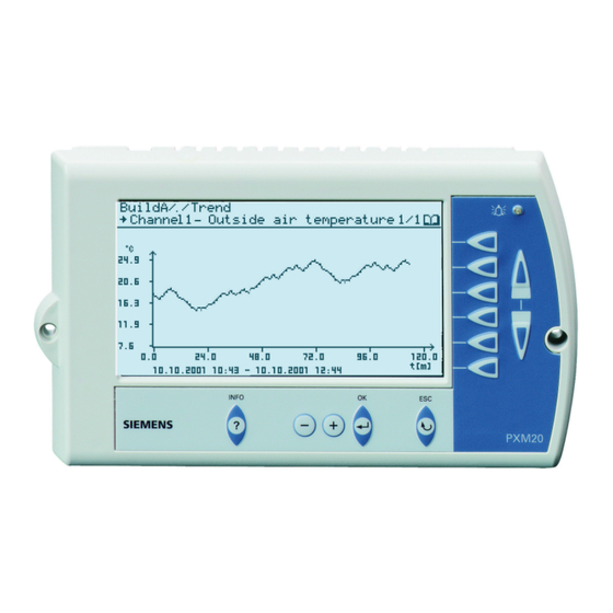
An arrowhead symbol, for values which you can edit. Graphics Trends and heating curves are displayed in graph form. Figure 2-5 Trends graph 12/70 Siemens PXM20 / PXM20-E operator unit CM110754en_02 Building Technologies Display and control elements 17 Dec 2009... - Page 13 Dialog boxes containing the relevant information are also displayed when you press the key. Figure 2-7 Dialog box with confirmation prompt 13/70 Siemens PXM20 / PXM20-E operator unit CM110754en_02 Building Technologies Display and control elements...
-
Page 14: Symbols
Operating parameters Value object Interface variable Calendar / Calendar entry Trend Time schedules Set date and time User-defined system settings Alarming & functions 14/70 Siemens PXM20 / PXM20-E operator unit CM110754en_02 Building Technologies Display and control elements 17 Dec 2009... - Page 15 Add new users Delete user Change password Device (Primary Server) Device (Backup Server) Wiring test (service engineers only) Wink Debug information (service engineers only) 15/70 Siemens PXM20 / PXM20-E operator unit CM110754en_02 Building Technologies Display and control elements 17 Dec 2009...
- Page 16 Reset alarm or event in Alarm & event history Symbols Description Status Work in progress Override (manually overwritten value) Life safety Plant security Fault Override active Out of service Delay Switch 16/70 Siemens PXM20 / PXM20-E operator unit CM110754en_02 Building Technologies Display and control elements 17 Dec 2009...
-
Page 17: Settings
Open Alarming & functions for the current site. This is where you will find all the entries which you use to modify settings in the system using your PXM20 operator unit. Figure 3-2 Alarming & functions 17/70 Siemens PXM20 / PXM20-E operator unit CM110754en_02 Building Technologies Settings... -
Page 18: System
The basic settings are the last Sunday in March at 0200 hours for the start of summer time and the last Sunday in October at 0300 hours for the end of summer time. 18/70 Siemens PXM20 / PXM20-E operator unit CM110754en_02 Building Technologies... -
Page 19: Pxm20 Operator Unit
2. Select the required entry; the value will start flashing. 3. Configure the value as required. 4. Always save the new settings and restart the PXM20 operator unit. 19/70 Siemens PXM20 / PXM20-E operator unit CM110754en_02 Building Technologies Settings 17 Dec 2009... -
Page 20: Language
BACnet communications between the different IP segments (separated by IP routers). The PXM20-E from another IP segment can register itself with BBMD as a foreign device. This 20/70 Siemens PXM20 / PXM20-E operator unit CM110754en_02 Building Technologies Settings... -
Page 21: View Restriction
Select the devices you want to be able see for your work, and set them to Visible (Figure 3-9). Note It is recommended that the Primary Device also be set to Visible. 21/70 Siemens PXM20 / PXM20-E operator unit CM110754en_02 Building Technologies Settings... -
Page 22: Date And Time Format
3.2.4 Date and time format Select either the American or the European date and time format. 3.2.5 Contrast The display contrast can be set here: 22/70 Siemens PXM20 / PXM20-E operator unit CM110754en_02 Building Technologies Settings 17 Dec 2009... -
Page 23: Display Long Texts
Display saver on This option lets you define the time period (from 5 to 60 minutes in 5- minute increments) after which the display saver is to switch on. 23/70 Siemens PXM20 / PXM20-E operator unit CM110754en_02 Building Technologies Settings... -
Page 24: Main Value
Only a subset of the standard properties, as in the BACnet standard, is displayed. In the context of PXM20 and PXM20-E, the term "third-party" or "devices from third-party manufacturers" is used to refer to "non-PX devices". 24/70 Siemens PXM20 / PXM20-E operator unit CM110754en_02 Building Technologies Settings 17 Dec 2009... -
Page 25: Domain Id (Pxm20 Only)
BACnet devices connected to the same network, or also with BACnet devices connected to another BACnet network. Important This setting should be modified only by fully trained staff. 25/70 Siemens PXM20 / PXM20-E operator unit CM110754en_02 Building Technologies Settings 17 Dec 2009... -
Page 26: Login And Log-Out
The login procedure is in two steps: 1. Select a site If no sites are listed, this means that no automation station in the network has been defined as the primary server. 26/70 Siemens PXM20 / PXM20-E operator unit CM110754en_02 Building Technologies Login and log-out... -
Page 27: Login
Logging in to Before you can log in to a new site, you must first log out from the another site current site (see the next section). 27/70 Siemens PXM20 / PXM20-E operator unit CM110754en_02 Building Technologies Login and log-out... -
Page 28: Logout
1. Within the site, go to Alarming & functions. Logout 2. Select Logout. 3. Confirm that you really do want to log out. 4. The site overview appears again (Figure 3-1). 28/70 Siemens PXM20 / PXM20-E operator unit CM110754en_02 Building Technologies Login and log-out 17 Dec 2009... -
Page 29: Navigation
If there are several pages in one display, use the Page Up and Page Down keys to change to the next or previous page. The total number to page of pages is shown in the top right corner of the display: 29/70 Siemens PXM20 / PXM20-E operator unit CM110754en_02 Building Technologies Navigation... -
Page 30: Reading And Editing Values
To keep the manual as clear as possible, the instruction "Press the direct access key" is not repeated. Example: "Select the month and the year". 30/70 Siemens PXM20 / PXM20-E operator unit CM110754en_02 Building Technologies Reading and editing values... -
Page 31: Example: Setting A Setpoint
Example: Setting a setpoint Navigate to the value that you want to edit. Set the required value. Figure 6-2 Setting a manual setpoint 31/70 Siemens PXM20 / PXM20-E operator unit CM110754en_02 Building Technologies Reading and editing values 17 Dec 2009... -
Page 32: Example: Editing The Heating Curve
Select LIST VIEW for access to a list of all parameters, inputs and curve outputs. Figure 6-4 Heating curve: list view, page 1 32/70 Siemens PXM20 / PXM20-E operator unit CM110754en_02 Building Technologies Reading and editing values 17 Dec 2009... -
Page 33: Forced Control
You can use the direct access key to cancel the forced control in the dialog box again. The forced control symbol is displayed after the input or output has Forced control been forced. symbol 33/70 Siemens PXM20 / PXM20-E operator unit CM110754en_02 Building Technologies Reading and editing values 17 Dec 2009... -
Page 34: Alarms
The display shows a time stamp, the object name, the notification text and the alarm priority. In the case of alarm messages, you can display the Alarm viewer directly (see Section 7.2.1). 34/70 Siemens PXM20 / PXM20-E operator unit CM110754en_02 Building Technologies... -
Page 35: Alarm Acknowledgement
You can go to the Alarm viewer either from the Alarming & functions window, or display it directly from the alarm pop-up. Figure 7-2 Alarm viewer 35/70 Siemens PXM20 / PXM20-E operator unit CM110754en_02 Building Technologies Alarms 17 Dec 2009... -
Page 36: Selecting An Event Or Alarm
6. You can now select either ACKNOWLEDGE or DETAILS. The procedure for events is basically the same as for alarms. Unlike alarms, however, you do not need to acknowledge events. 36/70 Siemens PXM20 / PXM20-E operator unit CM110754en_02 Building Technologies... -
Page 37: Alarm Acknowledgement / Alarm & Event Details
OBJECT PROPERTIES lets you navigate directly to the alarm source. Press ESC to return to the Alarm viewer. Your user access rights will determine whether or not you have Note access to Object properties. 37/70 Siemens PXM20 / PXM20-E operator unit CM110754en_02 Building Technologies Alarms 17 Dec 2009... -
Page 38: Alarm & Event History
The following information is displayed for a maximum of 30 entries: All the most recently received alarms The most recent alarm acknowledgements The most recent events 38/70 Siemens PXM20 / PXM20-E operator unit CM110754en_02 Building Technologies Alarms... - Page 39 As with Alarm viewer, you can invoke an individual alarm or event here, and view the details. Symbols in the Alarm & event history Unacknowledged alarm Normal state, existing alarm unacknowledged System event Acknowledged Reset 39/70 Siemens PXM20 / PXM20-E operator unit CM110754en_02 Building Technologies Alarms 17 Dec 2009...
-
Page 40: Access Rights
Members of a group are authorized to add new users to groups at a lower hierarchical level. Within the current site, go to Alarming & functions and select User definition 2 Select Add new user 40/70 Siemens PXM20 / PXM20-E operator unit CM110754en_02 Building Technologies Access rights 17 Dec 2009... - Page 41 Select initials for the user you have defined 9 Answer the prompt to save the new user entry: SAVE USER The display will revert to the User definition dialog box 41/70 Siemens PXM20 / PXM20-E operator unit CM110754en_02 Building Technologies Access rights...
-
Page 42: Remove User
Select the user, for which you want to edit the data. Make the required changes and confirm them by selecting SAVE USER. 42/70 Siemens PXM20 / PXM20-E operator unit CM110754en_02 Building Technologies Access rights... -
Page 43: Setting Time Schedules
A graphics-based display of the selected day appears on the second line. You can select the individual switching points with the associated direct access key. The next line displays the values for the selected switching point. 43/70 Siemens PXM20 / PXM20-E operator unit CM110754en_02 Building Technologies Setting time schedules... -
Page 44: Editing The Switching Points
To add an entry select NEW ENTRY and edit the new entry. 9.1.1.4 Delete entry To delete an entry, first select the entry to be deleted, and then select DELETE ENTRY. 44/70 Siemens PXM20 / PXM20-E operator unit CM110754en_02 Building Technologies Setting time schedules 17 Dec 2009... -
Page 45: Exception Schedule
Select the required day and confirm with OK. A list of all the exceptions for the selected day is displayed. You can edit this display directly. 45/70 Siemens PXM20 / PXM20-E operator unit CM110754en_02 Building Technologies Setting time schedules... -
Page 46: Listing All The Exceptions
Schedule exception list (Figure 9-3). The next section describes how to adapt this exception to your own particular needs. 46/70 Siemens PXM20 / PXM20-E operator unit CM110754en_02 Building Technologies Setting time schedules... -
Page 47: Editing A Local Exception
Select EDIT PROFILE for access to the 24-hour profile of an exception. In this dialog box, you can select whether you want to modify the program or to delete all entries. 47/70 Siemens PXM20 / PXM20-E operator unit CM110754en_02 Building Technologies... - Page 48 All entries will be deleted from the system. This button is used to delete the selected exception. Use this button to revert to the Schedule exception list, Figure 9-3). 48/70 Siemens PXM20 / PXM20-E operator unit CM110754en_02 Building Technologies Setting time schedules...
-
Page 49: Edit Calendar Object
When editing calendar entries, extreme caution is advised, as this STOP can sometimes affect the exception programs of other time schedules. 49/70 Siemens PXM20 / PXM20-E operator unit CM110754en_02 Building Technologies Setting time schedules 17 Dec 2009... -
Page 50: Trend Function And Settings
(Figure 10-3). Section 10.3 describes how to set the trend parameters and define the type of view required.<0} The data point is automatically assigned to the first free channel. 50/70 Siemens PXM20 / PXM20-E operator unit CM110754en_02 Building Technologies Trend function and settings... -
Page 51: Displaying An Existing Trend
The next section describes how to set the trend parameters and define the type of view required. This button allows you to stop all trend logging and delete all configured trend charts. 51/70 Siemens PXM20 / PXM20-E operator unit CM110754en_02 Building Technologies Trend function and settings... -
Page 52: Main Trend Dialog Box
From the main trend dialog box (Figure 10-3) select Trend configuration . You can now modify the parameters for the required trend logging. Figure 10-4 Configuration, pages 1 and 2 52/70 Siemens PXM20 / PXM20-E operator unit CM110754en_02 Building Technologies Trend function and settings... - Page 53 (start time, stop time and referenced data point). You can display the trend data in three different views, as described in the next section. 53/70 Siemens PXM20 / PXM20-E operator unit CM110754en_02 Building Technologies Trend function and settings...
-
Page 54: Graphic View
Use Compare with channel to compare the selected trend with another trend you have set up (see Figure 10-9). Select GRAPHIC to confirm your settings and display the trend. 54/70 Siemens PXM20 / PXM20-E operator unit CM110754en_02 Building Technologies Trend function and settings... - Page 55 Figure 10-7 Graphic view with two channels Setting guides A guide line can be set and moved by use of the <+> and <-> keys. The data display is also refreshed. 55/70 Siemens PXM20 / PXM20-E operator unit CM110754en_02 Building Technologies Trend function and settings...
-
Page 56: Graphic View Online
The trend is displayed soon as you confirm your entries via GRAPHIC. You can reset the graphic display by pressing OK. Figure 10-9 Online trend 56/70 Siemens PXM20 / PXM20-E operator unit CM110754en_02 Building Technologies Trend function and settings 17 Dec 2009... -
Page 57: List View
List view Instead of displaying the logged values in graph form, you can view them in list form. Figure 10-10 Trend values in the list view 57/70 Siemens PXM20 / PXM20-E operator unit CM110754en_02 Building Technologies Trend function and settings... -
Page 58: Service Support
Go to Alarming & functions and choose Wiring test. – Follow the instructions in the display, and press the service pin of the required automation station. 58/70 Siemens PXM20 / PXM20-E operator unit CM110754en_02 Building Technologies Service support 17 Dec 2009... - Page 59 RUN STA ERR TX SERVICE TX SERVICE Servicepin for IP devices Figure 11-3 Position of the service pin in a PX modular automation station The wiring test is carried out. 59/70 Siemens PXM20 / PXM20-E operator unit CM110754en_02 Building Technologies Service support 17 Dec 2009...
- Page 60 The use of this IP address is not checked. If the wiring test is carried out on a different PXM20-E operator unit, a master reset of the automation is required before you start. 60/70 Siemens PXM20 / PXM20-E operator unit CM110754en_02 Building Technologies...
-
Page 61: The Wink Command
The identification process is carried out with the Wink command. Figure 11-5 The “Wink” command To send the Wink command, select Send service pin message. This immediately triggers the Wink signal. Figure 11-6 61/70 Siemens PXM20 / PXM20-E operator unit CM110754en_02 Building Technologies Service support 17 Dec 2009... -
Page 62: Debug Information
The time at which the error occurred. The format is as follows: occurrence Day, month, minute, second and millisecond since 01.01.1970 00:00. Example: 11801 DAYS 09:25:06.000 62/70 Siemens PXM20 / PXM20-E operator unit CM110754en_02 Building Technologies Service support 17 Dec 2009... -
Page 63: Index
Alarm pop-up ................23, 34 Alarm text mode................23 Alarm viewer ..................35 Alarming & functions..............17, 28 Audible signal ................8, 23, 34 Buzzer....................23 Cancel audible signal...............35 CHANGE DATE................47 CHANGE PROGRAM..............44 63/70 Siemens PXM20 / PXM20-E operator unit CM110754en_02 Index 17 Dec 2009 Building Technologies... - Page 64 Delete ..................44 New ....................44 ESC key..................6, 9 Event DETAILS..................37 Events....................34 Select..................36 Exception list Edit Calendar object ..............49 EXCEPTION OVERVIEW..............45 Exception program EXCEPTION OVERVIEW ............45 Exception schedule................45 64/70 Siemens PXM20 / PXM20-E operator unit CM110754en_02 Index 17 Dec 2009 Building Technologies...
- Page 65 LED....................7, 34 LIST VIEW Heating curve ................32 List view, online trend ..............57 LOG DATA POINT................50 Log in and log out ................26 Login ....................27 START ..................26 Logout....................28 65/70 Siemens PXM20 / PXM20-E operator unit CM110754en_02 Index 17 Dec 2009 Building Technologies...
- Page 66 Schedule exception list ..............45 CHANGE DATE................47 DELETE ENTRY ................48 EDIT PROFILE ................47 NEW LOCAL EXCEPTION............46 SAVE & EXIT................48 Schedule exception list: ..............49 Scheduler..................43 Service pin .................58, 59 66/70 Siemens PXM20 / PXM20-E operator unit CM110754en_02 Index 17 Dec 2009 Building Technologies...
- Page 67 Favorites ..................14 Forced control................33 Global objects................15 Hierarchical element..............14 Information..................14 Input....................14 Interface variable ................14 Log-out ..................14 Navigate ..................14 Output ..................14 Override ..................16 Parameters .................14 Power control................14 Reset ..................39 67/70 Siemens PXM20 / PXM20-E operator unit CM110754en_02 Index 17 Dec 2009 Building Technologies...
- Page 68 RELEASE ALL CHANNELS ............51 RELEASE CHANNEL..............52 SAVE TREND SETTINGS............53 Set up new trend ................50 Start time ..................53 Stop time ..................53 Stop when full ................53 Views ..................50 Trend configuration................52 68/70 Siemens PXM20 / PXM20-E operator unit CM110754en_02 Index 17 Dec 2009 Building Technologies...
- Page 69 Force ..................33 Reading and writing..............30 View Graphic ..................32 List view..................32 Welcome window................24 Wildcards ..................27 Wiring test..................58 List of inputs and outputs............60 WIRING TEST .................27 Write access ..................40 69/70 Siemens PXM20 / PXM20-E operator unit CM110754en_02 Index 17 Dec 2009 Building Technologies...
- Page 70 Industry Sector Building Technologies Division International Headquarters Gubelstrasse 22 CH-6301 Zug Tel. +41 41-724 24 24 Fax +41 41-724 35 22 © 2003 - 2009 Siemens Switzerland Ltd www.buildingtechnologies.siemens.com Subject to change 70/70 Siemens PXM20 / PXM20-E operator unit CM110754en_02...