Table of Contents
Table of Contents

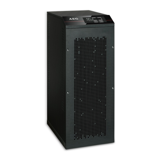
Related Manuals for AEG UPS 10 kVA


Summary of Contents for AEG UPS 10 kVA
- Page 1 UPS USER MANUAL AEG HE UPS 10 kVA UPS 15 kVA UPS 20 kVA...
- Page 2 OMD94016 REV. C...
- Page 3 OMD94016 REV. WARNING This is a Class A-UPS Product. In a domestic environment, this product may cause radio interference, in which case, the user may be take additional measures.
-
Page 4: Table Of Contents
OMD94016 REV. C 1. Scope ................7 2. Safety rules and warnings ........8 3. General ups description ..........9 TYPOLOGY ............... 9 SYSTEM DESCRIPTION ........10 3.2.1 Rectifier ............... 10 3.2.2 Inverter ..............10 3.2.3 Battery and battery charger ......... 11 3.2.4 Static bypass ............ - Page 5 OMD94016 REV. 6. Settings and advanced operations ......29 SETTING DATE AND TIME ........30 DISPLAY LANGUAGE SETTING ......31 NEW BATTERY INSTALLATION ......31 BATTERY CONFIGURATION ......... 31 SETTING THE MODBUS PARAMETERS ....33 UPS TEST ............... 33 BATTERY TEST ............34 SYSTEM RESET .............
- Page 6 OMD94016 REV. C INDEX OF FIGURES Figure 1: Block diagram ................. 9 Figure 2: Normal operation ..............12 Figure 3: Load supplied by bypass ............13 Figure 4: Battery operation ..............14 Figure 5: Manual bypass ..............15 Figure 6: UPS front panel ..............18 Figure 7: UPS mimic panel ..............
-
Page 7: Scope
OMD94016 REV. 1. SCOPE The instructions contained in this section of the manual apply to the UPS systems indicated below. AEG HE 10 kVA • AEG HE 15 kVA • AEG HE 20 kVA • STORING DOCUMENTATION This manual and any other supporting technical documentation relating to the product must be stored and made accessible to personnel in the immediate vicinity of the UPS. -
Page 8: Safety Rules And Warnings
OMD94016 REV. C 2. SAFETY RULES AND WARNINGS INJURY HAZARD DUE TO ELECTRIC SHOCK! Always respect all the safety instructions and, in particular: any work on the unit must be carried out by qualified personnel; • internal components can only be accessed after disconnecting the •... -
Page 9: General Ups Description
OMD94016 REV. 3. GENERAL UPS DESCRIPTION The UPS systems of the AEG HE line use IGBT technology with a high changeover frequency in order to allow a low distortion of the current re- injected into the supply line, as well as high quality and stability of the output voltage. -
Page 10: System Description
OMD94016 REV. C SYSTEM DESCRIPTION 3.2.1 RECTIFIER It converts the three-phase voltage of the AC mains into continuous DC voltage. It uses a three-phase fully-controlled IGBT bridge with a low harmonic absorption. The control electronics use a 32 bit µP of latest generation that allows reduction of the distortion of the current absorbed by mains (THDi) to less than 5 %. -
Page 11: Battery And Battery Charger
OMD94016 REV. 3.2.3 BATTERY AND BATTERY CHARGER The battery can be installed inside or outside the UPS. The battery charger logic is completely integrated in the rectifier’s control electronics. The battery is charged, according to the DIN 41773 Standard, every time it has been partially or completely discharged. -
Page 12: Operating Status
OMD94016 REV. C OPERATING STATUS The UPS has four different operating modes, as described below: Normal operation • Bypass operation • Battery operation • Manual bypass • 3.3.1 NORMAL OPERATION During normal operation all of the circuit breakers/isolators are closed, except for MBCB (maintenance bypass). -
Page 13: Bypass Operation
OMD94016 REV. 3.3.2 BYPASS OPERATION The load can be switched to bypass either automatically or manually. The manual changeover is due to the BYPASS SWITCH which forces the load to bypass. In case of failure of the bypass line, the load is switched back to inverter without interruption. -
Page 14: Manual Bypass
OMD94016 REV. C The system restart from the black-out condition can be customized based on the requirements of the plant, in three different modes: Bypass: loads are supplied as soon as the bypass line is available • (factory configuration). Inverter: loads are supplied by the inverter (even if the bypass line •... -
Page 15: Figure 5: Manual Bypass
OMD94016 REV. FOLLOW THE PROCEDURES CONTAINED IN THE MANUAL The sequence of manual bypass switching and return must be carried out with respect to the procedure indicated in the installation and start-up section. The manufacturer cannot accept responsibility for damage arising from incorrect operation. -
Page 16: Control And Operation Devices
OMD94016 REV. C CONTROL AND OPERATION DEVICES The control and operation devices of the UPS are indicated below: AC isolator on rectifier input (RCB) • AC isolator on bypass line input (SBCB) • Isolator on UPS output (OCB) • Manual bypass isolator (MBCB) •... -
Page 17: Normal/Bypass Selector
OMD94016 REV. SUPPLY RESET Reset the output supply only when the causes which led to the emergency shutdown have been eliminated and you are sure that there is no hazard to persons and objects. 3.4.3 NORMAL/BYPASS SELECTOR The Normal/Bypass selector is installed externally, on the rear of UPS. It is generally used during the manual bypass procedure, when it is necessary to isolate the UPS for maintenance or repair. -
Page 18: Front Panel
OMD94016 REV. C 4. FRONT PANEL The front panel of the UPS, consisting of a four row alphanumeric display plus 5 function keys, allows the complete monitoring of the UPS status. The mimic flow helps to understand the operating status of the UPS. Figure 6: UPS front panel FUNCTION BUTTONS The front panel of the UPS is provided with 5 buttons whose functions... -
Page 19: Function Of Mimic Panel Led's
OMD94016 REV. FUNCTION OF MIMIC PANEL LED’S Figure 7: UPS mimic panel AC line on rectifier input within GREEN tolerance LED 1 GREEN Wrong phase rotation AC mains failure on rectifier input GREEN AC bypass line within tolerance GREEN Wrong phase rotation LED 2 AC bypass line out of tolerance AC bypass line failure... - Page 20 OMD94016 REV. C Circuit breaker BCB closed and GREEN battery charging GREEN Battery discharging or under TEST LED 4 ORANGE Circuit breaker BCB open Battery fault (following a battery test) Battery not available Inverter voltage within tolerance and static switch closed GREEN LED 5 GREEN...
- Page 21 OMD94016 REV. Maintenance request (slow ORANGE flashing) LED 10 ORANGE Critical alarm (fast flashing) Normal operation...
-
Page 22: Handling The Lcd Panel
OMD94016 REV. C 5. HANDLING THE LCD PANEL MAIN MENUS UPS NAME Main screen (nominal power of the UPS) xxx kVA UPS NAME UPS measures regarding basic parameters MEASURES (voltage, current, etc.) UPS NAME UPS operating status, possible alarms present ALARMS and alarms history UPS NAME... -
Page 23: Measure Display
OMD94016 REV. MEASURE DISPLAY The MEASURES menu is structured as follows: Figure 8: Structure of MEASURES menu (1 of 2) -
Page 24: Figure 9: Structure Of Measures Menu (2 Of 2)
OMD94016 REV. C Figure 9: Structure of MEASURES menu (2 of 2) Sub-menu Displayed data Accuracy (1) (2) Rectifier input voltage Rectifier input current INPUT Frequency 0.1 Hz Input power 1 kVA (1) (2) Voltage Current Frequency 0.1 Hz OUTPUT Active power 1 kW Apparent power... -
Page 25: Basic Diagnostics
OMD94016 REV. BASIC DIAGNOSTICS The ALARMS menu allows to display the current operating status of the device and to access the event log, based on the following structure. Figure 10: Structure of ALARMS menu Sub-menu Displayed data UPS STATUS Alarms present and operating statuses HISTORY Event log The LCD panel displays the ALARMS menu automatically whenever an... -
Page 26: Display Of Alarms History
OMD94016 REV. C 5.3.1 DISPLAY OF ALARMS HISTORY All the events are recorded in the alarms history. UPS STATUS HISTORY HISTORY xxx/YYY Alarm code Date/time The first event shown is the latest one in order of time; a new event makes all the other events automatically shift one position, clearing the oldest event. -
Page 27: Alarms And Operating Status
OMD94016 REV. 5.3.2 ALARMS AND OPERATING STATUS ALARMS MAINS FAULT EEPROM ERROR INPUT WRONG SEQ A28 CRITICAL FAULT BOOSTER STOPPED A29 MAINTENANCE REQ BOOSTER FAULT COMMON ALARM DC VOLTAGE FAULT A31 MBCB BUS CLOSED BATTERY IN TEST EPO BUS CLOSED BCB OPEN ASYMMETRIC LOAD BATTERY... - Page 28 OMD94016 REV. C STATUSES BOOSTER OK BATTERY OK INVERTER OK INVERTER --> LOAD INV BYPASS SYNC BYPASS OK BYPASS --> LOAD INV MASTER SYNC DISPLAY AND RECORDING MODE OF ALARMS The statuses are always displayed in ascending order when • the ALARMS –...
-
Page 29: Settings And Advanced Operations
OMD94016 REV. 6. SETTINGS AND ADVANCED OPERATIONS Some operating parameters of the UPS can be set via the SPECIAL menu, which is structured as follows: Figure 11: Structure of SPECIAL menu... -
Page 30: Setting Date And Time
OMD94016 REV. C Sub-menu Programmable data RESET Reset of failure conditions CLOCK SETTING System date and time SELECT LANGUAGE Display language setting UPS TEST Performs a commutation test BATTERY SETTING Battery parameter setting BATTERY TEST Performs a battery test NEW BATTERY INSTALL Sets autonomy to 100% RESET HISTORY Event log reset... -
Page 31: Display Language Setting
OMD94016 REV. DISPLAY LANGUAGE SETTING The table below shows the languages which can be set for the display. Parameter Standard Range LANGUAGE ITALIAN ITALIAN GERMAN FRENCH ENGLISH PORTUGUESE SPANISH POLISH TURKISH The parameters are changed via the arrow buttons ( ) to increase the digits, and the button is used to confirm the entry. - Page 32 OMD94016 REV. C Access the menu by pressing the button (ENTER). BAT CAPACITY SETTING The single digits can be modified via the 0120 arrow keys ( ) and confirmed by pressing (ENTER). CONFIRM BATT CAP.? Confirmation screen of the parameter set BAT RECHAR CURR SET The single digits can be modified via the arrow keys (...
-
Page 33: Setting The Modbus Parameters
OMD94016 REV. SETTING ALL THE PARAMETERS To save all the parameters it is necessary to reach the end of the guided procedure until the last screen previously shown. If the procedure is interrupted earlier, none of the parameters previously set will be saved. SETTING THE MODBUS PARAMETERS The parameters regarding the communication via RS485 interface can be set in the MODBUS menu. -
Page 34: Battery Test
OMD94016 REV. C BATTERY TEST The BATTERY TEST menu allows you to carry out a short discharge test of the battery. In case the battery is not efficient, the alarm “A10 – Battery fault” is generated at the end of the test. BATTERY TEST? The value on the second line is ready to be changed... -
Page 35: Alarms History Reset
OMD94016 REV. The failure conditions which impose a manual reset are: Static switch re-transfer block (alarm A17) • Inverter shutdown due to the operation of the IGBT desaturation • sensor (alarm A44) Inverter shutdown due to short-circuit timeout (alarm 12) •... -
Page 36: System Information
OMD94016 REV. C 7. SYSTEM INFORMATION The INFO menu provides general information regarding the UPS based on the structure indicated below. Figure 12: Structure of INFO menu... -
Page 37: Parallel Operation Information
OMD94016 REV. All data shown in the various sections are set by the factory via special interface software and cannot be altered, except by personnel authorized by the manufacturer. The only adjustable parameters are the MODBUS settings (see SPECIAL menu). Sub-menu Displayed data Device serial number given by the... -
Page 38: Master / Slave Priority
OMD94016 REV. C 7.1.2 MASTER / SLAVE PRIORITY PARALLEL MASTER The string on the second line may have two values, “MASTER” or “SLAVE”. Only one MASTER UPS can be present in the system; if not there will be a conflict on the data communication bus. 7.1.3 COMMUNICATION BUS MONITORING PARALLEL... -
Page 39: Parallel Type
OMD94016 REV. In case there are more than four paralleled devices, the menu will be as follows. PARALLEL 1- S 2- M 3- [ S ] ..The dots indicate the presence of a further menu which shows the status of the other UPS units in the system. -
Page 40: Service Information
OMD94016 REV. C Number of messages received and percentage of reception accuracy regarding the synchronism signals. The messages are sent by the MASTER UPS, therefore the number will only increase on the SLAVE UPS units. STATIST CAN INV MSG RX: 9277 99.9% Number of messages received and percentage of reception accuracy regarding the status of the system. -
Page 41: Faults And Alarms
The instructions contained in the manuals must be strictly followed; • In case of doubt or impossibility of solving the problem, please contact • AEG Power Solutions immediately. OPERATING STATUS DEFINITION Status BOOSTER OK Description The rectifier section is working properly. - Page 42 OMD94016 REV. C Status BATTERY OK Description The battery is connected to the UPS. Operating The battery is kept charged by the rectifier and is ready to condition feed the inverter. Status INVERTER OK The inverter voltage and frequency are within the allowed Description range.
-
Page 43: Troubleshooting
OMD94016 REV. TROUBLESHOOTING Alarm MAINS FAULT Description The voltage or frequency of the input line is out of tolerance. Mains instability or failure. Possible • causes Wrong phase rotation • 1) Check the connections to the mains. 2) Check the stability of mains voltage. Solutions 3) If the alarm persists, contact our Technical Support Service. - Page 44 OMD94016 REV. C Alarm DC VOLTAGE FAULT Description The measured DC voltage is out of tolerance. The battery has reached the discharge voltage due • Possible to a power failure. causes Measuring circuit failure. • 1) Check the actual value of the measured DC voltage. 2) In case of mains failure, wait for the AC voltage to be restored.
- Page 45 OMD94016 REV. Alarm BATTERY DISCHARGE Description The battery is discharging. Possible The battery is discharging due to a mains failure. • causes Rectifier failure. • 1) Check which alarms are present and carry out the indicated procedures. Solutions 2) If the alarm persists, contact our Technical Support Service.
- Page 46 OMD94016 REV. C Alarm A12 STOP TIMEOUT SC Inverter shutdown due to an extended short-circuit during a Description power failure, or due to an overcurrent on the inverter bridge input. Short-circuit on the loads during a power failure. • Possible Inverter bridge fault.
- Page 47 OMD94016 REV. Alarm A16 BYPASS LOAD Description The load is fed by the bypass line. Possible Temporary changeover due to inverter failure. • causes 1) Verify the inverter status and check whether other alarms are present. Solutions 2) If the alarm persists, contact our Technical Support Service.
- Page 48 OMD94016 REV. C Alarm A20 OVERLOAD The current sensor has detected an overload at the output. Description If the alarm persists, the thermal image protection will be activated (alarm A21). Output overload. Possible • causes Measuring circuit failure. • 1) Check the loads connected to the UPS output. Solutions 2) Contact our Technical Support Service.
- Page 49 OMD94016 REV. Alarm A24 HITMP INV/DC FUS High temperature of the heat sink on the inverter bridge or Description tripping of the DC fuses which protect the inverter bridge. Fault of the heat sink cooling fans. • Possible The room temperature or cooling air temperature •...
- Page 50 OMD94016 REV. C Alarm A28 CRITICAL FAULT An alarm has been activated which causes the shutdown of Description part of the UPS (rectifier, inverter, static switch). Possible System failure. • causes 1) Check which alarms are present and carry out the indicated procedures.
- Page 51 OMD94016 REV. Alarm A32 EPO BUS CLOSED The system is blocked due to the activation of the Description emergency power off button. Activation of the (local or remote) emergency power off Possible • causes button. 1) Release the emergency power off button and reset the alarm.
- Page 52 OMD94016 REV. C Alarm A36 DC FASTSHUTDOWN Inverter shutdown due to the operation of the protection Description sensor as a result of sudden DC voltage variations. Possible Battery fault. • causes 1) Check the battery. 2) Reset the system. Solutions 3) If the alarm persists, contact our Technical Support Service.
- Page 53 OMD94016 REV. Alarm A41 RECT ERROR LOOP The control is not able to regulate the rectifier output Description voltage precisely. Possible Regulation system failure. • causes 1) Reset the system. Solutions 2) If the alarm persists, contact our Technical Support Service.
- Page 54 OMD94016 REV. C Alarm A48 RCV PARAM ERROR Description Internal error Possible Micro-controller communication problems. • causes Solutions 1) Contact our Technical Support Service. Alarm A49 TEST MODE ERROR Description Internal error. Possible Micro-controller communication problems. • causes Solutions 1) Contact our Technical Support Service. Alarm A50 SSW BLOCKED Description The static switch is blocked.
- Page 55 OMD94016 REV. Alarm A54 CAN ERROR Description Internal error. Possible Micro-controller communication problems. • causes Solutions 1) Contact our Technical Support Service. Alarm A55 PAR CABLE DISC Description Parallel cable doesn't communicate. Possible Parallel cable disconnected or damaged. • causes 1) Check the connection of cable Solutions 2) Contact our Technical Support Service.