
Related Manuals for AEG 80 / 120 kVA


Summary of Contents for AEG 80 / 120 kVA
- Page 1 Uninterruptible Power Supply UPS Protect 3.M 2.0 80 / 120 kVA Model AEG Power Solutions GmbH Department: EMS PM Name: Schulz Revision: Date: 08.09.2011 Operating Instructions 8000029390 BAL, en...
-
Page 2: Table Of Contents
Content 0. Important Safety Instructions ................0-1 1. Introduction ....................... 1-1 1-1 Advanced Features ..................1-1 2. Operation ......................2-1 2-1 Normal Mode (Single Installation) ............... 2-1 2-2 Backup Mode (Single Installation) ............... 2-1 2-3 Reserve (Bypass) Mode (Single Installation)..........2-2 2-4 Manual Bypass Mode (Single Installation) .......... - Page 3 - Programmable Relay I/O Card ............. 3-17 - ModBUS Card ................3-18 3-3-6 Additional Options ................3-19 3-4 Technical Specification ................3-20 4.Installation ......................4-1 4-1 Before Installation..................4-1 4-2 Package Inspection ..................4-1 4-3 Storing Conditions before Installation ............4-2 4-4 Unpacking Procedure..................
- Page 4 7-1 Control Panel ....................7-1 7-2 LCD Display ....................7-2 7-2-1 LCD Display Hierarchy..............7-2 7-3 Default Screen..................... 7-3 7-3-1 Status Display .................. 7-4 7-4 Main Menu ....................7-9 7-5 UPS Setup ....................7-11 a. Bypass Setup ..................7-12 b. Output Setup ..................7-13 c.
-
Page 5: Important Safety Instructions
0. Important Safety Instructions This manual contains important instructions for the unit that should be followed during installation and maintenance of the UPS and batteries. All safety and operating instructions should be read thoroughly before attempting to wire or operate the unit. ... - Page 6 The contents do not constitute a subject of contract, but serve for information purposes only. AEG Power Solutions GmbH reserves the right to make modifications with regard to contents and technical data in these operating instructions without prior notification. AEG Power...
-
Page 7: Introduction
1. Introduction AEG Protect 3.M 2.0 Series UPS is designed for large-scale power systems applied in data center, communication, networking, medical, safety and emergency systems and all factory facilities. With innovative PFC design and IGBT architecture, the Protect 3.M 2.0 Series features high efficiency, low iTHD, low noise and high reliability. -
Page 8: Operation
2. Operation There are four basic operation modes for Protect 3.M 2.0 Series. 2-1 Normal Mode (Single Installation) RESERVE LOAD MAIN Fig. 2-1 Normal Mode (Single) In normal mode, DC power rectified from AC input power charges batteries and powers the inverter that transforms DC power to stable and clean AC power for various loads. -
Page 9: Reserve (Bypass) Mode (Single Installation)
2-3 Reserve (Bypass) Mode (Single Installation) RESERVE LOAD MAIN Fig. 2-3 Reserve (Bypass) Mode (Single) The inverter will shut down if it encounters any abnormal situation (such as over temperature, long-time overload, output short, abnormal output voltage and battery exhausted problems). If the reserve power is available, the UPS will automatically transfer to reserve mode to make sure the supply to the loads. -
Page 10: Normal Mode (Parallel)
2-5 Normal Mode (Parallel) Protect 3.M 2.0 Series provides a parallel combination (up to 4 units) to get redundancy or expand the total capacity. RESERVE MAIN UPS1 LOAD RESERVE MAIN UPS2 Fig. 2-5 Normal Mode (Parallel) Under this installation, the load is shared by two UPS units. If there is any problem in one of them, the load will be entirely handled by the other. -
Page 11: Backup Mode (Parallel)
2-6 Backup Mode (Parallel) RESERVE MAIN UPS1 LOAD RESERVE MAIN UPS2 Fig. 2-6 Backup Mode (Parallel) The load is shared by two UPS units when a blackout occurs (Refer to Fig. 2-6). -
Page 12: Reserve (Bypass) Mode (Parallel)
2-7 Reserve (Bypass) Mode (Parallel) RESERVE MAIN UPS1 LOAD RESERVE MAIN UPS2 Fig. 2-7 Reserve (Bypass) Mode (Parallel) The same as what mentioned in Section 2-3 except two UPS units sharing the load. All parallel UPS will switch at the same time (Refer to Fig. 2-7). -
Page 13: Manual Bypass Mode (Parallel)
2-8 Manual Bypass Mode (Parallel) RESERVE MAIN UPS1 LOAD RESERVE MAIN UPS2 Fig. 2-8 Manual Bypass Mode (Parallel) The same as what mentioned in Section 2-4 except two UPS units sharing the load. Remember that all parallel UPS should be transfer to manual bypass mode. The Reserve mains should be equal for all parallel UPS (Refer to Fig. -
Page 14: General View
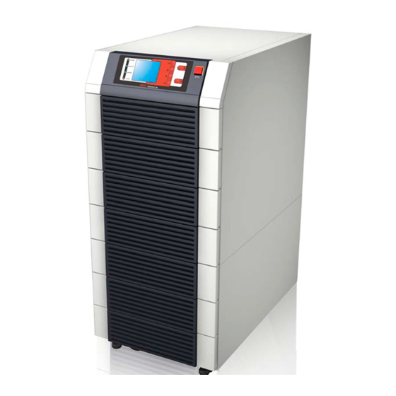
3. General View 3-1. Appearance LCD Display and Control Panel... -
Page 15: Dimensions (80Kva)
3-1-1 Dimensions (80kVA) Fig. 3-1 Power Unit 80kVA Fig. 3-2 External Battery Pack 80 kVA cabinet size... -
Page 16: Dimensions (120Kva)
3-1-2 Dimensions (120kVA) Fig. 3-3 Power Unit 120 kVA Fig. 3-4 External Battery Pack 120 kVA cabinet size... -
Page 17: Function Introduction
3-2 Function Introduction 3-2-1 Front Panel LCD Display Control Panel Status LED Indicators Power Modules I/P and O/P Protectors 1. LCD Display and Control Panel / Status LED indicators - UPS status and message display. - Parameter settings and button control. - UPS startup / shutdown. -
Page 18: Rear Panel
3-2-2 Rear Panel Interface Power Modules Wiring Terminal Block Caster & Stop Fig. 3-5 Rear view of Protect 3.M 2.0 80kVA 1. Interfaces Provide multi-interface for monitoring and control purpose. There are: (1) Two multi-function slots (SNMP Adapter, Relay I/O control card and Mobus card are optional accessories). -
Page 19: External Battery Cabinet - Rear Panel
Different regions may have their own markings of power phases. The following table is a cross reference for possible use. Three Phase America / Asia Europe 4. Caster & Stop: Move the UPS for short distance. Casters with stop function. Adjustable leveler for stabilization. - Page 20 4. Wiring Terminal Block You can remove the cover to perform the connection. Terminal: Positive(+), negative(-) and neutral (N). Two blocks for connecting the UPS and the next battery cabinet. Note: For longer autonomy times you can connect up to 4 battery cabinets in parallel.
-
Page 21: Power Module
3-2-4 Power Module Each power module is an independent 20kVA/16kW unit, consisting of a power factor corrected rectifier, a battery charger and an inverter, with associated monitoring and control circuitry. Status LED Fail Locking Latch Fig. 3-7 Front View of Power Module Fig. -
Page 22: Interface
3-3 Interface Smart Card Slot P3 P4 PARALLEL PARALLEL RS232 OUTPUT DRY CONTACT RS232 Port Interface for UPS parallel operation Dry Contact Output Dry Contact Input Fig. 3-10 Interface 3-3-1 Dry Contact Input P1: REPO (Remote Emergency Power Off) P2: Dry contact input (Two sets) P3: External Battery Cabinet Temperature 1 P4: External Battery Cabinet Temperature 2 P5: External Battery Cabinet Temperature 3... - Page 23 2. P2: Dry Contact Input (Two sets) The Protect 3.M 2.0 UPS provides two sets of dry contact input to receive external signals and then the UPS can take corresponding response. These contacts belong to “normal open” type. Fig. 3-12 Dry Contact Input 3.
-
Page 24: Dry Contact Output
3-3-2 Dry Contact Output COMM_A +12VS DRYA_NO DRY1 COMM_B +12VS DRYB_NO DRY2 COMM_C +12VS DRYC_NO DRY3 COMM_D +12VS DRYC_NO DRY4 COMM_E +12VS DRYE_NO DRY5 COMM_F +12VS DRYF_NO DRY6 Fig. 3-13 Dry Contact Output 3-11... - Page 25 The Protect 3.M 2.0 Series UPS provides 6 dry contact outputs. These contacts can be set to normally open or normally close. The default message is shown in the table below. Contact Message Description Pin1-2 Load on inverter The UPS is working normally. Pin3-4 Load on auto bypass The UPS is in bypass mode.
-
Page 26: Rs232 Port
Max. length of the parallel cable: 10 meters. 3-3-5 Smart Card Slot The Protect 3.M 2.0 Series UPS provides two smart slots. AEG offers many powerful smart cards for various applications. There are 4 accessories available as below. Smartcard Part-No. -
Page 27: Snmp Adapter Pro
- SNMP-Adapter PRO (Part-No.: 6000001271) Features: RJ45-Network Port Prepared to connect up to 4 external dry contacts for additional signalling Prepared to connect an external temperature and humidity sensor (8000022493) Agent for RFC1628 MIB UPS standard MIB ... -
Page 28: Snmp Adapter
Technical Data: Network Line connection RJ-45 (10/100MBits) Temperature 0~40 °C 10~80 % (rel.) Humidity 12 V DC Operation Voltage Dimensions (D x W x H) 130 x 60 x15 mm 66 g Weight - SNMP-Adapter (Part-No.: 6000004036) Same features as SNMP Adapter but only including RJ-45 Network plug in connector. -
Page 29: Programmable Relay I/O Card
3- Programmable Relay I/O Card (Part No.: 6000008721) Features: 6 output and 1 input dry contact Outputs configurable Input for UPS shutdown or Battery Test Configuration over RS 232 terminal server Output contact rating: 24VDC, 1A Input rating: 24V, 10mA Technical Specification Input Power 8 ~ 20VDC... - Page 30 I/O Definition GND-R: Relay Grounding Common: 12 ~ 24VDC Default Summary Alarm Input Power Fail Battery Low UPS in Bypass Mode Overload Over Temperature Input: Remote shutdown or battery test Tx: Transmit to PC, connect to RS232 pin-2. Rx: Receive from PC, connect to RS232 pin-3. GND-C: Ground for configuration, connect to RS232 pin-5.
-
Page 31: Modbus Card
ModBUS Card (Part No.: 6000008723) Features: Translate the UPS RS232 protocol into another RS232 and RS422/485 Modbus protocol. Device ID is adjustable by 8 dip switches. The value is from 0 to 255. The RS422/485 terminal resistor is selectable by using dip-switches and easy to install. -
Page 32: Additional Options
3-3-6 Additional Options The Protect 3.M 2.0 Series UPS is optional able to measure the battery current and makes it available in the measuring values which can be displayed (see also Page 7-10 “Measurements”). Therefore you have to add the option “Battery Current Measurement”... -
Page 33: Technical Specification
3-4 Technical Specification Capacity 80kVA/64KW 120kVA/96KW 220/380, 230/400, 240/415 Rating Voltage (3Φ 4W+Earth) Voltage Regulation -25 ~ +20 Input Current Harmonic Distortion Input < 5 (Full Load) PFC (Full Load) > 0.99 Frequency 50 / 60 Frequency Tolerance 45 ~ 65 Output Voltage 220/380, 230/400, 240/415 (3Φ... -
Page 34: Before Installation
4. Installation and Wiring 4-1 Before Installation Due to different installation environment, we strongly recommend that you read this manual carefully before installation. Only qualified service personnel can perform installation and maintenance. 4-2 Package Inspections External There are some unpredictable situations that can be possibly encountered during UPS transportation. -
Page 35: Storing Conditions Before Installation
4-3 Storing Conditions before Installation 1. If you have received the UPS and do not perform the installation immediately, be sure to store the UPS under: Temperature below 40°C Relative humidity below 90% 2. If the period of UPS installation is over 6 months, be sure to charge batteries for at least 8 hours before the first use. -
Page 36: Unpacking Procedure
4-4 Unpacking Procedures 4-4-1 Protect 3.M 2.0 80 kVA... -
Page 37: Protect 3.M 2.0 120 Kva
4-4-2 Protect 3.M 2.0 120 kVA... -
Page 38: Installation Environment
4-5 Installation Environment 4-5-1 Handling Safety 1. The Protect 3.M 2.0 Series UPS is equipped with casters so that you can roll the UPS in a short distance to the desired location. During unpacking process, be sure to make full use of manpower and a suitable machine (such as stacker) with sufficient capacity to carefully move the UPS. - Page 39 Table 4-1 Floor Loading for 80 kVA UPS Input: 230/400 Vac / Output: 230/400 Vac Capacity (KVA) Max Weight (Kg) Floor Loading (kg/㎡) Table 4-2 Floor Loading for External Battery Pack (80 kVA cabinet size) Batteries - 40 pcs Capacity (Ah) 12V/26AH 487,5...
-
Page 40: Environment
4. Attach the balance supporter to the UPS with bolts. Balance Supporter The UPS may topple over under unexpected conditions without balance supporter. Be sure to mount two balance supporters on both sides of the UPS for safety reasons. 4-5-3 Environment 1. -
Page 41: Preparations
4-6 Wiring 4-6-1 Preparations 1. The UPS should only be installed by a qualified electrically employed person 2. De-energize all input (AC or DC) or output power of the UPS before installing cables or making any electrical connection. 3. Ensure that all cables are correctly marked according to the purpose, as well as polarity, phase and diameter. - Page 42 Wrong cabling may burn the UPS and will result in severe accidents or damages. Due to the dimensioning of the battery cables we suggest to choose a cross section according to the maximum UPS power per cabinet. For example use for an 80 kVA cabinet always 50mm²...
- Page 43 4-6-2 Wiring (Single Unit, 80kVA model shown) Wiring procedure: Remove Cover Main AC Input Bypass Input External Battery Output Grounding Terminal Fig. 4-1 Wiring Terminal 1. Remove the terminal cover at the rear side. See Fig. 4-1. 2. You can see the terminal block with marks as below. ...
- Page 44 6. Confirm if the manual bypass circuit breaker (Q3) is cut off. 7. Confirm if the output circuit breaker (Q4) of UPS is cut off. 8. According to UPS model you have selected, use suitable cables and lugs (Refer to Table 4-3).
-
Page 45: Connecting External Battery Cabinet
4-6-3 Connecting External Battery Cabinet 2 40VDC 240VDC 240VDC 240VDC Battery Cabinet Fig. 4-3 Wiring of External Battery Cabinet – Connect corresponding terminals ( , N, ) between UPS and external battery cabinet. 4-12... -
Page 46: Wiring (Parallel Redundancy, Single Input)
4-6-4 Wiring (Parallel Redundancy, Single Input) 1. Confirm if the input and bypass input breaker (Q1 and Q2) are cut off (Refer to Fig. 4-2). 2. Confirm if the manual bypass circuit breaker (Q3) is cut off. 3. Confirm if the output breaker (Q4) is cut off. 4. -
Page 47: Wiring (Parallel Redundancy, Dual Input)
4-6-5 Wiring (Parallel Redundancy, Dual Input) 1. Confirm if the input and bypass input breaker (Q1 and Q2) are cut off (Refer to Fig. 4-2). 2. Confirm if the manual bypass circuit breaker (Q3) is cut off. 3. Confirm if the output breaker (Q4) is cut off. 4. -
Page 48: Operating Procedure
5. Operating Procedures 5-1 Startup Procedures (Single Unit) Before starting up the UPS system, be sure to check the following items first. Ensure all circuit breakers are cut off and switched to OFF, as well as the breaker or fuse of the external battery cabinet. ... -
Page 49: Battery Startup Procedures (Single)
If the conditions mentioned above are satisfied, follow the steps below to start If there is an external battery cabinet, switch the circuit breaker of battery cabinet to ON and confirm if manual bypass protection circuit breaker Q3 is cut off and switched to OFF. -
Page 50: Manual Bypass Startup (Single)
5-4 Manual Bypass Startup (Single Unit) If the UPS is in normal mode, press the “O” button for 3 seconds until you hear a “beep” and then release the button. The LCD screen will show “SHUTDOWN UPS?”, then select “YES” and press “ ”... -
Page 51: Startup Procedure (Parallel Redundancy)
5-5 Startup Procedures (Parallel Redundancy) Before starting up the UPS system, be sure to check the following items first. All circuit breakers are cut off and switched to OFF, as well as the breaker or fuse of the external battery cabinet. ... - Page 52 2. Switch off “Q1” and “Q4” of the UPS that you want to shut down. 3. Switch off “Q2” of the UPS that you want to shut down. 4. When all the power modules complete the discharging procedures, the LCD screen will be off.
-
Page 53: Manual Bypass Startup (Parallel Redundancy)
5-7 Manual Bypass Startup Procedures (Parallel Redundancy) 1. Only for maintenance purpose, you can manually turn on the bypass switch. If you switch on Q3 under normal status, the inverter will shut down and the output will be supplied by manual bypass source. 2. - Page 54 5-7-2 Transferring from Manual Bypass Mode to Online Mode 1. Switch on the battery circuit breaker of external battery cabinet. 2. Switch on ”Q2” and ”Q4” of both UPSs. Switch off ”Q3” of both UPSs. The LCD screens of both UPSs show ”ON AUTO BYPASS”.
-
Page 55: Power Module Replacement
6. Power Module Replacement 6-1 Status LED Indicators for Power Module Each power module features one LED to help inform the user about the power module status. LED status: “OFF”: When the locking latch is located at “”, the power module is inactive. When the locking latch is located at “”... -
Page 56: Power Module Replacement
6-2 Power Module Replacement WARNING! Only trained persons familiar with the construction and operation of the equipment, as well as the electrical and mechanical hazards involved, may install and remove system components. WARNING! Before removing any Power Module, ensure that the remaining Power Modules can support the load. - Page 57 Fail On Fail On...
-
Page 58: Display And Configuration
7. Display and Configuration 7-1. Control Panel Fig. 7-1 Control Panel 1. Normal (Green): Lights on when the UPS input power is normal. 2. Battery (Amber): Lights on when the UPS is in backup mode. 3. Bypass (Amber): Lights on when the UPS is in bypass mode. 4. -
Page 59: Lcd Display
7-2 LCD Display Protect 3.M 2.0 Series UPS features a user-friendly LCD screen to show messages. 7-2-1 LCD Display Hierarchy Fig. 7-2 LCD Display Hierarchy... -
Page 60: Default Screen
7-3 Default Screen After the UPS starts up and completes the self test, the screen will show as below. 1. When any event occurs, you will see the sign “!” flashes. You can press “” to see the details. For example: Press “”... -
Page 61: Status Display
7-3-1 Status Display The LCD screen will show different status of the UPS. UN I T : # 1 . 1 L OAD NO P OWE R E D 2 0 0 8 - 1 0 - 0 2 1 1 : 5 9 : 5 9 BYPA. - Page 62 UN I T : # 1 . 1 S E L F D I GNO S I S 2 0 0 8 - 1 0 - 0 2 1 1 : 5 9 : 5 9 BYPA. MAINS T O B R OWS E E V E N T ( 0 0 4 ) This message means the UPS starts up by battery power (“Black Start”).
-
Page 63: Battery Power
UN I T : # 1 . 1 L OAD P R O T E C T E D 2 0 0 8 - 1 0 - 0 2 ON L I N E 1 1 : 5 9 : 5 9 BYPA. - Page 64 UN I T : # 1 . 1 L OAD P R O T E C T E D 2 0 0 8 - 1 0 - 0 2 B A T T E S T 1 1 : 5 9 : 5 9 BYPA.
- Page 65 UN I T : # 1 . 1 L OAD UN P R O T E C T E D 2 0 0 8 - 1 0 - 0 2 ON MANUA L B Y P A S S 1 1 : 5 9 : 5 9 BYPA.
-
Page 66: Main Menu
7-4 Main Menu Press “ ” in default screen will change to the main menu. UN I T : # 1 . 1 L OAD UN R O T E C T E D 2 0 0 8 - 1 0 - 0 2 ON AU T O B Y P A S S 1 1 : 5 9 : 5 9... - Page 67 MEASURE Use “” or ”” to select “Measure”, then press ” ” to confirm. Use “” or ”” to see all the UPS status. UN I T : # 1 . 1 UN I T : # 1 . 1 L OAD UN R O T E C T E D 2 0 0 8 - 1 0 - 0 2...
-
Page 68: Ups Setup
7-5 UPS SETUP UN I T : # 1 . 1 L OAD UN R O T E C T E D 2 0 0 8 - 1 0 - 0 2 ON AU T O B Y P A S S 1 2 : 0 9 : 4 9 Use “”... -
Page 69: Bypass Setup
a. BYPASS SETUP Use “” or ”” to select “BYPASS”, then press ” ” to confirm. UN I T : # 1 . 1 1. Use “” or ”” to select “VOLT L OAD UN R O T E C T E D 2 0 0 8 - 1 0 - 0 2 RANGE”... -
Page 70: Output Setup
b. OUTPUT SETUP Use “” or ”” to select “OUTPUT SETUP”, then press ” ” to confirm. All parameters in this segment can only be changed under “Bypass Mode”. UN I T : # 1 . 1 1. Use “” or ”” to select the desired L OAD UN R O T E C T E D 2 0 0 8 - 1 0 - 0 2... -
Page 71: Eco Mode
UN I T : # 1 . 1 4. ECO mode L OAD UN R O T E C T E D 2 0 0 8 - 1 0 - 0 2 Use “” or ”” to select the desired ON AU T O B Y P A S S 1 1 : 5 9 : 5 9... -
Page 72: Battery Setup
c. BATTERY SETUP Use “” or ”” to select “BATTERY”, then press ” ” to confirm. All parameters in this segment can only be changed under “Bypass Mode”. 1. Use “” or ”” to select the desired item, then press ” ”... - Page 73 4. Battery Install Date UN I T : # 1 . 1 L OAD UN R O T E C T E D 2 0 0 8 - 1 0 - 0 2 Use “” or ”” to set the installation ON AU T O B Y P A S S 1 1 : 5 9 : 5 9...
-
Page 74: Charger Setup
d. CHARGER SETUP Use “” or ”” to select “CHARGER”, then press ” ” to confirm. UN I T : # 1 . 1 1. Press ” ” to set the charging L OAD UN R O T E C T E D 2 0 0 8 - 1 0 - 0 2 current. -
Page 75: Parallel Setup
e. PARALLEL SETUP Use “” or ”” to select “PARALLEL”, then press ” ” to confirm. UN I T : # 1 . 1 1. Use “” or ”” to select L OAD UN R O T E C T E D 2 0 0 8 - 1 0 - 0 2 ON AU T O B Y P A S S... -
Page 76: Control & Test Setup
f. CONTROL & TEST SETUP Use “” or ”” to select “CONTROL & TEST”, then press ” ” to confirm. UN I T : # 1 . 1 1. Use “” or ”” to select the desired L OAD UN R O T E C T E D 2 0 0 8 - 1 0 - 0 2 item, then press ”... - Page 77 UN I T : # 1 . 1 L OAD UN R O T E C T E D 2 0 0 8 - 1 0 - 0 2 5. Force Boost Charge ON AU T O B Y P A S S 1 1 : 5 9 : 5 9 Press ”...
-
Page 78: Local Setup
g. LOCAL SETUP Use “” or ”” to select “LOCAL SETUP”, then press ” ” to confirm. UN I T : # 1 . 1 1. Use “” or ”” to select the desired L OAD UN R O T E C T E D 2 0 0 8 - 1 0 - 0 2 ON AU T O B Y P A S S... - Page 79 UN I T : # 1 . 1 5. LCD Contrast L OAD UN R O T E C T E D 2 0 0 8 - 1 0 - 0 2 Use “” or ”” to set the contrast of ON AU T O B Y P A S S 1 2 : 1 9 : 5 9...
-
Page 80: Maintenance
7-6 Maintenance Use “” or ”” to select ”MAINTENANCE” in the main menu, then press “ ” to confirm. The first item is the series number of the UPS unit. UN I T : # 1 . 1 1. Use “” or ”” to select the desired L OAD UN R O T E C T E D 2 0 0 8 - 1 0 - 0 2... -
Page 81: Event Log
UN I T : # 1 . 1 4. Event Log L OAD UN R O T E C T E D 2 0 0 8 - 1 0 - 0 2 Use “” or ”” to read the event log, ON AU T O B Y P A S S 1 1 : 5 9 : 5 9...