Table of Contents
Recommended
Find the latest version of this and other Performance Series IP camera
documents on the Honeywell Video website. Go to
http://www.honeywellvideo.com/products/cameras/ip/index.html
find your camera and view/download the latest documentation.
Refer to the Honeywell Open Technology Alliance to learn more
about our open and integrated solutions (go to:
http://www.security.honeywell.com/hota/).
Performance Series
Software Configuration
IP Cameras
HED1PR3
HED3PR3
H4D3PRV3
H4D3PRV2
HBD1PR1
HBD3PR1
HBD3PR2
Guide
to
Document 800-21358 – Rev A – 10/2015
Table of Contents

Related Manuals for Honeywell Performance HED1PR3


Summary of Contents for Honeywell Performance HED1PR3
-
Page 1: Software Configuration
Honeywell Video website. Go to http://www.honeywellvideo.com/products/cameras/ip/index.html find your camera and view/download the latest documentation. Refer to the Honeywell Open Technology Alliance to learn more about our open and integrated solutions (go to: http://www.security.honeywell.com/hota/). Document 800-21358 – Rev A – 10/2015... - Page 2 Revisions Issue Date Revisions 10/2015 New document.
-
Page 3: Cautions And Warnings
Cautions and Warnings WARNING Installation and servicing should be performed only by qualified and experienced technicians to conform to all local codes and to maintain your warranty. WARNING To ensure compliance with electrical safety standards this product is intended for use with a Listed Power Adapter marked with “Limited Power Source”, “LPS”, on the unit, output rated 12 V DC, minimum 0.7A, Tma=60°C or from Power over Ethernet (PoE) provided by Listed Information Technology... - Page 4 The equipment supplied with this guide meets the provisions of the following European Union council directives: • 2014/30/EU for EMC • 2001/95/EC for safety, and • 2011/65/EU for RoHS compliance. WARNING To comply with EN50130-4 requirements, a UPS should be employed when powering the camera from 24 V AC. www.honeywell.com/security...
-
Page 5: Safety Instructions
Waste Electrical and Electronic Equipment (WEEE) Correct Disposal of this Product (applicable in the European Union and other European countries with separate collection systems). This product should be disposed of, at the end of its useful life, as per applicable local laws, regulations, and procedures. Safety Instructions Before installing or operating the unit, read and follow all instructions. -
Page 6: Warranty And Service
Honeywell will repair or replace, at its sole option, free of charge, any defective products returned prepaid. In the event you have a problem with any Honeywell product, please call Customer Service at 1.800.323.4576 for assistance or to request a Return Merchandise Authorization (RMA) number. -
Page 7: Table Of Contents
Contents | 7 Contents About This Document ..........Overview of Contents. - Page 8 Manually Configuring the DDNS ........62 Using Honeywell DDNS to Configure DDNS ......63 IP Filter .
- Page 9 Contents | 9 Configuring for Micro SD Card Abnormalities ......89 Configuring for Network Abnormalities Such as Network Disconnections and IP Conflicts . . . 91 Configuring for Illegal Access .
- Page 10 10 | Performance Series IP Camera Software Configuration Guide www.honeywell.com/security...
- Page 11 Figures | 11 Figures Figure 1-1 HED1PR3/HED3PR3 Dimensions ....... . . 21 Figure 1-2 HED1PR3/HED3PR3 Components .
- Page 12 DDNS Configuration Interface ........62 Figure 5-13 Using Honeywell DDNS to Configure DDNS ......63 Figure 5-14 IP Filter Configuration Interface .
- Page 13 Figures | 13 Figure 6-4 Tampering Configuration Interface ....... . 88 Figure 6-5 Tampering Working Period Configuration Interface.
- Page 14 14 | Performance Series IP Camera Software Configuration Guide www.honeywell.com/security...
- Page 15 Table 5-10 Honeywell DDNS Configurations ........63 Table 5-11 SMTP (Email) Configurations.
- Page 16 16 | Performance Series IP Camera Software Configuration Guide www.honeywell.com/security...
-
Page 17: About This Document
| 17 About This Document This document provides instructions for accessing, configuring, and operating the Performance Series IP cameras. This document is intended for system installers, administrators, and operators. Overview of Contents This document contains the following chapters and appendixes: •... -
Page 18: Typographical Conventions
Buttons you click to perform actions Click Exit to close the program. Italic Placeholders: words that vary depending on the Enter your user name. situation Cross-reference to external source Refer to the System Administrator Guide. Cross-reference within document Chapter 2, Installation. www.honeywell.com/security... -
Page 19: Introduction
Camera Dimensions, page 21 Overview Honeywell’s Performance Series IP cameras integrate traditional camera and network video technology, combining video data collection and transmission. These flexible, fully featured cameras are the ideal choice for a wide range of indoor and outdoor surveillance applications. -
Page 20: Key Features
• Device management via Internet or client PC User Management • Each user belongs to specific group • Different user rights for each group • User rights cannot exceed group rights System Management • Log function • System resource information and running real-time status display www.honeywell.com/security... -
Page 21: Camera Dimensions
Introduction | 21 Camera Dimensions This section displays the dimensions and main components/connectors of each Performance Series IP camera. HED1PR3/HED3PR3 Ball Cameras Figure 1-1 HED1PR3/HED3PR3 Dimensions Figure 1-2 HED1PR3/HED3PR3 Components Lens Camera module Camera enclosure LAN connector 12 V DC connector 800-21358 - A - 10/2015... -
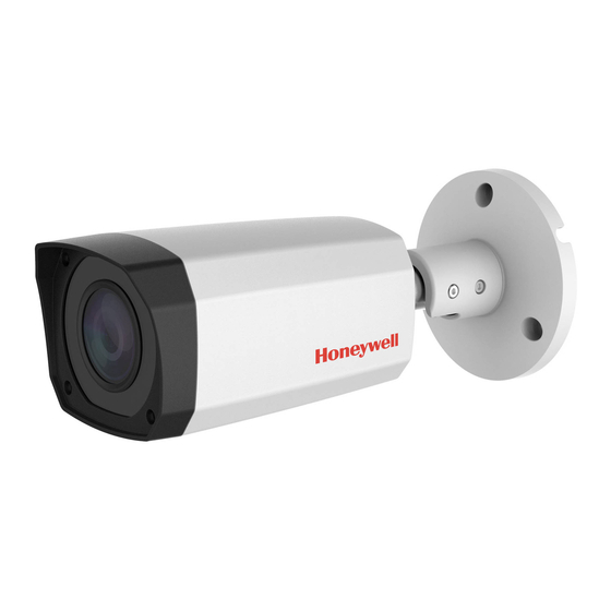
Page 22: Hbd1Pr1/Hbd3Pr1 Bullet Cameras
22 | Performance Series IP Camera Software Configuration Guide HBD1PR1/HBD3PR1 Bullet Cameras Figure 1-3 HBD1PR1/HBD3PR1 Dimensions Figure 1-4 HBD1PR1/HBD3PR1 Connections LAN connector 12 V DC connector www.honeywell.com/security... -
Page 23: Hbd3Pr2 Bullet Camera
Introduction | 23 HBD3PR2 Bullet Camera Figure 1-5 HBD3PR2 Dimensions Figure 1-6 HBD3PR2 Connections LAN connector 12 V DC connector 800-21358 - A - 10/2015... -
Page 24: H4D3Prv2 Mini Dome Camera
24 | Performance Series IP Camera Software Configuration Guide H4D3PRV2 Mini Dome Camera Figure 1-7 H4D3PRV2 Dimensions Figure 1-8 H4D3PRV2 Components Camera module Camera enclosure LAN connector 12 V DC connector www.honeywell.com/security... -
Page 25: H4D3Prv3 Mini Dome Camera
Introduction | 25 H4D3PRV3 Mini Dome Camera Figure 1-9 H4D3PRV3 Dimensions Figure 1-10 H4D3PRV3 Components Camera module Camera enclosure LAN connector 12 V DC connector 800-21358 - A - 10/2015... - Page 26 26 | Performance Series IP Camera Software Configuration Guide www.honeywell.com/security...
-
Page 27: Getting Started
Before you can start using your camera, you must install the ConfigTool IP utility on your PC. Insert the software CD that came with your camera into your PC’s disk drive. Open the Honeywell Config Tool folder, and then double-click Honeywell ConfigTool.exe. On the ConfigTool welcome screen, click Next. -
Page 28: Discovering Your Device On The Network
1234), and then click OK. Figure 2-1 Log In to a Device On the Config screen, click the Net tab, type the new IP settings in the IP Address, Subnet Mask, and Gateway fields, and then click Save. www.honeywell.com/security... -
Page 29: Upgrading Your Device's Firmware
Getting Started | 29 Figure 2-2 Network Settings Upgrading Your Device’s Firmware Before you begin using your camera, make sure you have the latest firmware installed. You can upgrade a single device or multiple devices at the same time. To upgrade a single device: From the list of devices in ConfigTool, click the device that you want to upgrade. -
Page 30: Figure 2-4 Select Batch Mode
From the list of devices, click all of the devices that you want to upgrade, and then click Start. Figure 2-5 Batch Mode Screen On the Batch Upgrade screen, click Open, navigate to the directory that contains the firmware file, and then click OK. www.honeywell.com/security... -
Page 31: Opening A Web Client
Getting Started | 31 Figure 2-6 Batch Upgrade Dialog Box When the upgrade is complete, the devices will reboot. While a device is rebooting, the message "Device is offline: [device IP address]" appears. Opening a Web Client You can configure individual camera settings using the web client. To open the web client from ConfigTool, click the device that you want to open a web client for, and then, in the Operate column, click the Microsoft Internet Explorer icon. - Page 32 32 | Performance Series IP Camera Software Configuration Guide www.honeywell.com/security...
-
Page 33: Logging In And Viewing Live Video
Logging In and Viewing Live Video This chapter contains the following sections: • Logging In to the Camera via the Web Client, page 33 • Using the Live View Interface, page 35 Logging In to the Camera via the Web Client Using the web client, you can monitor live video, play back recorded video, and configure camera settings. -
Page 34: Installing The Browser Plug-In
Click Please click here to download and install the plug-in. A File Download-Security Warning popup message appears (Figure 3-3) that asks if you would like to run or save this file. Figure 3-3 File Download Security Warning Message for the Plug-in www.honeywell.com/security... -
Page 35: Using The Live View Interface
Logging In and Viewing Live Video | 35 Click Run. An Internet Explorer - Security Warning appears. Figure 3-4 Internet Explorer - Security Warning Click Run to start the installation. A Ready to Install window appears. Click Install. A progress window appears. When the plug-in installation is complete, the installation page automatically closes. -
Page 36: Video Encoder Settings
Live View Controls From the Live View controls toolbar, you can zoom in on a scene, take a snapshot, or manually record video. These controls are described in more detail below. Figure 3-8 Live View Window Controls www.honeywell.com/security... -
Page 37: Live View Window Configuration
Logging In and Viewing Live Video | 37 Table 3-2 Live View Window Controls Icon Control Description While viewing live video, click and hold down the left mouse button to zoom in on a specific area. Digital Zoom Right-click the mouse to return to the previous magnification. -
Page 38: Table 3-3 Live View Window Configuration Tools
(however, there may be a decrease in image quality). Zoom and Focus Note This option is available only for HBD3PR2 and H4D3PRV2 cameras. Click to open the Zoom and Focus panel. Drag the sliders to adjust the zoom and focus, and then click Auto Focus. www.honeywell.com/security... -
Page 39: Playing Back Video (Hbd3Pr2/H4D3Prv2 Only)
Playing Back Video (HBD3PR2/H4D3PRV2 only) This chapter contains the following sections: • Introduction, page 39 • Playing Back Recorded Video, page 40 • Using the Playback Assistant, page 43 • Creating a Video Clip, page 44 • Viewing Snapshots, page 44 Introduction This chapter describes how to play back recorded video and saved snapshots on HBD3PR2/H4D3PRV2 cameras using the web client, how to zoom in and take snapshots while... -
Page 40: Overview Of The Playback Interface
Searching for a File by Recording Type on page Timeline configuration (see Timeline Configuration on page Playback Assistant (see Using the Playback Assistant on page Playing Back Recorded Video Note Playback is currently only supported for HBD3PR2/H4D3PRV2 cameras. Playback Controls Figure 4-2 Playback Controls www.honeywell.com/security... -
Page 41: Playing A Recorded File From The Calendar
Playing Back Video (HBD3PR2/H4D3PRV2 only) | 41 Table 4-1 Playback Controls Control Description Click to play video. While in Play mode, this button changes to the Pause button. Click to stop video playback. Click to go to the next frame. Note Video playback must be paused before you can use this function. -
Page 42: Figure 4-4 Recording Timeline
Click the download button to download the dav file to the local computer. Click to return to the calendar interface. Note On the playback file interface, you can download a file to your local computer. Note Select dav for the recording type because MP4 is not supported. www.honeywell.com/security... -
Page 43: Searching For A File By Recording Type
Playing Back Video (HBD3PR2/H4D3PRV2 only) | 43 Searching for a File by Recording Type By selecting a recording file type, you can filter by a particular recording type so that the timeline and file list display only those types of recorded files. You can also select the record type to display in the Live View window. -
Page 44: Creating A Video Clip
. This designates the end time of the clip. Click to save the clipped file to your local PC. To configure the saving path, see Path on page Viewing Snapshots Note Viewing snapshots is currently only supported for HBD3PR2/H4D3PRV2 cameras. www.honeywell.com/security... -
Page 45: Figure 4-9 Snapshot Playback Control Interface
Playing Back Video (HBD3PR2/H4D3PRV2 only) | 45 Figure 4-9 Snapshot Playback Control Interface Playback file bar Play function bar Snapshot type bar In the Playback interface, in the calendar area, do the following: In the File Type box, select jpg. In the Data Src box, select SD Card. - Page 46 If you want, you can refine your search results further by entering a specific time range to search. To view a snapshot, double-click the file name (start time). To download a snapshot to your local PC, click the download button next to the file name. To configure the saving path, see Path on page www.honeywell.com/security...
-
Page 47: Configuring Camera Settings
Configuring Camera Settings This chapter contains the following sections: • Configuring Camera Settings, page 47 • Configuring Network Settings, page 58 • Configuring Storage Settings, page 70 • Configuring System Settings, page 75 • Viewing System Information, page 82 Configuring Camera Settings Conditions On the Conditions tab, you can view camera property information. -
Page 48: Figure 5-1 Camera Setup Window
Choosing a higher value can introduce video noise to the image. Gamma Adjusts dynamic range. Choosing a higher value increases the brightness of the image non-linearly. Select from 0 to 100. The recommended range is between 40 and 60. The default value is 50. www.honeywell.com/security... - Page 49 Configuring Camera Settings | 49 Table 5-1 Camera Configurations (cont’d) Parameter Function Anti-flicker Outdoor: In Outdoor mode, you can select any exposure mode to avoid flicker. 50Hz: When the current is 50Hz, the system can automatically adjust the exposure according to the environment’s brightness to prevent stripes in the video.
- Page 50 50 when HLC is turned on. HLC is enabled only when Anti-flicker is set to Outdoor, and the Exposure is set to Auto. Mirror Click to switch the video from left to right. This function is disabled by default. www.honeywell.com/security...
-
Page 51: Profile Management
Configuring Camera Settings | 51 Table 5-1 Camera Configurations (cont’d) Parameter Function Flip No Flip: This is the default setting. Flip 180°: Flips the video 180°. Flip 90°: Rotates the video by 90°. Flip 360°: Rotates the video by 360°. 3D Noise 3D noise reduction is enabled by default. -
Page 52: Zoom And Focus
Click to adjust the focus automatically. Restore All Click to reset the lens to 0 position. Note Reset the lens periodically if you are making a lot of zoom and focus adjustments. Refresh Refreshes the video image that is displayed. www.honeywell.com/security... -
Page 53: Video Configuration
Configuring Camera Settings | 53 Video Configuration Video Bit Stream Figure 5-4 Video Bit Stream Configuration Window Table 5-3 Video Bit Stream Configurations Parameter Function Select from General stream and Motion stream. You can select different encoder frame rates for different recording events. The system supports the Active Control Frame (ACF) function. - Page 54 Set the number of P-frames between I-frames. The value ranges from 25 to 150. The default value is 50. I Frame Interval The recommended value for I Frame Interval is 2 times the frame rate setting. www.honeywell.com/security...
-
Page 55: Snapshot
Configuring Camera Settings | 55 Snapshot Figure 5-5 Snapshot Configuration Interface Table 5-4 Snapshot Configurations Parameter Function Shapshot Type Select from either General (schedule) or Event (activation). Image Size Same as the main stream resolution. Quality Select from six levels of image quality. Interval Set the snapshot frequency from 1s to 7s. -
Page 56: Video Overlay
Enable this function to overlay text in the video window. Enter the Text Overlay text to be overlayed in the Input field and select Right or Left alignment from the drop-down menu. Note ROI is only available for HED3PR3, HBD3PR1, H4D3PRV3, H4D3PRV2, and HBD3PR2 cameras. www.honeywell.com/security... -
Page 57: Path
Storage Path Interface Set the storage path for snapshots ( in the live interface) and for recorded video ( the live interface). The default path for snapshots is C:\Honeywell Video Systems\LiveSnapshot. The default path for recorded video is C:\Honeywell Video Systems\LiveRecord. -
Page 58: Configuring Network Settings
Address, Subnet mask, and Default Gateway. If DHCP mode is selected, the IP Address, Subnet mask, and Default Gateway are assigned automatically. Note IP Address, Subnet mask, Default Gateway, and DHCP are read-only when PPPoE is enabled. MAC Address Displays the MAC address. www.honeywell.com/security... - Page 59 Configuring Camera Settings | 59 Table 5-7 TCI/IP Configuration Parameter Function IP Version Select the IP version you are using: IPv4 or IPv6. If Static mode is selected, type values for the IP Address, Subnet IP Address mask, and Default Gateway. Preferred DNS Enter the preferred DNS server IP address.
-
Page 60: Connection
Port: The default is 554. You can leave this field blank if you are using the default value. Follow standard RTP protocols. When the encode mode is MJPEG, the maximum supported resolution is 2040×2040. HTTPs Enable the HTTPs port. HTTPs Port The default is 443. www.honeywell.com/security... -
Page 61: Onvif
Configuring Camera Settings | 61 ONVIF ONVIF (Open Network Video Interface Forum) is a global open standard for the interface of IP-based security products. It covers network video mode, interface, data type, and data interaction mode. The ONVIF specification aims at interoperability of network video products regardless of manufacturer. -
Page 62: Ddns
Parameter Function Server Type You can select the DDNS protocol from the drop-down list, and then enable the DDNS function. Select the Honeywell DDNS server (which is free) to enable the DDNS function. Server Address The DDNS server IP address. -
Page 63: Using Honeywell Ddns To Configure Ddns
Configuring Camera Settings | 63 Using Honeywell DDNS to Configure DDNS Figure 5-13 Using Honeywell DDNS to Configure DDNS Set the DDNS to connect the Honeywell DDNS server so that you can access the system through the servers. Table 5-10 Honeywell DDNS Configurations... -
Page 64: Figure 5-14 Ip Filter Configuration Interface
MAC address must be in the same network subnet as the IP camera. CAUTION If you setup the IP Filter/Trusted sites options and forget the IP/MAC address that is allowed to access the camera, you will have to return the camera to the factory to repair the problem. www.honeywell.com/security... -
Page 65: Smtp (Email)
Configuring Camera Settings | 65 SMTP (Email) Figure 5-15 SMTP Configuration Interface Table 5-11 SMTP (Email) Configurations Parameter Function SMTP Server Enter the server address. Port The default setting is 25. You can modify this setting as necessary. Anonymity Supports the anonymity function for the server. You can automatically login anonymously. -
Page 66: Upnp
UPnP Configuration Interface Enabling UPnP in Windows When UPnP is enabled in Windows, the camera can be detected automatically through My Network Places. Note The UPnP are enabled by default on Windows 7 systems. This procedure applies to Windows XP. www.honeywell.com/security... -
Page 67: Bonjour
Configuring Camera Settings | 67 Go to Start Control Panel Add or remove programs. Click Add or remove programs, and then select Network Services from the Windows Components Wizard. Click Details, and then click to select Internet Gateway Device Discovery and Control client and UPnP User Interface. -
Page 68: Ieee802.1X
LAN. IEEE802.1X supports the client’s ability to manually choose how authentication works for accessing the LAN or not. IEEE802.1X supports the ability to: • authenticate • calculate the fee • ensure security • maintain requirements www.honeywell.com/security... -
Page 69: Qos
Configuring Camera Settings | 69 Figure 5-19 802.1X Configuration Interface Table 5-13 802.1X Configurations Parameter Function Authentication PEAP (protected EAP protocol) Username Enter a username to log in. This username is authenticated by the server. Password Enter a password. Quality of Service (QoS) is a network security mechanism. It fixes problems with network delay and jams. -
Page 70: Configuring Storage Settings
Recording Schedule Color Codes: • Green: General recording/snapshot • Yellow: Motion detection recording/snapshot Setting Holidays You can set specific days as holidays, for which the recording schedule is different. When enabled, the selected/configured dates will record according to the holiday setup. www.honeywell.com/security... -
Page 71: Destination
Configuring Camera Settings | 71 Figure 5-22 Holiday Schedule Destination Path On the Path tab, you can assign where recorded video files or snapshots will be saved. Depending on your camera model, you can save recorded video or snapshots to a Micro SD card, an FTP server, and/or an NAS disk. -
Page 72: Local
Local Storage Configuration Interface On the FTP tab, you can enable the FTP storage function. When enabled, event-triggered video and snapshots (either scheduled or motion detection, depending on what you chose in Figure 5-23) will be saved to the specified FTP server. www.honeywell.com/security... -
Page 73: Figure 5-25 Ftp Configuration Interface
Configuring Camera Settings | 73 Figure 5-25 FTP Configuration Interface Table 5-16 FTP Configurations Parameter Function Server Address Set the IP address of the server. Port The default setting is 21. You can modify this setting as necessary. User Name Enter the server user name. -
Page 74: Nas
Pack Duration Select the file size. The default is 8 minutes. Pre-event Record Enter a pre-record value. For example, the system can record the four seconds of video in the buffer. Recording begins five seconds before the event trigger. www.honeywell.com/security... -
Page 75: Configuring System Settings
Configuring Camera Settings | 75 Table 5-18 Record Control Configurations (cont’d) Parameter Function Disk Full Select Stop Recording or Overwrite the previous files when the HDD is full. Overwrite: If the current working HDD is full, then the system will overwrite the previous file. -
Page 76: Date And Time
( _ ) for the user or group name. You can configure up to 18 users and eight groups (default factory settings). The factory default setup includes two user levels: user and admin (case-sensitive). www.honeywell.com/security... -
Page 77: User Name
Configuring Camera Settings | 77 When configuring groups, you can configure the rights of those groups. You can also set rights for individuals within groups. Note User management adopts group/user modes. The user name and the group name should be unique. A user can be included in only one group at a time. User Name In the Username Configuration interface, you can enable anonymous login, add/remove users, and modify a username. -
Page 78: Figure 5-31 Add User Configuration Interface
Ensure that the general user has lower rights than the admin user. Note User rights cannot exceed the rights of the group to which that user belongs. Modifying Users: Click to modify a user’s properties, including their group, passwords, and rights. Figure 5-32 Modifying User Interface www.honeywell.com/security... -
Page 79: Group
Configuring Camera Settings | 79 Modifying a Password: Enter the old password once, and then enter the new password twice to confirm the new password. Click Save to save the new settings. Note Passwords can contain up to 32 characters, using numbers and letters only. Only users with account rights can modify other users’... -
Page 80: Restoring Default Settings
In the Modify Group Interface, you can edit Remarks and Rights. Restoring Default Settings Click Default to restore the camera to its factory default settings. Figure 5-36 Default Interface Note The system cannot reset some information, such as the network IP address. www.honeywell.com/security... -
Page 81: Import/Export
Configuring Camera Settings | 81 Import/Export Figure 5-37 Import/Export Configuration Interface Table 5-21 Import/Export Configurations Parameter Function Import Click to import local setup files to the system. Export Click to export the corresponding system setup to your local PC. Automatic Maintenance You can select either Auto Reboot, Auto Delete Old Files, or Manual Reboot. -
Page 82: Upgrade
Selecting the incorrect upgrade file might cause a camera malfunction. Viewing System Information Version In the Version interface, you can view the system hardware features, the software version, and the release date. This information is for reference only. Figure 5-40 Version Interface www.honeywell.com/security... -
Page 83: Log
Configuring Camera Settings | 83 Figure 5-41 Log Interface Table 5-22 Log Interface Configurations Parameter Function Start Time Configure the start time for the requested log. End Time Configure the end time for the requested log. Type Select a log type: System, Operation, Configuration Operation, Data Operation, Event Operation, Record Operation, Account Management, Log Clearing. -
Page 84: Figure 5-42 Online User Interface
84 | Performance Series IP Camera Software Configuration Guide Figure 5-42 Online User Interface www.honeywell.com/security... -
Page 85: Configuring Events And Alarms
Configuring Events and Alarms This chapter contains the following sections: • Configuring for Motion Detection on page 85 • Configuring for Camera Tampering on page 88 • Configuring for Abnormalities on page 89 • Configuring Alarms on page 92 Configuring Events Configuring for Motion Detection Video Motion Detection Figure 6-1... -
Page 86: Figure 6-2 Configuring The Working Period
Snapshot Check to enable the system to backup motion detection snapshot files. (See Path on page 71 for information about configuring where snapshots are saved.) Configuring the Working Period Figure 6-2 Configuring the Working Period www.honeywell.com/security... -
Page 87: Figure 6-3 Configuring The Motion Detection Area
Configuring Events and Alarms | 87 Configuring the Motion Detection Area Figure 6-3 Configuring the Motion Detection Area Table 6-2 Motion Detection Area Configurations Parameter Function Sensitivity Adjust the brightness sensitivity. You might need to increase the brightness sensitivity to trigger motion detection. You can configure up to four areas. -
Page 88: Configuring For Camera Tampering
The system will wait for the specified time before it begins recording. Select from 10s to 300s. Send Email When enabled, the system sends an email alert when an alarm occurs. Snapshot When enabled, the system automatically sends an email when an alarm occurs. www.honeywell.com/security... -
Page 89: Configuring For Abnormalities
Configuring Events and Alarms | 89 Figure 6-5 Tampering Working Period Configuration Interface Configuring for Abnormalities Abnormalities include No SD Card, Capacity Warning, SD Card Error, Disconnection, IP Conflict, and Unauthorized Access. Note Only cameras with Micro SD cards (HBD3PR2 and H4D3PRV2) can encounter the following abnormalities: No SD Card, Capacity Warning, and SD Card Error. -
Page 90: Figure 6-7 Sd Card Error Warning Configuration Interface
Click Enable so that an alarm is triggered when a Micro SD card error occurs. Click Email so that an email is sent to a specified receiver if a Micro SD card error occurs. Note Emails cannot be sent if the network is offline or if there is an IP conflict. www.honeywell.com/security... -
Page 91: Configuring For Network Abnormalities Such As Network Disconnections And Ip Conflicts
Configuring Events and Alarms | 91 Configuring for Network Abnormalities Such as Network Disconnections and IP Conflicts Figure 6-9 Dicsonnection Configuration Interface Figure 6-10 IP Conflict Configuration Interfacet Click Enable so that an alarm is triggered when there is a network disconnection or an IP conflict. -
Page 92: Configuring Alarms
Enter the number of times a user can attempt to log in. Select from 3 to 10. Click Email so that an email is sent to a specified receiver if someone attempts to illegally access the camera. Configuring Alarms Click the Alarm tab to open the alarm configuration interface. Figure 6-12 Alarm Configuration Interface www.honeywell.com/security... -
Page 93: Table 6-4 Alarm Configurations
Configuring Events and Alarms | 93 Table 6-4 Alarm Configurations Type Parameter Function System alarms when a motion detection alarm Motion Detection occurs. System alarms when the camera has been Tampering tampered with. System alarms when the disk (Micro SD card) is Alarm Type Disk Full full. - Page 94 94 | Performance Series IP Camera Software Configuration Guide www.honeywell.com/security...
-
Page 95: Appendix A Troubleshooting
Troubleshooting Refer to the following guidelines to troubleshoot any performance issues. If you require additional assistance, contact Honeywell Technical Support (see back cover for contact information). Cannot play downloaded file. • Use the player located on the CD that came with your camera. -
Page 96: Embedded Nvr Integration Capacity Matrix
32°F (0°C). • Use of a UPS power supply is strongly recommended. Embedded NVR Integration Capacity Matrix Refer to the following table when integrating Performance Series IP cameras with Honeywell Embedded NVRs. Table A-1 Embedded NVR Integration Matrix - Maximum Frame Rate and Resolution Part No. -
Page 97: Table A-1 Embedded Nvr Integration Matrix - Maximum Frame Rate And Resolution
Troubleshooting | 97 Table A-1 Embedded NVR Integration Matrix - Maximum Frame Rate and Resolution HEN08142(X) 25/30 fps @ 25/30 fps @ 25/30 fps @ 25/30 fps @ 25/30 fps @ 25/30 fps @ 25/30 fps @ 1280×960 1920×1080 1280×960 1920×1080 1920×1080 1920×1080... - Page 98 98 | Performance Series IP Camera Software Configuration Guide www.honeywell.com/security...
-
Page 99: Appendix B Camera Specifications
Camera Specifications HED1PR3/HED3PR3 Ball Cameras Table B-1 HED1PR3/HED3PR3 Specifications Camera Image Sensor HED1PR3: 1/3″ 1.3 megapixel progressive scan CMOS HED3PR3: 1/3″ 3 megapixel progressive scan CMOS Max. Effective Pixels (H×V) HED1PR3: 1280×960 (1.3 MP) HED3PR3: 2304×1296 (3 MP) Min. Illumination HED1PR3: 0.08 lux @ F2.0 (Color)/0 lux (B/W with IR LEDs on) HED3PR3: 0.045 lux @ F2.0 (Color)/0 lux (B/W with IR LEDs on) Lens... - Page 100 System Compatibility HEN041**(X) H.264 4-Channel 1080p Embedded Network Video Recorder HEN081**(X) H.264 8-Channel 1080p Embedded Network Video Recorder HEN161**(X) H.264 16-Channel 1080p Embedded Network Video Recorder Recommended Accessories HQA-WK Wall Mount for Dome and Ball Cameras HBS2-BB Junction Box www.honeywell.com/security...
-
Page 101: Hbd1Pr1/Hbd3Pr1/Hbd3Pr2 Bullet Cameras
Camera Specifications | 101 HBD1PR1/HBD3PR1/HBD3PR2 Bullet Cameras Table B-2 HBD1PR1/HBD3PR1/HBD3PR2 Specifications Camera Image Sensor HBD1PR1: 1/3″ 1.3 megapixel progressive scan CMOS HBD3PR1/HBD3PR2: 1/3″ 3 megapixel progressive scan CMOS Max. Effective Pixels (H×V) HBD1PR1: 1280×960 (1.3 MP) HBD3PR1/HBD3PR2: 2304×1296 (3 MP) Min. - Page 102 HBD3PR2: 1.43 lb (0.65 kg) Regulatory FCC: Part 15B Class B System Compatibility HEN041**(X) H.264 4-Channel 1080p Embedded Network Video Recorder HEN081**(X) H.264 8-Channel 1080p Embedded Network Video Recorder HEN161**(X) H.264 16-Channel 1080p Embedded Network Video Recorder Recommended Accessories HBS2-BB Junction Box www.honeywell.com/security...
-
Page 103: H4D3Prv2/H4D3Prv3 Mini Dome Cameras
Camera Specifications | 103 H4D3PRV2/H4D3PRV3 Mini Dome Cameras Table B-3 H4D3PRV2/H4D3PRV3 Specifications Camera Image Sensor 1/3″ 3 megapixel progressive scan CMOS Max. Effective Pixels (H×V) 2304×1296 (3 MP) Min. Illumination H4D3PRV2: 0.1 lux @ F1.4 (Color)/0 lux (B/W with IR LEDs on) H4D3PRV3: 0.1 lux @ F2.0 (Color)/0 lux (B/W with IR LEDs on) Lens H4D3PRV2: Motorized focus/zoom, 2.8–12 mm @ F1.4... - Page 104 System Compatibility HEN041**(X) H.264 4-Channel 1080p Embedded Network Video Recorder HEN081**(X) H.264 8-Channel 1080p Embedded Network Video Recorder HEN161**(X) H.264 16-Channel 1080p Embedded Network Video Recorder Recommended Accessories HQA-WK Wall Mount for Dome and Ball Cameras HQA-BB2 Junction Box www.honeywell.com/security...
-
Page 106: Document 800-21358 – Rev A
Document 800-21358 – Rev A – 10/2015 © 2015 Honeywell International Inc. All rights reserved. No part of this publication may be reproduced by any means without written permission from Honeywell. The information in this publication is believed to be accurate in all respects. However, Honeywell cannot assume responsibility for any consequences resulting from the use thereof.