Table of Contents
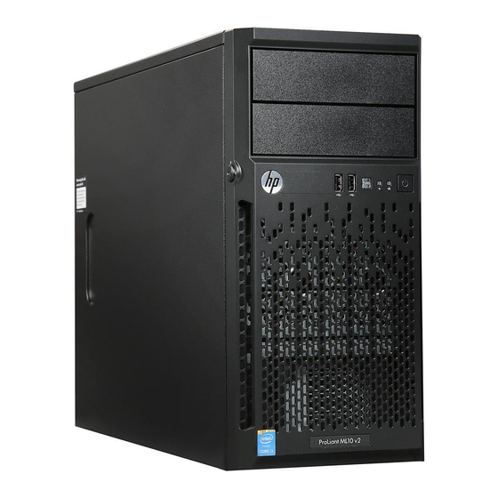
HP ProLiant ML10 v2 Server
User Guide
Abstract
This document is for the person who installs, administers, and troubleshoots servers and storage systems. HP assumes you are qualified in the
servicing of computer equipment and trained in recognizing hazards in products with hazardous energy levels.
Part Number: 811615-001
March 2015
Edition: 1
Table of Contents

Related Manuals for HP ProLiant ML10 v2


Summary of Contents for HP ProLiant ML10 v2
-
Page 1: User Guide
User Guide Abstract This document is for the person who installs, administers, and troubleshoots servers and storage systems. HP assumes you are qualified in the servicing of computer equipment and trained in recognizing hazards in products with hazardous energy levels. - Page 2 © Copyright 2015 Hewlett-Packard Development Company, L.P. The information contained herein is subject to change without notice. The only warranties for HP products and services are set forth in the express warranty statements accompanying such products and services. Nothing herein should be construed as constituting an additional warranty. HP shall not be liable for technical or editorial errors or omissions contained herein.
-
Page 3: Table Of Contents
Introduction ............................23 Drive options ............................23 Drive installation guidelines ......................23 Installing a drive ..........................23 Drive enablement option .......................... 25 Controller options ............................ 28 Installing an HP H220/H221 host bus adapter ................. 28 Optical drive option ..........................30 Contents 3... - Page 4 Software and firmware ........................49 Operating System Version Support ....................49 Version control ..........................49 HP operating systems and virtualization software support for ProLiant servers ........50 HP Technology Service Portfolio ...................... 50 Change control and proactive notification ..................50 Troubleshooting ..........................
- Page 5 Environmental specifications ........................56 Server specifications ..........................56 Power supply specifications ........................56 Support and other resources ......................57 Before you contact HP ..........................57 HP contact information ..........................57 Customer Self Repair ..........................57 Acronyms and abbreviations ......................65 Documentation feedback ......................
-
Page 6: Component Identification
Component identification Front panel components Item Description Optical drive (optional) Media drive bay Power On/Standby button and system power LED USB 2.0 connectors Drive cage bay Component identification 6... -
Page 7: Front Panel Leds And Buttons
Front panel LEDs and buttons Item Description Status UID button/LED* Solid blue = Activated Flashing blue: • 1 Hz/cycle per sec = Remote management or firmware upgrade in progress • 4 Hz/cycle per sec = iLO manual reboot sequence initiated •... -
Page 8: Rear Panel Components
3 flashes Memory 4 flashes Riser board PCIe slots 5 flashes FlexibleLOM 6 flashes Removable HP Flexible Smart Array controller/Smart SAS HBA controller 7 flashes System board PCIe slots 8 flashes Power backplane or storage backplane 9 flashes Power supply For more information, see "Front panel LEDs and buttons (on page 7)."... -
Page 9: Rear Panel Leds And Buttons
Rear panel LEDs and buttons Item Description Status NIC activity LED Solid green = Link to network Flashing green = Network active Off = No network activity NIC link LED Solid green = Link exists Off = No link exists System board components Component identification 9... -
Page 10: Dimm Slot Locations
Item Description Processor TPM connector System battery 24-pin power supply connector Mini-SAS connector SATA Port 1 SATA Port 2 Front USB connector Front I/O connector Ambient sensor connector NMI Header System maintenance switch PCIe2 x4 (1) slot 1, full-height, half-length, stand up expansion board* PCIe2 x8 (1) slot 2, full-height, half-length, stand up expansion board*... -
Page 11: Pcie Expansion Slot Definitions
To force the system to invoke the NMI handler and generate a crash dump log, do one of the following: • Use the iLO Virtual NMI feature. • Short the NMI header ("System board components" on page 9). For more information, see the HP website (http://www.hp.com/support/NMI). Component identification 11... -
Page 12: Drive Numbering
Drive numbering Component identification 12... -
Page 13: Operations
Operations Power up the server Connect each power cord to the server. Connect each power cord to the power source. Press the Power On/Standby button. The server exits standby mode and applies full power to the system. The system power LED changes from amber to green. -
Page 14: Unlock The Tower Bezel
Close and lock the tower bezel. Unlock the tower bezel The tower bezel must be unlocked and opened to access the drive cage and media bays. It must be unlocked to remove the access panel. The bezel must remain closed during normal server operations. Remove the tower bezel Unlock the tower bezel (on page 14). -
Page 15: Install The Access Panel
Pull the bezel away from the front chassis. Install the access panel Unlock the tower bezel (on page 14), if locked. Install the access panel: Place the access panel on the chassis, and slide it toward the front of the server. Tighten the thumbscrew. -
Page 16: Install The Air Baffle
CAUTION: For proper cooling, do not operate the server without the access panel, baffles, expansion slot covers, or blanks installed. If the server supports hot-plug components, minimize the amount of time the access panel is open. Power down the server (on page 13). Remove all power: Disconnect each power cord from the power source. -
Page 17: Remove The Air Baffle
Push the front end of the baffle inside the chassis. Install the access panel (on page 15). Lock the tower bezel. Power up the server (on page 13). Remove the air baffle CAUTION: For proper cooling, do not operate the server without the access panel, baffles, expansion slot covers, or blanks installed. - Page 18 Remove the air baffle. Operations 18...
-
Page 19: Setup
Setup Optional installation services Delivered by experienced, certified engineers, HP Care Pack services help you keep your servers up and running with support packages tailored specifically for HP ProLiant systems. HP Care Packs let you integrate both hardware and software support into a single package. A number of service level options are available to meet your needs. -
Page 20: Temperature Requirements
Because of the high ground-leakage currents associated with multiple servers connected to the same power source, HP recommends the use of a PDU that is either permanently wired to the building’s branch circuit or includes a nondetachable cord that is wired to an industrial-style plug. NEMA locking-style plugs or those complying with IEC 60309 are considered suitable for this purpose. -
Page 21: Server Warnings And Cautions
Get help to lift and stabilize the product during installation or removal, especially when the • product is not fastened to the rails. HP recommends that a minimum of two people are required for all rack server installations. A third person may be required to help align the server if the server is installed higher than chest level. -
Page 22: Installing The Operating System
During the initial boot, to modify the server configuration ROM default settings, press F9 when prompted from the start up sequence to enter the RBSU. By default, RBSU runs in the English language. For more information on automatic configuration, see the HP ROM-Based Setup Utility User Guide in the HP RBSU Information Library (http://www.hp.com/go/rbsu/docs). -
Page 23: Hardware Options Installation
The server supports up to four non-hot-plug LFF drives in the default configuration, or up to six LFF drives if two SATA drive enablement kits are installed. The embedded storage controller supports SATA drive installation only. For SAS drive installation, install an HP host bus adapter. Drive installation guidelines When adding drives to the server, observe the following general guidelines: •... - Page 24 Remove the air baffle (on page 17). Disconnect the existing cables from the drive. Remove the installed drive cage assembly. Use the screws on the drive cage to install the drive. Install the drive into the drive cage. Hardware options installation 24...
-
Page 25: Drive Enablement Option
Install the drive cage into the chassis. Connect all drive cables. Install the air baffle (on page 16). Install the access panel (on page 15). Install the tower bezel (on page 13). Connect each power cord to the server. Connect each power cord to the power source. Power up the server (on page 13). - Page 26 Remove all power: Disconnect each power cord from the power source. Disconnect each power cord from the server. Do the following: Unlock the tower bezel (on page 14). Remove the tower bezel (on page 14). Place the server on its side. Remove the access panel (on page 15).
- Page 27 Secure the M3 screws (black) to the drive carrier. Insert the drive carrier into the media bay until the carrier locks into place. Connect the drive cables. Connect and secure the SATA cable. Hardware options installation 27...
-
Page 28: Controller Options
RAID configuration, first download SPP (http://www.hp.com/go/spp/download). For SAS drive installation, install an HP H220/H221 host bus adapter. For more information about the controller and its features, see the HP Dynamic Smart Array RAID Controller User Guide on the HP website (http://www.hp.com/support/DSA_RAID_UG_en). - Page 29 Disconnect each power cord from the server. Unlock the tower bezel (on page 14). Remove the access panel (on page 15). Remove the air baffle (on page 17). Remove the expansion slot cover retainer. Remove the slot cover blank. Disconnect the Mini-SAS cable from the system board. Connect the mini-SAS cable to the host bus adapter.
-
Page 30: Optical Drive Option
Close the expansion slot cover retainer. Install the air baffle (on page 16). Install the access panel (on page 15). Return the server to an upright position. Connect each power cord to the server. Connect each power cord to the power source. Power up the server (on page 13). - Page 31 Remove the media bay blank. Remove the EMI shield. Attach four screws from the chassis to the optical drive. Hardware options installation 31...
- Page 32 Install the optical drive into the media drive bay ("Optical drive cabling" on page 42). Connect the drive cables: Connect the power cable to the drive. Connect one end of the SATA cable to the drive and the other end to the system board. For cable routing information, see "Optical drive cabling (on page 42)."...
-
Page 33: Memory Options
Certain performance features are unique with HP SmartMemory. The industry supports UDIMM at 2 DIMMs per channel at 1066 MT/s. HP SmartMemory supports 2 DIMMs per channel at 1600 MT/s, or 25% greater bandwidth. DIMM identification To determine DIMM characteristics, use the label attached to the DIMM and the following illustration and table. -
Page 34: Single-Rank And Dual-Rank Dimms
L = LRDIMM (load reduced) For the latest supported memory information, see the QuickSpecs on the HP website (http://www.hp.com/go/qs). At the website, choose the geographic region, and then locate the product by name or product category. Single-rank and dual-rank DIMMs DIMM configuration requirements are based on these classifications: •... -
Page 35: General Dimm Slot Population Guidelines
Non-ECC UDIMMs • When installing DIMMs: Populate the DIMM slots in this sequence: 2-A, 4-B, 1-C, 3-D. Use HP-qualified UDIMMs. Installing a DIMM Power down the server (on page 13). Remove all power: Disconnect each power cord from the power source. -
Page 36: Setting Up The Hp Ps1810-24G Switch (Optional)
After installing the DIMMs, to configure memory protection mode, use RBSU. Setting up the HP PS1810-24G Switch (optional) If you intend to use the server with the companion HP PS 1810-24G Switch, follow the procedures in this section. For more information on switch-related settings and operational procedures, see the documentation for your switch model on the HP website (http://www.hp.com/networking/support). -
Page 37: Hp Trusted Platform Module Option
HP Trusted Platform Module option For more information about product features, specifications, options, configurations, and compatibility, see the product QuickSpecs on the HP website (http://www.hp.com/go/qs). Use these instructions to install and enable a TPM on a supported server. This procedure includes three sections: Installing the Trusted Platform Module board. -
Page 38: Installing The Trusted Platform Module Board
Recovery Mode after BitLocker detects a possible compromise of system integrity. • HP is not liable for blocked data access caused by improper TPM use. For operating instructions, see the encryption technology feature documentation provided by the operating system. - Page 39 CAUTION: Any attempt to remove an installed TPM from the system board breaks or disfigures the TPM security rivet. Upon locating a broken or disfigured rivet on an installed TPM, administrators should consider the system compromised and take appropriate measures to ensure the integrity of the system data.
-
Page 40: Retaining The Recovery Key/Password
OS application TPM settings. For more information on firmware updates and hardware procedures, see the HP Trusted Platform Module Best Practices White Paper on the HP website (http://www.hp.com/support). -
Page 41: Cabling
Cabling overview This section provides guidelines to help make informed decisions about cabling the server and hardware options to optimize performance. For information on cabling peripheral components, see the white paper on high-density deployment at the HP website (http://www.hp.com/products/servers/platforms). CAUTION: When routing cables, always be sure that the cables are not in a position where they can be pinched or crimped. -
Page 42: Drive To Controller (Sata And Sas Drive Support)
Drive to controller (SATA and SAS drive support) Item Description Drive power cable Mini-SAS cable Optical drive cabling Item Description Optical drive power cable SATA cable Cabling 42... -
Page 43: Software And Configuration Utilities
QuickSpecs on the HP website (http://www.hp.com/go/qs). HP iLO The iLO subsystem is a standard component of HP ProLiant servers that simplifies initial server setup, server health monitoring, power and thermal optimization, and remote server administration. The iLO subsystem includes an intelligent microprocessor, and secure memory. -
Page 44: Integrated Management Log
Control iLO by using a remote management tool. For more information about iLO features, see the iLO documentation on the HP website (http://www.hp.com/go/ilo/docs). For a complete list of supported features and functionality, see the HP iLO 4 QuickSpecs on the HP website (http://h18000.www1.hp.com/products/quickspecs/14276_div/14276_div.pdf). Integrated Management Log The IML records hundreds of events and stores them in an easy-to-view form. -
Page 45: Hp Insight Diagnostics
HP BladeSystem c-Class enclosures, you can register a server or enclosure to communicate directly to HP Insight Online without the need to set up an HP Insight Remote Support centralized Hosting Device in your local environment. HP Insight Online will be your primary interface for remote support information. -
Page 46: Scripting Toolkit For Windows And Linux
SPP is a comprehensive systems software (drivers and firmware) solution delivered as a single package with major server releases. This solution uses HP SUM as the deployment tool and is tested on all supported HP ProLiant servers including HP ProLiant Gen8 and later servers. -
Page 47: Utilities And Features
Gen8 servers, HP SSA replaces ACU with an enhanced GUI and additional configuration features. HP SSA exists in three interface formats: the HP SSA GUI, the HP SSA CLI, and HP SSA Scripting. Although all formats provide support for configuration tasks, some of the advanced tasks are available in only one format. -
Page 48: Usb Support
ASR increases server availability by restarting the server within a specified time after a system hang. At the same time, the HP SIM console notifies you by sending a message to a designated pager number that ASR has restarted the system. You can disable ASR from the System Management Homepage or through RBSU. -
Page 49: Drivers
SPP, see the HP website (http://www.hp.com/go/spp/download). To locate the drivers for a particular server, go to the HP website (http://www.hp.com/go/hpsc) and click on Drivers, Software & Firmware. Then, enter your product name in the Find an HP product field and click Software and firmware Software and firmware should be updated before using the server for the first time, unless any installed software or components require an older version. -
Page 50: Hp Operating Systems And Virtualization Software Support For Proliant Servers
(http://www.hp.com/go/ossupport). HP Technology Service Portfolio Connect to HP for assistance on the journey to the new style of IT. HP Technology Services delivers confidence and reduces risk to help you realize agility and stability in your IT infrastructure. Utilize our consulting expertise in the areas of private or hybrid cloud computing, big data and mobility requirements, improving data center infrastructure and better use of today’s server, storage and networking... -
Page 51: Troubleshooting
• Simplified Chinese (http://www.hp.com/support/ProLiant_TSG_v1_sc) The HP ProLiant Gen8 Troubleshooting Guide, Volume II: Error Messages provides a list of error messages and information to assist with interpreting and resolving error messages on ProLiant servers and server blades. To view the guide, select a language: •... -
Page 52: System Battery Replacement
System battery replacement If the server no longer automatically displays the correct date and time, then replace the battery that provides power to the real-time clock. Under normal use, battery life is 5 to 10 years. WARNING: The computer contains an internal lithium manganese dioxide, a vanadium pentoxide, or an alkaline battery pack. - Page 53 IMPORTANT: Replacing the system board battery resets the system ROM to its default configuration. After replacing the battery, reconfigure the system through RBSU. To replace the component, reverse the removal procedure. For more information about battery replacement or proper disposal, contact an authorized reseller or an authorized service provider.
-
Page 54: Regulatory Information
Regulatory information Safety and regulatory compliance For safety, environmental, and regulatory information, see Safety and Compliance Information for Server, Storage, Power, Networking, and Rack Products, available at the HP website (http://www.hp.com/support/Safety-Compliance-EnterpriseProducts). Turkey RoHS material content declaration Ukraine RoHS material content declaration Warranty information HP ProLiant and X86 Servers and Options (http://www.hp.com/support/ProLiantServers-Warranties) -
Page 55: Electrostatic Discharge
Electrostatic discharge Preventing electrostatic discharge To prevent damaging the system, be aware of the precautions you need to follow when setting up the system or handling parts. A discharge of static electricity from a finger or other conductor may damage system boards or other static-sensitive devices. -
Page 56: Specifications
Depending on installed options, the server is configured with one of the following power supplies: • HP 350 W 4U Integrated Power Supply For more information about the power supply features, specifications, and compatibility, see the HP website (http://www.hp.com/go/proliant/powersupply). Specifications 56... -
Page 57: Support And Other Resources
If during the diagnosis period HP (or HP service providers or service partners) identifies that the repair can be accomplished by the use of a CSR part, HP will ship that part directly to you for replacement. There are two categories of CSR parts: •... - Page 58 HP specifies in the materials shipped with a replacement CSR part whether a defective part must be returned to HP. In cases where it is required to return the defective part to HP, you must ship the defective part back to HP within a defined period of time, normally five (5) business days. The defective part must be returned with the associated documentation in the provided shipping material.
- Page 59 HP sono realizzati con numerosi componenti che possono essere riparati direttamente dal cliente (CSR, Customer Self Repair). Se in fase di diagnostica HP (o un centro di servizi o di assistenza HP) identifica il guasto come riparabile mediante un ricambio CSR, HP lo spedirà direttamente al cliente per la sostituzione.
- Page 60 HP podrá cobrarle por el de sustitución. En el caso de todas sustituciones que lleve a cabo el cliente, HP se hará cargo de todos los gastos de envío y devolución de componentes y escogerá la empresa de transporte que se utilice para dicho servicio.
- Page 61 HP. Informatie over Service Partners vindt u op de HP website (http://www.hp.com/go/selfrepair). Reparo feito pelo cliente Os produtos da HP são projetados com muitas peças para reparo feito pelo cliente (CSR) de modo a minimizar o tempo de reparo e permitir maior flexibilidade na substituição de peças com defeito. Se, durante o período de diagnóstico, a HP (ou fornecedores/parceiros de serviço da HP) concluir que o reparo...
- Page 62 Opcional – Peças cujo reparo feito pelo cliente é opcional. Essas peças também são projetadas para o reparo feito pelo cliente. No entanto, se desejar que a HP as substitua, pode haver ou não a cobrança de taxa adicional, dependendo do tipo de serviço de garantia destinado ao produto.
- Page 63 Support and other resources 63...
- Page 64 Support and other resources 64...
-
Page 65: Acronyms And Abbreviations
Advanced Memory Protection Automatic Server Recovery BSMI Bureau of Standards, Metrology and Inspection Conformité Européenne (European Conformity) Canadian Standards Association Customer Self Repair electromagnetic interference FBWC flash-backed write cache Federal Communications Commission HP SIM HP Systems Insight Manager Acronyms and abbreviations 65... - Page 66 HP SUM HP Smart Update Manager International Electrotechnical Commission Integrated Lights-Out Integrated Management Log International Organization for Standardization large form factor LRDIMM load reduced dual in-line memory module nonmaskable interrupt NVRAM nonvolatile memory PCIe Peripheral Component Interconnect Express power distribution unit...
- Page 67 Rapid Deployment Pack radio frequency radio frequency interference serial attached SCSI SATA serial ATA Secure Digital HP Service Pack for ProLiant TMRA recommended ambient operating temperature Trusted Platform Module UDIMM unregistered dual in-line memory module unit identification universal serial bus...
- Page 68 xHCI Extensible Host Controller Interface Acronyms and abbreviations 68...
-
Page 69: Documentation Feedback
Documentation feedback HP is committed to providing documentation that meets your needs. To help us improve the documentation, send any errors, suggestions, or comments to Documentation Feedback (mailto:[email protected]). Include the document title and part number, version number, or the URL when submitting your feedback. -
Page 70: Index
Hot-plug SAS/SATA hard drive cabling 41 controller 28 HP Insight Diagnostics 45 CSR (customer self repair) 57 HP Insight Remote Support software 44, 50 customer self repair (CSR) 57 HP Smart Update Manager overview 46 HP technical support 50, 57... - Page 71 installing the access panel 15 rear panel LEDs 9 Integrated Lights-Out (iLO) 44 recovering a lost password 40 Integrated Management Log (IML) 44 redundant ROM 48 registering the server 22 regulatory compliance notices 54 removing the access panel 15 Japanese notice 54 replacing the batteries 52 retaining the recovery key/password 40 ROM redundancy 48...
- Page 72 ROM 48 USB support 48 utilities 43, 47 utilities, deployment 46 ventilation 19 Virtualization option 50 warnings 21 website, HP 57 Index 72...