beautypg.com
Manuals
Brands
YASKAWA Manuals
Controller
MP2300S
YASKAWA MP2300S Manuals
Manuals and User Guides for YASKAWA MP2300S. We have
4
YASKAWA MP2300S manuals available for free PDF download: User Manual, Manual
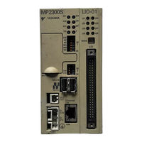
YASKAWA MP2300S User Manual (461 pages)
Machine Controller
Brand:
YASKAWA
| Category:
Controller
| Size: 19.24 MB
Table of Contents
Basic Terms
3
Manual Configuration
3
Using this Manual
3
Indication of Reverse Signals
3
Terms Used to Describe “Torque”
5
Safety Information
6
Safety Precautions
7
Safe Installation
8
Safe Storage and Transportation
8
Selecting, Separating, and Laying External Cables
9
Wiring
9
Maintenance and Inspection Precautions
10
Disposal Precautions
10
General Precautions
10
Contents
13
Table of Contents
17
Overview
17
MP2300S Features
18
Basic Module Appearance
19
MP2300S Configuration
19
MP2300S Modules
20
System Configuration
21
Example
21
Example of Distributed Synchronizing System
22
Mechatrolink Compatible Devices
23
MECHATROLINK-I/II Compatible Devices
23
Servopacks and Inverters
23
Mechatrolink-III Compatible Devices
24
Cables and Accessories
25
Accessories and Options
26
Software (Programming Tool)
26
Specifications and Functions
27
General Specifications
28
Product Specifications
29
Function Lists
30
PLC Function Specifications
30
Motion Control Function Specifications
31
Basic Module
33
Outline of Functions
33
Basic Module External Appearance
34
Basic Module Indicators
34
External Appearance, LED Indicators, and Switch Settings
34
Switch Settings
35
Hardware Specifications
37
218IFA Module (Ethernet)
38
Specification of 218IFA Module
39
Module Configuration Definition
41
218IFA Module Detailed Screen
42
Transmission Parameter Setting Items
44
Detailed Setting Screen of Transmission Parameter Setting
45
Message Communication Item of Connection Parameter Setting
46
Simple Setting Screen for Message Communication
48
Automatic Receive Setting Screen for Message Communication
49
I/O Message Communication Item Connection Parameter Setting
51
Easy Setting Window for I/O Message Communication
53
Transmission Parameter Item
55
Message Communication and I/O Message Communication Items
55
Built-In SVB Module
57
Synchronization between Modules
59
Timing at Which Modules Are Synchronized
60
Operation When High-Speed Scan Cycle Is Changed
60
Operation When the Mechatrolink Communication Cycle Is Changed
60
Conditions When the Power Supply Must be Turned off and on
60
SVB Modules Specifications
61
Mechatrolink Communication Specifications
63
Maximum Number of Slave Stations
63
Transmission Distance and Maximum No. of Slave Stations
64
SVB Module Configuration
64
Mechatrolink Transmission Definition
66
Transmission Bytes, Communication Cycle, Number of Retries to Slaves
68
Communication Cycle that Can be Set
69
Link Assignment Tab Page
70
Deleting a Station Assignment
70
I/O Map Tab
71
Sts
71
SVB Definition
72
Opening the SVB Definition Window
72
Precautions When Saving the Servo User Constant
73
SVR Virtual Motion Module
74
Example SVR Usage
75
System Configuration Example
75
SVR Operation
76
SVR Execution Timing
76
Differences from SVB Simulation Mode
76
Processing Time
76
M-EXECUTOR Module (Motion Program Executor)
77
M-Executor Module Specification
78
I/O Register Details
80
Detailed Screen
81
Control Register Mapping Window
83
Program Execution Registration Screen (M-Executor Screen)
85
Execution Scheduling
86
Option Module Overview List
88
External Appearance of the Basic Module
90
Basic Module with Metal Fittings
91
Mounting and Wiring
92
DIN Rail Mounting
93
Mounting MP2300S
93
Method
93
Screwed Method of Mounting
96
MP2300S Mount Direction
98
Space Required for Mounting MP2300S
99
Replacing and Adding Optional Modules
100
Removing Optional Modules
100
Installing Optional Modules
102
Basic Module Connections
103
Connectors Diagram
103
Power Supply Connector
104
Mechatrolink Connectors
105
Cable Connections between the Unit and I/O Units and Servo-Packs
107
Cable Connections between the Unit and SGD-Vopacks
108
Connection Example between the Unit, SERVOPACK, and IO2310
109
Ethernet Connector Details
110
Ethernet Connection Example
111
RLY out Connector Details
114
RLY out Connection Example
115
System Connection Example
116
System Start up and Easy Programming
117
System Startup Overview
118
System Startup Preparation
119
Preparation (Step 1)
119
Wiring
119
Self Configuration
121
Test Operation
122
Starting and Connecting MPE720 Ver.6
122
Operating Manually in the Test Operation Screen
122
Axis Selection and Servo on
123
Jog Operation
124
Programming Procedure
125
Programming (Step 2)
125
Editing Motion Program
126
Registering Program Execution
127
Executing Motion (Step 3)
127
Starting a Motion Program Using the Operation Control Panel
128
Required Equipment
129
Starting Motion Program from an External Signal
129
Overview
129
Mapping of the Touch Panel Manufactured by Digital Electronics Corp
130
Creation Procedure
131
Creating a Sequence Program
131
Outline of Motion Control Systems
134
Startup Sequence and Basic Operation
135
DIP Switch Settings
135
Startup Sequence
136
Startup Sequence Operation Details
137
Self-Diagnosis at Startup
137
Self-Configuration
137
Online Self-Diagnosis
137
User Programs
138
Types and Execution Timing of User Program
138
Motion Programs
139
Groups
139
How to Run a Motion Program
142
How to Designate a Motion Program
144
Work Register
146
Status Flag of a Motion Program
147
Control Signal
148
Timing Chart for Motion Program Control Signals
149
Interpolation Override
149
System Work Number
150
How to Operate a Work Register
151
A Way to Immediately Control a Motion Program from External Equipment
152
A Way to Control a Motion Program Via a Sequence or Ladder Program
153
Example Using a Sequence Program
153
Example Using a Ladder Program
154
Monitor the Motion Program Execution Information Using S Register
157
Register Areas for Motion Program Execution Information
158
Details of Program Information Used by Work N
159
Sequence Program
160
How to Designate a Sequence Program
161
Sequence Program Alarm
162
Ladder Drawings (DWG)
163
Execution Control of Drawings
164
Hierarchical Structure of Drawings
165
Drawing Execution Processing Method
166
Standard System Functions
167
User Functions
167
Types of Registers
168
DWG Registers
168
Function Registers
169
Register Ranges in Programs
170
Data Types
171
How to Use Subscripts I, J
172
Bit Type Attached with a Subscript
172
Integer Type Attached with a Subscript
172
Long Integer or Real Type Attached with a Subscript
172
Register Designation
173
Self-Configuration
174
How to Execute Self-Configuration
175
Procedure Using the DIP Switch
175
INIT Switch and RAM Data
176
Turning off Power after Executing Self-Configuration
176
Procedure Using the Unit
177
Self-Configuration for All the Modules
177
Self Configuration of each Module
180
Definition Information Updated with Self-Configuration
183
Definition Data of the Unit's Basic Module
183
SVB Module Definitions
184
SVR Definition
185
M-EXECUTOR Definition
185
Precautions When User Definition File Is Configured/Changed
186
Precaution on Using MP2300S
186
Setting or Changing Module Configuration Definition Files
187
Setting and Changing the Scan Time
188
Scan Time Set Value Examples
189
Built-In Ethernet Communications
190
Communication Methods
191
Communication with Other MP Series
192
When the Unit Acts as Slave (Automatic Receive Function Is Used)
192
How to Set up the Unit's Side
194
How to Set up in the Message Communication Easy Setting Window
195
How to Set up the Remote Device (MP2300) to be Connected
198
Message Transmit Function (MSG-SND)
200
Input/Output Definitions for Message Transmit Functions
201
Parameter List Setting Example for the Message Transmit Function
202
Example of Using the Message Transmit Function in a Ladder Program
203
How to Start Communications
205
When the MP2300S Acts as Slave (Ladder Program Which Uses a MSG-RCV Function)
206
How to Set up Transmission Parameters
208
Message Receive Function (MSG-RCV)
211
Input/Output Definition Contents for Message Receive Functions
212
Parameter List Setting Example for Message Receive Function
213
Example of Using the Message Receive Function in a Ladder Program
214
Input/Output Definitions Contents for Message Transmit Functions
220
Parameter List Setting for the Message Transmit Function
221
When the MP2300S Acts as Master (I/O Message Communication Function Is Used)
225
How to Set up in the I/O Message Communication Easy Setting Window
228
Data Update Timing
229
When the MP2300S Acts as Master (Ladder Program Which Uses a MSG-SND Function)
238
Input/Output Definition Contents for Message Transmit Functions
244
How to Set up the Remote Equipment (MP2300) to be Connected
249
Procedure to Set up in the CP-218 Connection Parameter Window
250
Input/Output Definitions Contents for Message Receive Functions
252
How to Start Communication
253
Communication with Touch Panel
254
When the MP2300S Acts as Slave (Automatic Receive Function Is Used)
254
How to Set up a Touch Panel
259
Port Number
260
Screen Creation Example
262
Relationship between GP-Pro EX Address Display and MP2300S Register
262
To Start Communication
263
Communication with PLC Manufactured by Mitsubishi Electric Corporation (MELSEC Protocol)
264
When the MP2300S Acts as Slave (Automatic Receive Function Is Used)
264
How to Set up the Remote Device (MELSEC Q Series) to be Connected
270
Procedure Overview to Communicate Using a Ladder Program
271
When the MP2300S Acts as Master (I/O Message Communication Function Is Used)
272
How to Set up the Remote Equipment (MELSEC Q Series) to be Connected
277
Slave CPU Synchronous Function
279
Function
280
Requirements to Execute Slave CPU Synchronous Function
281
Requirements and Setting of Execution
281
Supported Version
281
How to Set up Slave CPU Synchronous Function
282
Slave Side Setting
283
How to Execute Slave CPU Synchronous Function
285
Turning on the Master Side Power First
285
Turning on the Slave Side Power First
286
Operation
287
Input/Output Register
287
Master Side Input/Output Data
287
Input Data Details
287
Slave Status Details
288
Output Data Details
288
Slave Side Input/Output Data
289
Control Bit Details
290
Input/Output Data Flow between Master and Slave
291
From MP2000 (Master) to the Unit (Slave)
291
From the Unit (Slave) to MP2000 (Master)
292
How to Determine Slave CPU Synchronous State
293
How to Check with a Master Side Application
293
How to Check with a Slave Side Application
293
Calculation of Slave CPU Synchronous Delay Time
294
How to Use Scan Counter
295
Checking the Master Status Using a Slave Side Application
295
Checking a Slave Status Using a Master Side Application
295
How to Determine an Input Error Using an Application Program
296
How to Recover from Input Error
301
Management to Resume Slave CPU Synchronization
302
Precautions on Usage
306
Effect of Error on Slave CPU Synchronous Operation
307
Maintenance and Inspection
308
Daily Inspections
309
Regular Inspections
310
Replacing the Basic Module Battery
311
Troubleshooting
312
Basic Flow of Troubleshooting
313
LED Indicator Meanings
314
Problem Classification
315
Overview
315
MP2300S Error Check Flowchart
316
Troubleshooting Details
317
Operation Errors
317
Troubleshooting Procedure Examples
318
I/O Errors
320
Watchdog Timer Timeout Errors
321
Module Synchronization Errors (Ver. 2.75 or Later)
321
System Errors
322
System Service Registers
325
Shared by All Drawings
325
DWG.H Only
325
A System Registers Lists
325
DWG.L Only
326
Scan Execution Status and Calendar
327
Program Software Numbers and Remaining Program Memory Capacity
327
System Status
328
System Error Status
329
User Operation Error Status
331
User Operation Error Codes 1
331
System Service Execution Status
332
User Operation Error Codes 2
332
Data Trace Execution Status
332
Latest Data Trace Record Numbers
332
User Operation Error Status Details
333
System I/O Error Status
334
Compact Flash Card-Related System Registers
335
Interrupt Status List
336
Details on Interrupting Module
336
Module Information
337
MPU-01 System Status
338
Motion Program Information
339
System Work Number 1 to 8
339
System Word Number 9 to 16
340
Operations and Parameter Data Flow
342
Normal Operation
343
When the Servopack Tab Page Is Open
343
Servopack Parameters Saved in the MPE720
344
Copying Current Values to Set Values (Input Data) in the Servopack Tab
346
Changing Parameters in the Servopack Tab Page
348
Saving Data to Flash Memory
350
Precautions When Saving Servopack Parameters
350
C Initializing Servopacks
351
D Initializing the Absolute Encoder
352
Σ-V Servopack
352
Σ-III Servopack
353
Σ-II Servopack
354
Σ-I Servopack
356
Fixed Parameter List
358
E Motion Parameter Details
358
Setting Parameter List
360
Monitoring Parameter List
365
F Simple Connection Function of the Engineering Tool
369
Preparation
369
Procedure
369
Difference between Ethernet (LP) and Ethernet
371
When There Are Multiple LAN Ports on the Personal Computer
371
Controller Search Function
371
Specification Overview of the Message Transmit Function
373
G MSG-SND/MSG-RCV Functions (Ethernet
373
Message Transmit Function (MSG-SND
373
I/O Item Details of the Message Transmit Function
374
Output Item
376
Message Transmit Function Parameter List (Param) Overview
378
Memobus Paremater List
378
Non-Procedual Parameter List
378
Function Setting and Parameter Details for MEMOBUS and Extended MEMOBUS Protocols
378
Function Setting and Parameter Details for MELSEC Protocol
378
Function Setting and Parameter Details for MODBUS/TCP Protocol
378
Function Setting and Parameter Details for Non-Procedural Protocol
378
Function Setting/Parameter Details for Memobus Protocols
379
Message Transmit Function Setting
379
Process Result (PARAM00)
380
Status (PARAM00)
381
Request
381
Result
381
Command
381
Parameter
382
Connection Number (PARAM02)
383
Option (PARAM03)
383
Function Code (PARAM04)
384
Data Address (PARAM05)
385
Data Size (PARAM06)
386
Remote CPU Number (PARAM07)
387
Offset (PARAM08 to PARAM11)
387
Reserved by System 1 (PARAM12)
388
Reserved by System 2 (PARAM13 to PARAM16)
388
Function Setting and Parameter Details for MELSEC Protocol
389
Reserved by System 2 (PARAM13-PARAM16)
393
Function Setting and Parameter Details for MODBUS/TCP Protocol
394
Function Setting and Parameter Details for Non-Procedural Protocol
399
Status (PARAM01)
401
Register Offset (PARAM11)
403
Data Flow When Reading
404
Relationship between Data Address, Data Size, and Offset for MSG-SND Function
404
Data Flow When Writing
405
Parameter Setting
405
Parameter List Setting
406
Reading Example of Coil State
407
Specification Overview of the Message Receive Function
408
Message Receive Function (MSG-RCV
408
I/O Item Details of the Message Receive Function
409
Message Receive Function Parameter List (Param) Overview
413
Memobus Parameter List
414
Non-Procedural Parameter List
414
Message Receive Function Setting
415
Function Setting and Parameter Details for MEMOBUS and Extended MEMOBUS Protocols
415
Write Range (PARAM12, PARAM13)
422
Reserved by System 1 (PARAM14)
422
Reserved by System 2 (PARAM15, PARAM16)
422
Function Setting and Parameter Details for MELSEC Protocol
423
Function Setting and Parameter Details for MODBUS/TCP Protocol
427
Function Setting and Parameter Details for Non-Procedural Protocol
431
Register Offset (PARAM12)
434
Write Range HI (PARAM13)
435
Relationship Btw Data Address, Data Size, Offset for MSG-RCV Function
436
Writing Example to Multiple Holding Registers
439
Communication Buffer Channel
440
Clearing D Registers at Startup
442
Supported Versions
442
Setting Procedure for Clearing D Registers at Startup
442
H Optional Functions
442
Security
443
Target Data
443
Security Identification
443
Precautions for Transfers
443
Opening the Security Setting Dialog Box
444
New Security Settings
445
Changing the Restriction Privilege
446
Changing the File Reading Restriction
447
Changing the Security Key
447
Releasing Security
448
Security Operation
449
Privilege Settings in User Applications
449
File Reading with Security Settings
449
Initialization
449
Security-Related System Registers
450
Application Precautions
450
Battery Backup for Table Data
451
Battery Backup Memory Capacity
451
System Registers for Battery Backup Memory Capacity
451
Setting Procedure for Using Battery Backup Memory
452
Precautions When Using Battery Backup for Table Data
454
Installing MPE720 Version 6
455
Index
456
Revision History
459
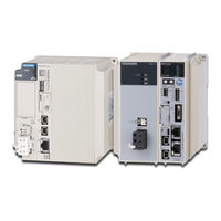
YASKAWA MP2300S User Manual (462 pages)
Machine Controller, Basic Module
Brand:
YASKAWA
| Category:
Controller
| Size: 14.76 MB
Table of Contents
1 Overview
15
Table of Contents
15
MP2300S Features
16
MP2300S Configuration
17
Basic Module Appearance
17
MP2300S Modules
18
System Configuration
19
Example
19
Example of Distributed Synchronizing System
20
MECHATROLINK-Compatible Devices
21
Servopacks
21
Modules
21
Cables and Accessories
22
Cables
22
Accessories and Options
23
Software (Programming Tool)
23
2 Specifications and Functions
25
Specifications
26
General Specifications
26
Product Specifications
27
Function Lists
28
Basic Module
31
Outline of Functions
31
External Appearance, LED Indicators, and Switch Settings
32
Specifications
35
218IFA Module (Ethernet)
36
Built-In SVB Module
54
SVR Virtual Motion Module
71
M-EXECUTOR Module (Motion Program Executor)
74
Option Module
85
Option Module Overview List
85
Machine Controller MP2000 Series SVB/SVB
85
External Appearance
87
Basic Module
87
Basic Module with Metal Fittings
88
3 Mounting and Wiring
89
Mounting MP2300S
90
Method
90
MP2300S Mount Direction
95
Space Required for Mounting MP2300S
96
Replacing and Adding Optional Modules
97
Basic Module Connections
100
Connectors
100
Power Supply Connector
101
MECHATROLINK Connectors
102
Ethernet Connector Details
107
RLY out Connector Details
111
System Connection Example
113
4 System Start up and Easy Programming
115
Overview - - - - - - - - - - - - - - - - - - - - - - - - - - - - - - - - - - - - - - - - - - - - - - - - -
115
System Startup Overview
116
Preparation (Step 1)
117
Wiring
117
Self Configuration
119
Test Operation
120
Programming (Step 2)
123
Programming Procedure
123
Executing Motion (Step 3)
125
Registering Program Execution
125
Starting a Motion Program Using the Operation Control Panel
126
Starting Motion Program from an External Signal
127
Overview
127
Required Equipment
127
Creation Procedure
129
5 Outline of Motion Control Systems
133
Startup Sequence and Basic Operation
134
DIP Switch Settings
134
Startup Sequence
135
Startup Sequence Operation Details
136
LED Indicator Details
137
User Programs
138
Types and Execution Timing of User Program
138
Motion Programs
139
Sequence Program
160
Ladder Drawings (DWG)
163
Registers
168
Types of Registers
168
Data Types
171
How to Use Subscripts I, J
172
Register Designation
173
Self-Configuration
174
How to Execute Self-Configuration
175
Definition Information Updated with Self-Configuration
183
Precaution on Using MP2300S
186
Precautions When User Definition File Is Configured/Changed
186
Setting or Changing Module Configuration Definition Files
187
Setting and Changing the Scan Time
188
6 Ethernet Communications
191
Communication Methods
192
Communication with Other MP Series
193
When the MP2300S Acts as Slave (Automatic Receive Function Is Used)
193
Param no
201
When the MP2300S Acts as a Slave (Ladder Program Which Uses a MSG-RCV Function)
207
OUT Process Result
214
OUT Status
214
IN Connection Number
214
IN Option
222
IN Function Code
222
IN Remote CPU Number
222
When MP2300S Acts as Master (I/O Message Communication Function Is Used)
226
IN Coil Offset
235
IN Input Relay Offset
235
IN Input Register Offset
235
When the MP2300S Acts as Master (Ladder Program Which Uses MSG-SND Function)
239
IN Holding Register Offset
246
Communication with Touch Panel
255
When MP2300S Acts as Slave
255
Communication with PLC Manufactured by Mitsubishi Electric Corporation (MELSEC Protocol)
265
When the MP2300S Acts as Slave (Automatic Receive Function Is Used)
265
When the MP2300S Acts as Master (I/O Message Communication Function Is Used)
273
7 Slave CPU Synchronous Function
281
Overview - - - - - - - - - - - - - - - - - - - - - - - - - - - - - - - - - - - - - - - - - - - - - - - - - - - - - - - - - - -
281
Function
282
Overview
282
Requirements and Setting of Execution
283
Supported Version
283
Requirements to Execute Slave CPU Synchronous Function
283
How to Set up Slave CPU Synchronous Function
284
How to Execute Slave CPU Synchronous Function
287
Operation
289
Input/Output Register
289
How to Determine Slave CPU Synchronous State
295
Calculation of Slave CPU Synchronous Delay Time
296
How to Use Scan Counter
297
How to Determine Input Error
298
Management to Resume Slave CPU Synchronization
304
Precautions
308
Precautions on Usage
308
Effect of Error on Slave CPU Synchronous Operation
309
8 Maintenance, Inspection, and Troubleshooting
311
Inspection Items
312
Daily Inspections
312
Regular Inspections
313
Replacing the Basic Module Battery
314
Troubleshooting
315
Basic Flow of Troubleshooting
315
MP2300S Error Check Flowchart
316
LED Indicators
316
Troubleshooting System Errors
321
Motion Program Alarms
335
List of Causes for Command Error Completed Status
340
Troubleshooting Motion Errors
343
Appendices
355
Appendix A System Registers Lists
355
A.1 System Service Registers - - - - - - - - - - - - - - - - - - - - - - - - - - - - - - - - - - - - - - - - - - - - - - - - -
355
A System Registers Lists
356
System Service Registers
356
Scan Execution Status and Calendar
358
Program Software Numbers and Remaining Program Memory Capacity
358
B SERVOPACK Parameter Data Flow
359
Operations and Parameter Data Flow
359
C Initializing Servopacks
368
D Initializing the Absolute Encoder
369
E Motion Parameter Details
374
Fixed Parameter List
374
Setting Parameter List
376
Monitoring Parameter List
381
F How to Set up Communication Process
385
Preparation
385
Procedure
385
G MSG-SND/ MSG-RCV Functions
390
Message Transmit Function (MSG-SND
390
G.1.3 Message Transmit Function Parameter List (Param) Overview
394
Note: IN: Input, OUT: Output, SYS: for System Use
394
Send_Ok
397
Rec_Ok
397
Abort_Ok
397
Fmt_Ng
397
Seq_Ng
397
SYS Reserved
394
To 16 SYS Reserved
394
Code (Hex) Abbreviation U_SEND U_REC ABORT
417
Message Receive Function (MSG-RCV
429
Communication Buffer Channel
456
YASKAWA MP2300S Manual (108 pages)
MP2000/MP3000 Series MP/INVERTER/SERVO Ethernet Driver
Brand:
YASKAWA
| Category:
Network Hardware
| Size: 4.43 MB
Table of Contents
Table of Contents
1
System Configuration
3
External Device Selection
12
Communication Settings
13
Setup Items
80
Supported Devices
86
Device Code and Address Code
104
Error Messages
105
YASKAWA MP2300S Manual (24 pages)
Machine Controller
Brand:
YASKAWA
| Category:
Controller
| Size: 0.75 MB
Table of Contents
Related Manuals
3
General Precautions
3
Safety Information
4
Notes for Safe Operation
5
Storage and Transportation
6
Maintenance and Inspection
8
Interpreting Manufacturing Year and Month
12
Installation Sites
13
General Specifications
18
EMC Standard Compliance
19
UL Standard Compliance
19
Revision History
20
Safety Precautions
21
Related Products
YASKAWA MP2300Siec
YASKAWA MP2310iec
YASKAWA MP2300
YASKAWA MP23xxxiec Series
YASKAWA MP23 Series
YASKAWA mp2500
YASKAWA MP2200
YASKAWA MP2600iec
YASKAWA MP2000iec
YASKAWA MP2100 Series
YASKAWA Categories
Controller
DC Drives
Servo Drives
Robotics
Control Unit
More YASKAWA Manuals