beautypg.com
Manuals
Brands
YASKAWA Manuals
Controller
CIMR-A2A0004
YASKAWA CIMR-A2A0004 Manuals
Manuals and User Guides for YASKAWA CIMR-A2A0004. We have
1
YASKAWA CIMR-A2A0004 manual available for free PDF download: Technical Manual
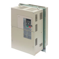
YASKAWA CIMR-A2A0004 Technical Manual (544 pages)
High Performance Vector Control Drive Models: 200 V Class: 0.4 to 110 kW 400 V Class: 0.4 to 355 kW
Brand:
YASKAWA
| Category:
Controller
| Size: 56.82 MB
Table of Contents
Table of Contents
5
Quick Reference
3
Table of Contents
5
I.1 Preface
16
Applicable Documentation
16
Symbols
16
Terms and Abbreviations
16
I.2 General Safety
17
Supplemental Safety Information
17
Safety Messages
18
Application Notes
19
Notes on Motor Operation
21
Applications with Specialized Motors
22
Drive Label Warnings
24
Warranty Information
24
Receiving
25
Section Safety
26
General Description
27
A1000 Model Selection
27
Control Mode Selection
28
Model Number and Nameplate Check
29
Nameplate
29
Drive Models and Enclosure Types
31
Component Names
32
IP20/NEMA Type 1 Enclosure
32
IP00 Enclosure
32
Front Views
35
Mechanical Installation
37
Section Safety
38
Installation Environment
40
2 Mechanical Installation
40
Installation Orientation and Spacing
40
Digital Operator Remote Usage
42
Exterior and Mounting Dimensions
46
Electrical Installation
51
Section Safety
52
Standard Connection Diagram
54
Main Circuit Connection Diagram
56
Three-Phase 200 V Class (CIMR-A 2A0169 to
56
Three-Phase 400 V Class (CIMR-A 4A0088 to 0675)
56
Terminal Block Configuration
57
Terminal Cover
59
CIMR-A 2A0004 to 0081, 4A0002 to 0044 (IP20/NEMA Type 1 Enclosure)
59
CIMR-A 2A0110 to 0415, 4A0058 to 0675 (IP00 Enclosure)
60
Digital Operator and
61
Removing/Reattaching the Digital Operator
61
Removing/Reattaching the Front Cover
61
Top Protective Cover
64
Reattaching the Top Protective Cover
64
Removing the Top Protective Cover
64
Main Circuit Wiring
65
Main Circuit Terminal Functions
65
Protecting Main Circuit Terminals
65
Wire Gauges and Tightening Torque
66
Main Circuit Terminal and Motor Wiring
70
Control Circuit Wiring
72
Control Circuit Connection Diagram
72
Control Circuit Terminal Block Functions
72
Terminal Configuration
73
Wiring the Control Circuit Terminal
74
Switches and Jumpers on the Terminal Board
76
Control I/O Connections
77
Sinking/Sourcing Mode Selection for Safe Disable Inputs
77
Sinking/Sourcing Mode Switch for Digital Inputs
77
Using the Pulse Train Output
78
Terminal A2 Input Signal Selection
79
Terminal A3 Analog/Ptc Input Selection
79
Terminal AM/FM Signal Selection
79
Memobus/Modbus Termination
80
Connect to a Pc
81
External Interlock
82
Drive Ready
82
Wiring Checklist
83
Start-Up Programming & Operation
85
Section Safety
86
Keys and Displays
87
Using the Digital Operator
87
LCD Display
88
ALARM (ALM) LED Displays
89
LO/RE LED and RUN LED Indications
89
Menu Structure for Digital Operator
90
The Drive and Programming Modes
91
Navigating the Drive and Programming Modes
91
Changing Parameter Settings or Values
92
Verifying Parameter Changes: Verify Menu
94
Simplified Setup Using the Setup Group
95
Switching between LOCAL and REMOTE
96
Start-Up Flowcharts
98
Flowchart A: Basic Start-Up and Motor Tuning
98
Subchart A-1: Simple Motor Setup Using V/F Control
99
Subchart A-2: High Performance Operation Using OLV or CLV
100
Subchart A-3: Operation with Permanent Magnet Motors
101
Powering up the Drive
102
Powering up the Drive and Operation Status Display
102
Application Selection
103
Setting 1: Water Supply Pump Application
103
Setting 2: Conveyor Application
103
Setting 3: Exhaust Fan Application
104
Setting 4: HVAC Fan Application
104
Setting 5: Compressor Application
105
Setting 6: Hoist Application
105
Notes on Controlling the Brake When Using the Hoist Application Preset
106
Setting 7: Traveling Application
108
Auto-Tuning
109
Types of Auto-Tuning
109
Before Auto-Tuning the Drive
111
Auto-Tuning Interruption and Fault Codes
112
Auto-Tuning Operation Example
112
Parameter Settings During Induction Motor Auto-Tuning: T1
114
Parameter Settings During PM Motor Auto-Tuning: T2
116
Parameter Settings During Inertia and Speed Control Loop Auto-Tuning: T3
119
No-Load Operation Test Run
121
Test Run with Load Connected
123
Test Run with the Load Connected
123
Verifying Parameter Settings and Backing up Changes
124
Backing up Parameter Values: O2-03
124
Parameter Access Level: A1-01
124
Password Settings: A1-04, A1-05
124
Copy Function
125
Test Run Checklist
126
Parameter Details
129
A1: Initialization
130
A: Initialization
130
A2: User Parameters
135
B1: Operation Mode Selection
136
B: Application
136
B2: DC Injection Braking and Short Circuit Braking
144
B3: Speed Search
146
B4: Delay Timers
151
B5: PID Control
152
B6: Dwell Function
161
B7: Droop Control (CLV, CLV/PM)
162
B8: Energy Saving
163
B9: Zero Servo
164
C1: Acceleration and Deceleration Times
165
C: Tuning
165
C2: S-Curve Characteristics
167
C3: Slip Compensation
167
C4: Torque Compensation
170
C5: Automatic Speed Regulator (ASR)
171
C6: Carrier Frequency
177
D: Reference Settings
180
D1: Frequency Reference
180
D2: Frequency Upper/Lower Limits
182
D3: Jump Frequency
182
D4: Frequency Reference Hold and Up/Down 2 Function
183
D5: Torque Control
188
D6: Field Weakening and Field Forcing
192
D7: Offset Frequency
193
E: Motor Parameters
194
E1: V/F Pattern for Motor 1
194
E2: Motor 1 Parameters
198
E3: V/F Pattern for Motor 2
201
E4: Motor 2 Parameters
202
E5: PM Motor Settings
204
F: Option Settings
206
F1: PG Speed Control Card Settings
206
F2: Analog Input Card Settings
209
F3: Digital Input Card Settings
209
F4: Analog Monitor Card Settings
210
F5: Digital Output Card Settings
211
F6: Communication Option Card
211
Canopen Parameters
213
CC-Link Parameters
213
Devicenet Parameters
213
H: Terminal Functions
214
MECHATROLINK Parameters
213
PROFIBUS-DP Parameters
213
H1: Multi-Function Digital Inputs
214
H2: Multi-Function Digital Outputs
224
H3: Multi-Function Analog Inputs
234
H4: Multi-Function Analog Outputs
239
H5: Memobus/Modbus Serial Communication
241
H6: Pulse Train Input/Output
241
L: Protection Functions
244
L1: Motor Protection
244
L2: Momentary Power Loss Ride-Thru
249
L3: Stall Prevention
255
L4: Speed Detection
262
L5: Fault Restart
263
L6: Torque Detection
264
L7: Torque Limit
267
L8: Drive Protection
269
N: Special Adjustments
275
N1: Hunting Prevention
275
N2: Speed Feedback Detection Control (AFR) Tuning
276
N3: High Slip Braking (HSB) and Overexcitation Braking
276
N5: Feed Forward Control
279
N6: Online Tuning
280
N8: PM Motor Control Tuning
281
O: Operator Related Settings
284
O1: Digital Operator Display Selection
284
O2: Digital Operator Keypad Functions
285
O3: Copy Function
287
O4: Maintenance Monitor Settings
288
Q: Driveworksez Parameters
289
R: Driveworksez Connection Parameters
289
T: Motor Tuning
290
U: Monitor Parameters
291
U1: Operation Status Monitors
291
U2: Fault Trace
291
U3: Fault History
291
U4: Maintenance Monitors
291
U5: PID Monitors
291
U6: Operation Status Monitors
291
U8: Driveworksez Monitors
292
Troubleshooting
293
Section Safety
294
Fine-Tuning Open Loop Vector Control
296
Fine-Tuning V/F Control and V/F Control with PG
296
Motor Performance Fine-Tuning
296
Fine-Tuning Closed Loop Vector Control
297
Fine-Tuning Open Loop Vector Control for PM Motors
297
Fine-Tuning Advanced Open Loop Vector Control for PM Motors
298
Fine-Tuning Closed Loop Vector Control for PM Motors
298
Parameters to Minimize Motor Hunting and Oscillation
299
Drive Alarms, Faults, and Errors
300
Types of Alarms, Faults, and Errors
300
Alarm and Error Displays
301
Fault Detection
306
Fault Displays, Causes, and Possible Solutions
306
Alarm Detection
319
Alarm Codes, Causes, and Possible Solutions
319
Operator Programming Errors
325
Ope Codes, Causes, and Possible Solutions
325
Auto-Tuning Fault Detection
328
Auto-Tuning Codes, Causes, and Possible Solutions
328
Copy Function Related Displays
332
Tasks, Errors, and Troubleshooting
332
Diagnosing and Resetting Faults
334
Fault Occurs Simultaneously with Power Loss
334
If the Drive Still Has Power after a Fault Occurs
334
Viewing Fault Trace Data after Fault
334
Fault Reset Methods
335
Troubleshooting Without Fault Display
336
Common Problems
336
Cannot Change Parameter Settings
336
Motor Does Not Rotate Properly after Pressing RUN Button or after
336
Entering External Run Command
337
Motor Is too Hot
338
Drive Does Not Allow Selection the Desired Auto-Tuning Mode
338
Ope02 Error Occurs When Lowering the Motor Rated Current Setting
338
Motor Stalls During Acceleration or Acceleration Time Is too Long
338
Reference Command
339
Excessive Motor Oscillation and Erratic Rotation
339
Deceleration Takes Longer than Expected with Dynamic Braking Enabled
339
Load Falls When Brake Is Applied (Hoist-Type Applications)
339
Noise from Drive or Output Lines When the Drive Is Powered on
340
Earth Leakage Circuit Breaker (ELCB) Trips During Run
340
Connected Machinery Vibrates When Motor Rotates
340
PID Output Fault
340
Insufficient Starting Torque
340
Output Frequency Is Not as High as Frequency Reference
341
Buzzing Sound from Motor at 2 Khz
341
Unstable Motor Speed When Using PM
341
Motor Does Not Restart after Power Loss
341
Periodic Inspection & Maintenance
343
Section Safety
344
Inspection
347
Recommended Periodic Inspection
348
Periodic Maintenance
349
Replacement Parts
349
Cooling Fan and Circulation Fan
351
Number of Fan
351
Cooling Fan Component Names
352
Cooling Fan Replacement: 2A0021 to 2A0081 and 4A0007 to 4A0044
353
Cooling Fan Replacement: 2A0110 and 2A0138, 4A0058 and 4A0072
355
Cooling Fan Replacement: 4A0088 and 4A0103
357
Cooling Fan Replacement: 2A0169 to 2A0415, 4A0139 to 4A0362
359
Cooling Fan Replacement: 4A0414
363
Cooling Fan Replacement: 4A0515 and 4A0675
365
Drive Replacement
369
Serviceable Parts
369
Terminal Board
369
Replacing the Drive
370
Peripheral Devices & Options
373
Section Safety
374
Drive Options and Peripheral Devices
375
Connecting Peripheral Devices
376
Installation Procedure
377
Installing Option Cards
377
Option Card Installation
377
Dynamic Braking Options
379
Installing Peripheral Devices
379
Installing a Molded Case Circuit Breaker (MCCB)
381
Installing a Magnetic Contactor
382
Connecting a Noise Filter
383
Connecting an AC or DC Reactor
383
Attachment for External Heatsink
385
Installing Input Fuses
385
Installing a Motor Thermal Overload (Ol) Relay on the Drive Output
386
Appendix: a
387
A. Specifications
387
Heavy Duty and Normal Duty Ratings
388
Three-Phase 200 V Class Drives
389
Three-Phase 400 V Class Drives
390
A.4 Drive Specifications
391
Drive Specifications
391
Drive Watt Loss Data
393
Carrier Frequency Derating
394
Drive Derating Data
394
Temperature Derating
395
Altitude Derating
396
Appendix: B
397
B. Parameter List
397
Control Modes, Symbols, and Terms
398
This Appendix Contains a Full Listing of All Parameters and Settings Available in the Drive.
398
Understanding the Parameter Table
398
B.2 Parameter Groups
399
Parameter Groups
399
Parameter Table
400
B.3 Parameter Table
400
A: Initialization Parameters
400
B: Application
401
C: Tuning
406
D: References
411
E: Motor Parameters
414
F: Options
418
H Parameters: Multi-Function Terminals
423
L: Protection Function
434
N: Special Adjustment
439
O: Operator Related Settings
442
Q: Driveworksez Parameters
444
R: Driveworksez Connection Parameters
444
T: Motor Tuning
444
U: Monitors
447
Control Mode Dependent Parameter Default Values
454
A1-02 (Motor 1 Control Mode) Dependent Parameters
454
E3-01 (Motor 2 Control Mode) Dependent Parameters
455
V/F Pattern Default Values
456
Defaults by Drive Model Selection (O2-04) and Nd/Hd (C6-01)
457
Parameters that Change with the Motor Code Selection
463
YASKAWA SMRA Series SPM Motor
463
YASKAWA SSR1 Series IPM Motor (for Derated Torque)
464
YASKAWA SST4 Series IPM Motor (for Constant Torque)
470
C. Memobus/Modbus Communications
477
C.1 Memobus/Modbus Configuration
478
C.2 Communication Specifications
479
C.3 Connecting to a Network
480
Network Cable Connection
480
Wiring Diagram for Multiple Connection
480
Network Termination
481
C.4 Memobus/Modbus Setup Parameters
482
Memobus/Modbus Serial Communication
482
C.5 Drive Operations by Memobus/Modbus
485
Observing the Drive Operation
485
Controlling the Drive
485
C.6 Communications Timing
486
Command Messages from Master to Drive
486
Response Messages from Drive to Master
486
C.7 Message Format
487
Message Content
487
Slave Address
487
Function Code
487
Data
487
Error Check
487
C.8 Message Examples
489
Reading Drive Memobus/Modbus Register Contents
489
Loopback Test
489
Writing to Multiple Registers
489
C.9 Memobus/Modbus Data Table
491
Command Data
491
Monitor Data
492
Broadcast Messages
500
Fault Trace Contents
500
Alarm Register Contents
501
C.10 Enter Command
503
Enter Command Types
503
Enter Command Settings When Upgrading the Drive
503
C.11 Communication Errors
504
Memobus/Modbus Error Codes
504
Slave Not Responding
504
C.12 Self-Diagnostics
505
D. Standards Compliance
507
D.1 Section Safety
508
D.2 European Standards
510
CE Low Voltage Directive Compliance
510
EMC Guidelines Compliance
510
D.3 UL Standards
515
UL Standards Compliance
515
Drive Motor Overload Protection
516
D.4 Safe Disable Input Function
518
Specifications
518
Precautions
518
Using the Safe Disable Function
518
Disable Monitor Output Function/Digital Operator Display
520
E. Quick Reference Sheet
521
Drive Specifications
522
E.1 Drive and Motor Specifications
522
Basic Setup
523
E.2 Basic Parameter Settings
523
Monitor Outputs
523
Motor Setup
523
Multi-Function Digital Inputs
523
Multi-Function Digital Outputs
523
Pulse Train Input/Analog Inputs
523
V/F Pattern Setup
523
E.3 User Setting Table
524
Index
529
Revision History
543
Related Products
YASKAWA CIMR-A2A0006
YASKAWA CIMR-A2A0010
YASKAWA CIMR-A2A0012
YASKAWA CIMR-A2A0021
YASKAWA CIMR-A2A0030
YASKAWA CIMR-A2A0040
YASKAWA CIMR-A2A0056
YASKAWA CIMR-A2A0069
YASKAWA CIMR-A2A0081
YASKAWA CIMR-A2A0169
YASKAWA Categories
Controller
DC Drives
Servo Drives
Robotics
Control Unit
More YASKAWA Manuals