beautypg.com
Manuals
Brands
Siemens Manuals
Controller
SIMATIC S5-95U
Siemens SIMATIC S5-95U Manuals
Manuals and User Guides for Siemens SIMATIC S5-95U. We have
3
Siemens SIMATIC S5-95U manuals available for free PDF download: System Manual, Manual
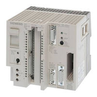
Siemens SIMATIC S5-95U System Manual (622 pages)
Brand:
Siemens
| Category:
Controller
| Size: 6.86 MB
Table of Contents
Table of Contents
7
How to Use this System Manual
17
System Description
21
Table of Contents
22
1 System Description
25
All Inputs and Outputs
26
Retentive and Non-Retentive Operands
27
Software Overview
28
Communications Capabilities
29
Design of the S5-90U/Design of the S5-95U
33
2 Technical Description
35
Programmable Controller Design - Without External I/Os
35
Design of the S5-90U
35
Design of the S5-95U
37
Internal Electrical Configuration
39
Internal Electrical Configuration of the S5-90U
39
2.2.2 Internal Electrical Configuration of the S5-95U
40
Principle of Operation of the Plcs
41
Functional Units
41
Peculiarities of the Plcs
44
Installation Guidelines/Mounting the Plcs with External I/Os
47
3 Installation Guidelines
47
Mounting the PLC
47
Mounting the Plcs with External I/Os
47
Mounting the S5-90U with External I/Os
47
Mounting the S5-95U with External I/Os
47
Wiring
47
Connecting the Power Supply to the S5-90U
47
Connecting the Power Supply to the S5-95U
47
Cabinet Mounting
61
Connection Methods
63
3.3.4 Connecting the Onboard I/Os of the S5-90U
68
3.3.5 Connecting the Onboard I/Os of the S5-95U
70
Connecting External I/Os
72
Electrical Configuration with External I/Os
73
Electrical Configuration of the S5-90U with External I/Os
73
Electrical Configuration of the S5-95U with External I/Os
75
3.4.3 Connecting Non-Floating and Floating Modules
78
Wiring Arrangement, Shielding and Measures against Electromagnetic Interference
81
Running Cables Outside Buildings
82
Equipotential Bonding
83
Shielding Cables
84
Special Measures for Interference-Free Operations
85
Start-Up and Programmer Functions/Operating Instructions
87
4 Start-Up and Programmer Functions
87
Operating Instructions
87
Operating Modes
90
Start-Up and Program Tests
90
Performing an Overall Reset of the Programmable Controller
91
Starting up a System
92
Suggestions for Configuring and Installing the Programmable Controller
92
Steps for Starting up the Programmable Controller
93
Loading the Program into the PLC
96
Loading the Program Automatically
96
Loading the Program Manually
97
Saving a Program
98
Saving a Program to a Memory Submodule
98
Function of the Back-Up Battery
99
Programmer Functions
99
Overview of Programmer Functions
100
Peculiarities of the Programmer Functions for the S5-90U and S5-95U
101
Diagnostics and Trouble Shooting/Diagnostic Byte
103
5 Diagnostics and Trouble Shooting
103
Diagnostic Byte
103
LED Error Display
103
Interrupt Analysis Using the Programmer
103
ISTACK" Analysis Function
103
Meanings of the ISTACK Displays for Errors Occurring
103
Meanings of the ISTACK Displays in the Case of Errors
103
S5-90U and S5-95U
110
Meanings of the ISTACK Displays for Errors Occurring During Restart and Program Execution
111
During Copying the Program
112
Meanings of the ISTACK Displays in the Case of Errors During Copying the Program
112
Program Errors
113
Determining an Error Address
113
5.4.2 Program Tracing with the "BSTACK" Function
114
Faults in the External I/Os
116
System Parameters
117
The PLC Does Not Enter the "RUN" Mode
117
Addressing and Access to I/Os
119
6 Addressing and Access to I/Os
121
Addressing the Onboard I/Os
121
Addressing the External I/Os
122
Slot Numbering
122
Digital Modules
125
Analog Modules
127
Function Modules
128
Process Image and Access to I/Os
129
Access to I/Os During Cyclic Program Execution
131
Access to I/Os During Time-Controlled Program Execution
133
(For S5-95U Only)
133
Access to I/Os During Time-Controlled Program Execution (for S5-95U Only)
133
Calculating the Scan Time and Response Time
135
Start-Up With/Without External I/Os and Parameterization of Internal Timers (S5-95U Only)
143
Introduction to Step 5
145
Methods of Representation
147
STEP 5 Operations
147
Writing a Program
147
Operand Areas
148
Linear Programming
149
Program Structure
149
Structured Programming
150
Block Types
152
Organization Blocks (Obs)
154
Function Blocks (Fbs)
156
Program Blocks (Pbs)
156
Sequence Blocks (Sbs; Only for S5-95U)
156
Data Blocks (Dbs)
161
Changing Blocks
163
Changing Programs
163
Compressing the Program Memory
163
Processing Blocks
163
Number Representation
164
Table of Contents
167
8 STEP 5 Operations
169
Basic Operations
169
Boolean Logic Operations
170
Set/Reset Operations
175
Load and Transfer Operations
178
Timer Operations
183
Counter Operations
193
8.1.6 Comparison Operations
198
Arithmetic Operations
199
Block Call Operations
201
Other Operations
206
Supplementary Operations
207
Load Operation (Only for the S5-95U)
208
Enable Operation (Only for the S5-95U)
209
Bit Test Operations (Only for the S5-95U)
210
Digital Logic Operations
212
Shift Operations
216
Conversion Operations
218
Decrement/Increment (Only for the S5-95U)
220
Disable/Enable Interrupt
221
DO Operation (Only for the S5-95U)
222
8.2.10 Jump Operations
224
Substitution Operations (Only for the S5-95U)
226
System Operations (Only for the S5-95U)
232
Set Operations (Only for the S5-95U)
232
Load and Transfer Operations
232
Arithmetic Operation (Only for the S5-95U)
235
Other Operations (Only for the S5-95U)
236
Condition Code Generation
237
Sample Programs
239
Momentary-Contact Relay (Edge Evaluation)
239
Binary Scaler (Binary Divider)
239
Clock (Clock-Pulse Generator)
241
Integrated Blocks and Their Functions
243
Integrated Blocks and Their Functions
245
Cyclic Program Execution (OB1)
246
Interrupt-Driven Program Execution (OB3)
247
Time-Controlled Program Execution (OB13; for S5-95U Only)
247
Restart Processing (OB21, OB22)
249
Retriggering the Scan Time (OB31; for S5-95U Only)
250
Procedure after Battery Failure (OB34; for S5-95U Only)
251
OB251 PID Algorithm (for S5-95U Only)
252
Code Converter
264
Integrated Function Blocks (Fbs)
264
Code Converter : 16 - FB
265
Integrated Sequence Block 2 (SB2)
268
Output of Analog Values (FB251)
268
Reading of Analog Values (FB250)
268
Integrated Data Block 1 (DB1)
269
Parameter Blocks
270
Rules to Observe When Generating DB1
271
Procedure for Parameterizing the PLC
274
Transferring DB1 Parameters to the Programmable Controller
274
9.4.5 How to Recognize and Correct Parameter Errors
275
10 Onboard Interrupt Inputs
279
Onboard Interrupt Inputs
281
Interrogating the Cause for an Interrupt in the Diagnostic Byte
282
Interrupt Priority
284
Calculating Interrupt Reaction Times
287
Onboard Counter Inputs
289
11 Onboard Counter Inputs
291
11.1 Setting Parameters for Counter Inputs in DB1
293
Programming the Reaction to Interrupts in OB3
294
Scanning the Actual Counter Status
295
Entering the Comparison Value and Resetting the Counter
295
Cascading Counters (with the S5-95U Only)
297
Calculating the Counter Frequency Limit
299
Analog Value Processing
301
12 Analog Value Processing
303
Reading in Analog Values
304
12.1.1 General Representation of Analog Input Values
305
12.1.2 Reading in and Scaling an Analog Value -FB250
307
Time Required for Reading and Accuracy of the Analog Value Read in
309
12.1.4 Using Analog Inputs of the S5-95U as Additional Digital Inputs
310
Output of Analog Values
311
12.2.1 General Representation of Analog Output Values
311
12.2.2 Outputting Analog Values -FB251
312
12.2.3 Time Required for Output and Accuracy of the Analog Value Output
314
Example: Analog Value Processing with FB250 and FB251
316
13 Integral Real-Time Clock (Only in the S5-95U)
323
Function
323
13.2 Structure of the Clock Data Area
324
Structure of the Status Word and How to Scan It
327
Backup of the Hardware Clock
329
Setting Parameters in DB1
330
Setting the Clock in DB1
332
Setting the Operating Hours Counter in DB1
333
Programming the Integral Real-Time Clock in the User Program
334
Programming the Prompt Function
338
Programming the Operating Hours Counter
343
Entering the Clock Time Correction Factor
348
14 Communication Via SINEC L1 LAN
349
Communication Via SINEC L1 LAN
351
Connection of the Programmable Controllers to the L1 Bus Cable
352
Basic Principle of Data Interchange
353
Sending Data
355
Receiving Data
357
Program Example
359
15 Module Spectrum
363
Module Spectrum
367
General Technical Specifications
369
Power Supply Modules
370
Bus Units
372
Interface Modules
374
Digital Modules
377
Digital Input Modules
379
Digital Output Modules
389
Digital Input/Output Modules
400
Analog Modules
402
Analog Input Modules
403
Analog Output Modules
458
16 Function Modules
467
Function Modules
469
Timer Module
472
Simulator and Simulator Module
475
Simulator Module
476
Diagnostic Module
478
Counter Module 2×0 to 500 Hz
481
Counter Module 25/500 Khz
486
Installation Guidelines
489
Data Transfer
494
Functional Description of the Counter Mode
496
Functional Description of the Position Decoder
498
Entering New Setpoints for the Counter and Position Decoder
507
Addressing
508
IP 262 Closed-Loop Control Module
510
IP 263 Positioning Module
514
IP 264 Electronic Cam Controller Module
518
IP 265 High Speed Sub Control
521
IP 266 Positioning Module
524
IP 267 Stepper Motor Control Module
528
CP 521 si Communications Processor
531
CP 521 BASIC Communications Module
534
A Operations List, Machine Code and List of Abbreviations
537
A.1 Operations List
541
A.1.2 Supplementary Operations
548
A.1.3 System Operations
553
A.1.4 Evaluation of CC 1 and CC 0
554
A.2 Machine Code Listing
555
A.3 List of Abbreviations
558
B Technical Specifications, DB1 Parameters, RAM Address Assignment
565
B.1.2 Technical Specifications S5-90U
566
B.1.3 Technical Specifications S5-95U
567
B.2 DB1 Parameters
569
B.2.2 DB1 Parameters of S5-95U
570
B.3 RAM Address Assignment
572
B.3.2 RAM Address Assignment in the S5-95U
574
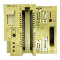
Siemens SIMATIC S5-95U Manual (224 pages)
Interface of the Programmable Controller
Brand:
Siemens
| Category:
Controller
| Size: 1.24 MB
Table of Contents
Table of Contents
4
Preface
8
System Description
11
1 System Description
13
Communications in Industry
13
Hierarchy Levels in the Computer-Integrated Automation Network
13
The SINEC L2 Local Area Network
15
Bus Segment
15
Procedure for Accessing the SINEC L2 Network
16
Bus Accessing Procedure
17
Distribution of the Target Rotation Time
19
Assigning Parameters for the L2 Interface of the S5-95U
20
DB1 with the Default Parameters
20
DB1 Basic Parameters
21
Defining the Basic Parameter Arguments for S5-95U Plcs
22
Defining the Arguments of the Basic Parameters for the S5-95U in Conjunction with the CP 5410 And/Or CP 5430-1
24
Basic Parameter Arguments for the S5-95U in Conjunction with Other SIMATIC Devices
24
Types of Data Transmission for the S5-95U
25
Data Transmission Types
25
Recommended Types of Data Transmission
26
Characteristics of the Various Types of Data Transmission
27
Types of Data Transmission for S5-95Us as Active Stations
28
Types of Data Transmission for S5-95Us as Passive Stations
29
PLC-To-PLC Connection between Active S5-95Us
30
Standard Connection for Porting Programs from SINEC L1 to SINEC L2
31
PLC-To-PLC Connection between an Active CP 5430 and an Active S5-95U
31
Cyclic I/O between an Active CP 5430 and a Passive S5-95U
31
Layer 2 Access between an Active CP 5410 and an Active S5-95U
32
Physical Bus Characteristics and Installation Techniques for the SINEC L2 Network
33
RS 485 Transmission Technology
33
SINEC L2 Bus Segment with RS 485 Technology
33
SINEC L2 Network with RS 485 Technology
34
Distance Table for RS 485 Technology
34
L2 Bus Connector with Degree of Protection IP 20 Without Connector for a Programmer
35
SINEC L2 Bus Terminals
35
Technical Specifications of the Bus Cable
36
Fiber Optics Transmission Technology
37
SINEC L2 Network with Fiber Optic Cable
37
SINEC L2FO Bus Terminal SF-B/PF-B
38
Distance Table for Glass Fiber Optic Cable Technology
38
SINEC L2FO Active Star Coupler as
39
Mixed Configuration of RS 485 and Fiber Optics Transmission Technology
40
Mixed Configuration RS 485 and Fiber Optics Transmission Technology
40
Mixed Configuration with RS 485 and FO Transmission Technology
40
Via Fiber Optic Cable
40
SINEC L2FO SF Repeater Adapter for L2 Repeater
41
2 Installation Guidelines
43
Basic Configuration
43
Installing a SINEC L2 Bus Segment
43
Electrical Design of the SINEC L2 Repeater RS 485
43
Installation Guidelines
45
Connecting the Supply Voltage
49
Connecting Bus Segments
50
Routing Cables
52
Starting up a System
53
Suggestions for Configuring and Installing the Equipment
53
Prerequisites for Starting up the S5-95U as a SINEC L2 Station
53
System Startup Diagnostics and Procedures
53
FMA Services
53
Principle of Operation
53
The Types of FMA Services
53
Assigning Parameters in DB1 for the FMA Services
53
Managing of All FMA Services with FB222
53
Reading out a List of All Active Stations on the Network (LAS_LIST_CREATE)
53
Start-Up, Tests, and Diagnostics
55
START-UP Sequence
58
Starting up a System
59
Suggestions for Configuring and Installing the Equipment
59
Prerequisites for Starting up the S5-95U as a SINEC L2 Station
60
System Startup Diagnostics and Procedures
61
Principle of Operation
64
Reading out a List of All Active Stations on the Network (LAS_LIST_CREATE)
71
Reading the Status of Another Station (FDL_STATUS)
73
Reading Updated Bus Parameters (READ_VALUE)
75
Reading out Available Token Hold Time When Receiving the Token
78
Reading out the Event Message (MAC_EVENT)
80
4 Data Transmission Using a Standard Connection
85
Features of a Standard Connection
85
Assigning Parameters in DB1 of the S5-95U for Data Exchange with
87
Standard Connections
87
Transmitting Data
89
Receiving Data
91
Programming Example for Data Transmission Via a Standard Connection
93
Broadcast Request ("Transmit to All")
98
5 Integral Standard Function Blocks L2-SEND and L2-RECEIVE
101
Parameters for L2-SEND and L2-RECEIVE
102
Direct and Indirect Parameter Settings for the L2 Function Blocks
104
Parameter Assignment Error Byte (PAFE)
105
Status Byte
106
6 Data Transmission Using PLC-To-PLC Connections
108
Features of the PLC-To-PLC Connections
108
Assigning Parameters in DB1 of the S5-95U for Data Exchange
108
With PLC-To-PLC Connections
108
Programming Example for Data Transmission Via PLC-To-PLC Connections Using Standard Function Blocks
108
Assigning Parameters in DB1 of the S5-95U for Data Exchange with PLC-To-PLC Connections
113
Data Transmission Using Cyclic I/O
122
Features of Cyclic I/O
122
Assigning Parameters in DB1 of the S5-95U for Data Exchange
122
With Cyclic I/O
122
Data Transmission Using Cyclic I/O
124
Assigning Parameters in DB1 of the S5-95U for Data Exchange with Cyclic I/O
127
Controlling Data Transmission in the Control Program
130
Programming Example for Data Transmission Via Cyclic I/O
135
8 Data Transmission by Accessing Layer 2 Services
139
Characteristic Features of Layer 2 Access Data Transmission
139
Types and Characteristic Features of the Layer 2 Services
139
Assigning the S5-95U Parameters for Data Communications
139
Fbs for Managing All Layer 2 Services
139
Sending Data to a Station (SDA Service)
139
Sending Data to Several Stations (SDN)
139
Holding Data for Fetching Once Only by a Station (RUP_SINGLE Service)
139
Holding Data Ready for Fetching Several Times over by One
139
Data Transmission by Accessing Layer 2 Services
141
Sending Data and Fetching Data from a Station (SRD Service)
169
Programmer Functions over the SINEC L2 Network
174
Programmer Functions over the SINEC L2 Network
176
9 Programmer Functions over the SINEC L2 Network
177
Programmer Functions
177
Selecting the L2 Interface
178
Entering Defaults
179
Editing a Path
180
Setting the L2 Basic Parameters on the Programmer
185
Activating an Editing Path
185
Appendices
186
ADB1 Parameters, DB1 Parameter Assignment Errors
188
Calculation of Target Rotation Time
188
BSAP Numbers / Job Numbers
196
C List of Abbreviations/Glossary
199
List of Abbreviations/Glossary
200
List of Accessories and Order Numbers
208
E Technical Specifications; Cycle Delay Times of the PLC Caused by SINEC L2 Operations
210
F S5-95U Communications Matrix and Emulation of Types of Data
215
Siemens SIMATIC S5-95U Manual (109 pages)
Second Serial Interface of the Programmable Controller
Brand:
Siemens
| Category:
Controller
| Size: 0.9 MB
Table of Contents
Introduction 1 2 3
4
Table of Contents
4
Introduction
6
Section 2
10
1 Description of the System
11
Possible Applications of the S5-95U with Second Serial Interface
12
Device Configurations
12
Criteria for Selecting the Communications Mechanism
13
Characteristics of the Communications Mechanisms
14
Range of Functions of the Two Serial Interfaces
15
Overview of the Functions Possible at SI1 and SI2 Interfaces
15
Configuration of the PLC and Assignment of the Second Serial Interface
17
S5-95U Leds, Controls and Interfaces
17
Pin Assignments of the Second Serial Interface of the S5-95U
18
2 Point-To-Point Link with SINEC L1 Protocol
21
Data Traffic and DB1 Parameter Assignment in a Point-To-Point Link
26
Coordination Bytes in a Point-To-Point Link
27
Program Example of Point-To-Point Link
28
Section 3
32
3 Computer Link with 3964(R) Transmission Protocol
33
Connection of Communication Partners in a Computer Link
35
Communication Partner (TTY Passive)
35
Communication Partner (TTY Active)
36
Data Traffic Via Computer Link
37
Coordination Bytes for a Computer Link
39
Error Messages in the "Send" Coordination Byte
40
Error Messages in the "Receive" Coordination Byte
41
Parameterizing the Computer Link in DB1
42
Computer Link, DB1 Parameters
43
(Depending on Data Format)
45
Sample Program for Computer Link
47
The 3964(R) Transmission Protocol
50
4 ASCII Driver
60
Connection of Communication Partners When Using the ASCII Driver
61
Data Traffic with the ASCII Driver
63
Coordination Bytes for Use of the ASCII Driver
65
Parameterizing the ASCII Driver in DB1
67
Program Example for the ASCII Driver
76
Appendices
83
ADB1 Parameters, DB1 Parameterizing Errors a
84
B Positions of the Parameters in the System Data Area of the PLC, ASCII Code B
88
C List of Abbreviations C
95
D Accessories and Order Numbers D
98
Second Serial Interface
99
Index
105
Related Products
Siemens SIMATIC S5-90U
Siemens SIMATIC S5-95F
Siemens S55499-D166
Siemens S55499-D460
Siemens S55625-H444-A100
Siemens S55499-D386
Siemens S55499-D399
Siemens S55499-D400
Siemens S55155-A111
Siemens S55180-A148
Siemens Categories
Industrial Equipment
Controller
Control Unit
Oven
Washer
More Siemens Manuals