beautypg.com
Manuals
Brands
Motorola Manuals
Touch terminals
Malux MTM5400 Series
Motorola Malux MTM5400 Series Manuals
Manuals and User Guides for Motorola Malux MTM5400 Series. We have
3
Motorola Malux MTM5400 Series manuals available for free PDF download: Installation Manual, Feature User Manual
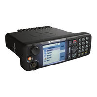
Motorola Malux MTM5400 Series Feature User Manual (133 pages)
Mobile Release 10.6
Brand:
Motorola
| Category:
Radio
| Size: 5.28 MB
Table of Contents
Table of Contents
3
General Information
13
Safety Information
13
Copyrights
13
Icon Conventions
14
Getting Started
17
Using this Guide
17
Table 2-1 Special Notations
17
Product Specific Information
18
Table 2-2 Product Specific Information
18
Controls and Indicators
19
Table 2-3 Controls and Indicators
20
Display
21
Table 2-4 Display
21
Status Icons
22
Table 2-6 Status Icons
22
Powering on the Radio
25
Unlocking Your Radio
25
Unblocking Your Radio
26
Locking/Unlocking the Keys/Buttons
26
Entering TMO / DMO Mode
26
Transmit Inhibit Mode
27
Selecting a Talkgroup
27
Using Timed Talkgroup Change
28
Activating Talkgroup Scanning
28
Writing Text
29
Selecting Text Entry Mode
29
Selecting Text Entry Method and Language
29
Text Entry Icons
30
Keys Usage
30
Table 2-8 Keys Usage
31
Table 2-9 Other Keys
31
Writing in Itap Alphanumeric
32
Writing in TAP Alphanumeric
33
Word Locking
33
Adding Words to the Dictionary
34
Broadcast Call
34
Ambience Listening (AL) Call
34
One-Touch Button Feature
34
Table 2-10 One-Touch Button Features
34
Terminal Disable/Enable
35
Terminal Permanent Disable
35
During the Call
36
Home Display Text Message
36
Table 2-11 During the Call
36
Modes
37
Using Networks
37
Trunked Mode Operation
37
Entering TMO Mode
38
Selecting a Talkgroup
38
Figure 3-1 Trunked Mode Operation
38
Making a Group Call
39
Receiving a Group Call in Idle
39
Receiving a Group Call During an Ongoing Group Call
39
Dynamic Group Number Assignment (DGNA)
39
DGNA Reception
40
DGNA Auto Select Group
40
Viewing DGNA Talkgroups
40
Broadcast Call Initiated by User
40
Initializing Broadcast Call
40
Phone and PABX Calls
41
Private Call
41
Assistance Call
41
Local Site Trunking
41
Entering Local Site Trunking
42
Exiting Local Site Trunking
42
Direct Mode Operation
42
Entering DMO Mode
43
Selecting a Talkgroup
43
Making a Group Call
43
Figure 3-2 Direct Mode Operation
43
Receiving a Group Call in Idle
44
Private Call
44
Private Call with Presence Check
44
Communication through Repeater
44
Communication through Gateway
45
Selecting DMO Group Call Options
45
Transmit Inhibit Mode
46
Emergency Mode
47
Emergency Operation
47
Silent Emergency Mode
48
Emergency Group Call
48
Emergency Private Call
49
Emergency MS-ISDN Call
49
Emergency Alarm
49
Hot Microphone
49
Alternating Hot Microphone
50
Entering Emergency Mode
50
Emergency Mode by Dialing
50
Exiting Emergency Mode
51
Making an Emergency Group Call
51
Receiving an Emergency Group Call
51
Disaster Alert Call
51
Initializing Disaster Alert Call
52
Repeater Mode
52
Figure 3-3 Repeater Mode Operation
52
Entering Repeater Mode
53
Setting Monitor Option
53
Gateway Mode
53
Figure 3-4 Gateway Mode Operation
53
Emergency Calls in Gateway Mode
54
Entering Gateway Mode
54
Forwarding a Group Call
54
Setting Monitor Option
54
Standby Mode
54
GPS Location Service
55
Enhancing GPS Performance
56
Enabling GPS
56
GPS Icon
57
GPS Different Location Displays
57
Viewing Your Position
58
GPS - Things to Keep in Mind
58
Main Menu
59
Scrolling through the Menu
59
Menu Icons
60
Menu Structure
60
Table 5-1 Menu Icons
60
Table 5-2 Menu Structure
60
Messages
64
New Message
64
Sending a Message to Private/Phone
64
Sending a Message to Group
64
Sending a Store and Forward Message
65
Inbox
65
Table 5-3 Inbox Icons
65
Entering the Inbox
66
Receiving New Message
66
Using Submenu in Inbox and Outbox
66
Embedded Number
67
Storing a Number from a Message
67
Calling a Number in a Message
68
Immediate Message
68
Making a Group Call on a Talkgroup of the Message Originator
68
Outbox
69
CO Box
69
WAP Box
69
Templates
69
Sending a User-Defined Template
69
Setting User-Defined Templates
70
Predefined Templates
70
Viewing Predefined Templates
70
Sending Predefined Templates
71
Send Status
71
Viewing a Status Message Number
71
Sending a Status Message to a Group
71
Targeted Status
72
Sending a Targeted Status Message
72
Contacts
72
Creating a Contact
73
Table 5-5 Contact Types
73
Editing a Contact
74
Deleting a Number
74
Deleting a Contact
74
Checking Capacity
75
Dialing through the Contact List
75
Security
75
PIN Protect
76
Protecting the Radio with a PIN Code
76
Unblocking Your Radio
76
Changing PIN Code
76
Keylock Setup
77
Keypad Lock Notification
77
Setting Automatic Keylock Delay
77
Setting Keylock on Startup
77
Air Encryption
78
Viewing Air Encryption State
78
Air Encryption Key Deletion
78
K Validity
78
Verifying K Validity
78
TMSCK Validity
79
Verifying TMSCK Validity
79
DMSCK Validity
79
Verifying DMSCK Validity
79
Dmo Sck
80
Changing DMO SCK
80
Covert Mode
80
Activating Covert Mode
81
Setup
81
Ring Style
81
Setting Ring Style
81
Set Volume
82
Setting Volume
82
Language
82
Setting Language
83
Data Setup
83
Setting Data Function
83
Audio
83
Volume Adjustment Mode
83
Setting Volume Adjustment Mode
84
Tones
84
Keypad Tone
84
Setting Keypad Tone
84
All Tones
84
Setting All Tones
85
Talk Permit
85
Setting Talk Permit
85
Clear to Send
85
Setting Clear to Send
85
Periodic Alert
85
Setting Periodic Alert
86
D-PTT Tones
86
Setting D-PTT Tones
86
Display
86
Setting Text Size
86
Setting Screen Saver
87
Setting Backlight
87
Setting Wallpaper
87
Time and Date
88
Setting Time and Date on the Display
88
Setting Time Format
88
Setting Time Manually
89
Setting Date Format
89
Setting Date Manually
89
Setting Time Offset
90
Setting Automatic Update for the Time and Date
90
Accry (Accessory) Type
90
Selecting Accessory Type
90
Book on
91
Editing Book on Settings
91
Rotary Knob
91
Setting Rotary Knob Mode
91
Setting Rotary Lock
92
Setting in Keypad Lock
92
Setting Rotary Knob Wrap Around
93
Setting Rotary Knob Scroll Range
93
Setting Rotary Knob Talkgroup Selection
93
Group Setup
94
Scan
94
Activating Talkgroup Scanning
94
Setting Talkgroups in the Active Scan List
94
Setting Scan Lists
95
Editing Scan Lists
95
My Groups
96
Adding Favorite Folder
96
Adding a Talkgroup to a Favorite Folder
96
Editing My Folder List
96
Deleting a Talkgroup from the Favorite Folder
97
My Info
97
Viewing/Modifying Personal Information
97
Recent Calls
98
Viewing Recent Calls
98
Calling from Recent Calls
99
Storing Recent Calls to Contacts
99
Deleting Recent Calls
100
Shortcuts
100
Creating a Menu Shortcut
100
Editing a Menu Shortcut List
101
Rui
101
Logging on
102
Logging off
102
Networks
102
Selecting Your Network
103
Using the Select Net Registration
103
Using the Foreign Network Registration
103
Using any Network
103
Using the Migrate to Registration
104
Selecting Network Operation Mode
104
Location
105
Viewing Your Position
105
Packet Data
105
Viewing Data Statistics
106
Viewing Encryption Status
106
Wap
107
WAP Browser
107
Entering/Exiting the Browser
107
Entering the Browser Menu Panes
108
Tips for Browsing
108
Creating a Bookmark through Navigate Pane
108
Creating a Bookmark through Bookmarks Pane
109
Using a Bookmark
109
Creating a Hotkey
109
Using a Hotkey
110
Saving a Page
110
Selecting a Saved Page
110
Disabled Packet Data Service
110
Disabled Browser Entry
111
Keys Usage
111
Table 6-1 Browser Keys Usage
111
Browser Menu Panes Overview
112
Table 6-2 Browser Menu Panes
112
Table 6-3 Additional Menu Panes
112
Navigate Pane
113
Advanced
113
Bookmarks Pane
114
Working with the Options Pane for a Selected Bookmark
114
Working with the Saved Pages Folder
114
History Pane
115
Navigating to the Recently Visited URL
115
Tools Pane
115
Options Pane
115
Image Pane
116
Text Input Pane
116
WAP Push
116
Table 6-4 Browser Text Input Icons
116
New WAP Messages
117
Viewing a WAP Message
117
Features
119
Call-Out
119
Types of Call-Out Alerts
119
Call-Out Modes Interaction
120
Call-Out Service Phases
120
Rua/Rui
120
DTMF Overdial
121
Talkgroup Dialing by Index
121
Viewing Talkgroup Speed Number
121
Selecting Talkgroup by Index
121
One-Touch Dial
122
Phone/Pabx Speed Dial
122
Using Phone/Pabx Speed Dial
122
Phone and PABX Calls
122
Making a Phone or PABX Call
122
Private Call
123
Making a Private Call
123
Short Number Dial
123
Dual Control Head
124
Master Single Control Head Mode
124
Slave Standalone Mode
124
Dual Control Head Link
124
Dual Control Head Keys Interactions
124
Dual Control Head Voice
125
Voice Operating Transmission (VOX) Control
125
Pseudo Call Forward
125
Appendix A Tones
127
Table A-1 Radio Tones
127
Table
128
Exiting Dmo
128
Appendix B LED Indications
129
Table B-1 LED Indications
129
Appendix C Troubleshooting
131
Table C-1 Displayed Messages
131
Motorola Malux MTM5400 Series Installation Manual (134 pages)
Brand:
Motorola
| Category:
Two-Way Radio
| Size: 8.1 MB
Table of Contents
Copyrights
3
Table of Contents
5
List of Figures
9
List of Tables
13
Icon Conventions
17
Chapter 1: Scope of this Manual
19
Safety Information
19
Mtm5X00 Manuals and User Guides
19
Chapter 2: Model Information and Accessories
23
Model Descriptions
23
Sales Model Nomenclature
23
Table 1: Radio Model Descriptions
23
Table 2: Sales Model Nomenclature
23
Table 3: Sales Models - Description of Symbols
23
Mobile Terminal Model Information
24
Table 4: Type and Model Numbers
24
Model Specifications
26
Table 5: General Specifications
26
Table 6: Receiver Specifications
27
Table 7: Transmitter Specifications
27
MTM5200/MTM5400 Accessories-To-Model Chart
28
Table 8: Control Heads
28
Table 9: Expansion and Remote Head Kits
29
Table 10: Microphones
29
Table 11: Loudspeakers
29
Table 12: Handsets
29
Table 13: PTT Switches
30
Table 14: Desktop and Data Box Mount
30
Table 15: Power Supplies
30
Table 16: Power Cables
30
Table 17: Cables
30
Table 18: Junction Box
31
Table 19: Power Cables (to Mobile Terminal)
31
Table 20: Installation
31
Table 21: Mounting (Transceiver)
31
Table 22: Mounting (Control Head)
32
Table 23: Programming/Data
32
Table 24: Antennas
32
MTM5500 Accessories-To-Model Chart
33
Table 25: GPS
33
Table 26: Motorcycle Enclosures
33
Table 27: Control Heads
33
Table 28: Microphones
34
Table 29: Loudspeakers
34
Table 30: Handsets
34
Table 31: PTT Switches
35
Table 32: Cables
35
Table 33: Power Cables (to Mobile Terminal)
35
Table 34: Installation
35
Table 35: Mounting (Transceiver)
36
Table 36: Mounting (Control Head)
36
Table 37: Programming/Data
36
Table 38: Antennas
36
Table 39: GPS
37
Table 40: Label Identification for Telephone Style Control Head
37
Table 41: Ferrites for Ethernet Control Head
38
Chapter 3: Vehicle Preparation
39
General Guidelines for Radio Installation
39
Uninstalling the Radio
40
Installing DC Power Cable
40
Figure 1: Power Cabling Routing to Engine Compartment
41
Figure 2: Power Cable Assembly
42
DC Power Cables
43
Installing Ignition Sense Cable
43
Table 42: DC Power Cables
43
Figure 3: Accessory Plug
44
Ignition Sense Cables
44
Table 43: Ignition Sense Cables
44
Chapter 4: Radio Installation
45
Dashboard Installation
45
Installing the Radio in an Automotive Dashboard
45
Mounting the Radio in the Frame
45
Removing the Radio from the Frame
46
Figure 4: Radio with Mount Kit
46
Desktop Installation
47
Desktop Installation Planning
47
Figure 5: Radio with Demount Tools
47
Figure 6: Typical Desktop Mounting
48
MTM5200/MTM5400 Remote Mount Installation
49
Figure 7: Remote Mount Installation with Remote Head Enhanced/Data Expansion Head
49
Table 44: Associated Components
49
Installing the Remote Mount Enhanced Control Head Onto the Remote Mount Trunnion
50
Table 45: Associated Components for Remote Mount
50
Figure 8: Remote Mount Enhanced Control Head Installation with Remote Mount Trunnion
51
Installing the Remote Mount Enhanced Control Head in a DIN Mount Bracket
51
Figure 9: Remote Mount Enhanced Control Head Installation with DIN Mount Bracket
52
Inserting the Remote Mount Enhanced Control Head with the DIN Mount Bracket into the DIN Frame
52
Adding Extra Accessories to the Remote Head by Expansion Cable
53
Figure 10: Radio with Mounting Bracket and Mounting Kit
53
Installing the Accessories Expansion Cable
54
MTM5500 Remote Mount Installation
54
Figure 11: Accessories Expansion Cable with the Mobile Microphone Port (MMP)
54
Figure 12: Remote Mount Installation with Ethernet Control Head (Ech) PMWN4024
55
Table 46: MTM5500 Configurations - Graphics Description
55
Figure 13: Remote Mount Installation with Ethernet Telephone Style Control Head (TSCH)
56
Figure 14: Dual Control Head with Two Ech
56
Figure 15: Dual Control Head with Two TSCH
57
Figure 16: Dual Control Head with a Combination of Ech and TSCH
57
Figure 17: Multi Radio Control Installation with Ech
58
Figure 18: Multi Radio Control Installation with TSCH
58
Ethernet Cables
59
Figure 19: Ethernet Cable
59
Figure 20: Ethernet Cable (PMKN4135_)
59
Table 47: Ethernet Cables
59
Figure 21: Ethernet Cable (PMKN4176_, PMKN4177_, and PMKN4178_)
60
Installing the Remote Mount Ethernet Control Head (Ech) Onto the Remote Mount Trunnion
60
Figure 22: Remote Mount Enhanced Control Head Installation with Remote Mount Trunnion
61
Installing the Remote Mount Ethernet Control Head (Ech) in a DIN Mount Bracket
61
Figure 23: Remote Mount Enhanced Control Head Installation with DIN Mount Bracket
62
Inserting the Remote Mount Ethernet Control Head (Ech) with the DIN Mount Bracket into the DIN Frame
62
Adding Extra Accessories to the Ethernet Control Head (Ech) and Telephone Style Control Head (TSCH)
63
Figure 24: Mounting the Remote Mount Enhanced Control Head with the DIN Mount Bracket into
63
Figure 25: Accessories Expansion RECH Y-Cable
64
Figure 26: Accessories Expansion TSCH Y-Cable
66
Telephone Style Control Head (TSCH)
67
Figure 27: Telephone Style Control Head (TSCH) Cradle
68
Figure 28: TSCH Handset and Cradle
69
Figure 29: TSCH Unsupported Installation
69
Figure 30: Slim Bracket
70
Mounting TSCH Cradle Onto Slim Bracket
70
Figure 31: Rear View of TSCH Cradle
71
Figure 32: Rear View of the TSCH Cradle with Slim Bracket
72
Motorcycle Mount Enhanced Control Head Installation
73
Figure 33: Rear View of the TSCH Cradle with Attached Slim Bracket
73
Figure 34: Motorcycle Mount Enhanced Control Head - Front Side
73
Installing Motorcycle Mount Enhanced Control Head
74
Figure 35: Motorcycle Installation
75
Figure 36: Upward Movement
76
Figure 37: Downward Movement
76
Figure 38: Motorcycle Mount Enhanced Control Head Mounted in a Trunnion
77
Installing Motorcycle Mount TELCO Cable (PMKN4030_)
77
MTM5200/MTM5400 Mechanical Parts
77
Table 48: Motorcycle Mount Enhanced Control Head - Mechanical Parts List for Installation
77
Adding Extra Connectivity to the Motorcycle Mount Enhanced Control Head
78
Data Expansion Head Enhanced Installation
78
Data Expansion Head Enhanced Radio Without Control Head
78
Data Box Radio
78
Figure 39: Data Box Radio Interface Description
78
Data Expansion Head Enhanced with 3Rd Party Control Head
79
Figure 40: Configuration with Two Control and Data Terminals
79
Junction Box Installation
80
Figure 41: Remote Mount Installation with Junction Box
81
Installing Junction Box
82
Connecting Accessories to the Junction Box
82
Connectors on the Junction Box
83
Figure 42: Connectors on the Junction Box - Front Panel
83
Connection Plan for the Junction Box Accessory Terminal
84
Figure 43: Connectors on the Junction Box - Rear Panel
84
Figure 44: Connection Plan for the Speaker
84
Figure 45: Connection Plan for the Alarm Relay
85
Figure 46: Connection Plan for the Emergency Switch
85
Installing the Cable
86
Figure 47: Connection Plan for the Ignition Sense Cable
86
Figure 48: Connection Plan for External PTT
86
Connection Plan for Accessory Connector Kit
87
Table 49: Accessory Connector Kit - Cable Connectivity
87
Radios with Data Expansion Head Enhanced
88
Standard Radios Without Data Expansion Head Enhanced
88
Standard Radios Without Ethernet Data Expansion Head
89
Installing Trunnion
89
Figure 49: Terminal into High Profile Trunnion (GLN7317_)
89
Figure 50: Terminal into Key Locked Mount Trunnion (RLN4779_)
90
Figure 51: Top of Dash Mount
91
Figure 52: below Dash Mounting
92
Chapter 5: Connectors and PIN Assignment
93
Transceiver Rear Side
93
Figure 53: Location of Accessory Connector - Rear Side
93
Table 50: 26-PIN Accessory Connector
93
Accessory Connection Plan
95
Figure 54: Accessory Connector
95
Figure 55: 26-Pin Accessory Connector
95
Re-Crimp Procedure
96
Figure 56: Connecting Diagrams
96
Connectors and Pin Assignment of Data Expansion Head Enhanced and Remote Head Enhanced
97
Figure 57: Data Expansion Head Enhanced - Front View and Connector Location
97
10-Pin TELCO Connector
98
Figure 58: Remote Head Enhanced - Front View and Connector Location
98
Table 51: 10-Pin TELCO Connector Pins
98
25-Pin Subd Connector
99
Table 52: 25-Pin Subd Connector Pins
99
9-Pin Subd Connector
100
Table 53: 9-Pin Subd Connector Pins
100
Connectors and Pin Assignment of Ethernet Expansion Head
101
Ethernet Control Head Interfaces
101
Figure 59: Ethernet Expansion Head Enhanced - Front View and Connector Location
101
Table 54: Pin Assignment of the 10-Pin RJ50 Port 1 and Port 2 Connector - Ethernet Expansion
101
9-Pin Subd Connector
102
Connector and Pin Assignment of the Enhanced Control Head
102
Figure 60: Enhanced Control Head's Mobile Microphone Port Connector
102
Table 55: 9-Pin Subd Connector Pins
102
Figure 61: Enhanced Motorcycle Control Head -Rear View
103
Table 56: Enhanced Control Head`s Mobile Microphone Port Connector
103
Figure 62: Remote Enhanced Control Head - Rear View
104
Figure 63: Enhanced Motorcycle Control Head - Rear Connectors
104
Table 57: 10-Pin Telco Connector
104
Table 58: 25-Pin Back Connector
105
Connector and Pin Assignment of Ethernet Control Head (Ech)
106
Figure 64: View of the Ethernet Control Head (Ech) with Mobile Microphone Port Connector
106
Figure 65: Ethernet Control Head - Rear Connectors
107
Table 59: Mobile Microphone Port Connector
107
Table 60: 10-Pin Ethernet Connector
108
Table 61: 25-Pin Back Connector
108
Connecting Cables
109
Motorcycle Mount TELCO Cable
109
Figure 66: Motorcycle Mount TELCO Cable
109
Remote Mount Cables
110
Accessories Expansion Cable
110
Figure 67: Remote Mount Cable
110
Figure 68: Accessories Expansion Cable
110
Table 62: Accessories Expansion Cable - Connections
110
Connector and Pin Assignment for Cradle (Telephone Style Control Head)
111
Table 63: Pin Assignment of the 10-Pin Audio Connector - Telephone Style Control Head
112
Table 64: Pin Assignment of the 10-Pin RJ50 Connector - Telephone Style Control Head
112
Ethernet Cables
113
Remote Ethernet Control Head Y-Cable (Accessories Expansion Cable)
113
Figure 69: Mobile to Control Head Ethernet Cable Pin Diagram
113
Figure 70: Mobile to Mobile Ethernet Cable Pin Diagram
113
Telephone Style Control Head Y-Cable (Accessories Expansion Cable)
114
Radio-To-Junction Box
114
Figure 71: RECH Y-Cable Pin Diagram
114
Figure 72: TSCH Y-Cable Pin Diagram
114
Figure 73: Connecting Cable - Radio-To-Junction Box
115
Data Expansion Head Enhanced Radio-To-Data Device
116
Data Expansion Head Enhanced Radio-To-Fist Microphone
116
Figure 74: Standardized RS232 Cable
116
Removing the Existing Coiled Cord Cable
117
Figure 75: Pin Assignment of Cable from Accessory Connector to Microphone Housing
117
Table 65: Pin Assignment of Cable from Accessory Connector to Microphone Housing
117
Cables to Provision AIE/E2E Keys
118
Figure 76: Active Data Cable PMKN4104
118
Table 66: Pin Assignment - Active Data Cable PMKN4104
118
Chapter 6: External Equipment Installation
119
Vehicle Antenna Installation
119
Mobile Radio Operation and EME Exposure
119
Selecting an Antenna Site
119
Installing Antenna
120
Figure 77: Connections to the Rear Side of the Radio
120
Completing Radio Installation
121
Installing External Speaker
121
Figure 78: External Speaker Trunnion Bracket
122
Appendix A: Service Information - EIA
123
Table 67: Service Information - Telephone Numbers to EIA Integrated Call Center
123
Appendix B: Service Information - AME
125
Table 68: Service Information - Telephone Numbers and Addresses of the Asia and Pacific Motorola Centers
125
Piece Parts
127
Appendix C: Service Information - Americas
129
Table 69: Service Information - Telephone Numbers and Addresses of Latin America Radio Support Centers
129
Table 70: Service Information - Telephone Numbers and Addresses of Latin America Motorola Centers
129
Appendix D: Warranty and Service Support
131
Appendix E: Product Specific Information for Digital Terminals Type MT953C/MT853C/MT753C/MT553C
133
Table 71: Equipment Electrical Ratings
133
Table 72: Normal Load Conditions
133
Motorola Malux MTM5400 Series Installation Manual (80 pages)
TETRA Mobile Terminal
Brand:
Motorola
| Category:
Touch terminals
| Size: 5.56 MB
Table of Contents
Copyright
3
Copyrights
3
Computer Software Copyrights
3
Trademarks
3
Important Safety Information
5
Icon Conventions
5
Installation Requirements for Compliance with Radio Frequency (RF) Energy Exposure Safety Standards
5
Additional Important Information for Servicing and Installing the Terminal
6
Document History
7
Table of Contents
9
Contents
9
Scope
13
Scope of this Manual
13
MTM5400 Manuals and User Guides
14
Warranty and Service Support
15
Service Information
16
Europe, Middle East and Africa Region
16
EMEA Systems Component Centre (ESCC)
16
EMEA Systems Support Centre (ESSC)
16
EMEA Test Equipment Support
17
Parts Identification and Ordering
17
Updated Versions of this Manual
17
Your Input
17
Asia, Pacific Region
18
Further Assistance from Motorola
18
Parts Identification and Ordering
18
Piece Parts
18
Technical Support
18
Latin America Region
19
Model Information & Accessories
21
MTM5400 Mobile Terminal Model Information
21
Sales Model Nomenclature
21
MTM5400 Mobile Terminal Installation Manual CONTENTS
21
Model Specifications
22
Model Descriptions
22
Accessories-To-Model Chart
23
Installation
27
Introduction
27
General Information
27
DC Power Cable Installation
28
Installation Planning
28
Installation Procedure
29
Terminal Installation
31
Enhanced Control Head Installation
31
Trunnion Installation
32
Installation Planning
32
Installation Procedure
33
Dashboard Installation
34
Installing the Radio in an Automotive Dashboard
34
Mounting the Radio in the Frame
35
Remove the Radio from the Frame
37
Desktop Installation
38
Installation
38
Planning
38
Remote Mount Installation
40
Installing the Remote Mount Enhanced Control Head in a DIN Mount Bracket
42
DIN Frame
43
Adding Extra Connectivity to the Remote Head
44
Installing the Accessories Expansion Cable
44
Motorcycle Mount Enhanced Control Head Installation
45
Planning
45
Installing the Motorcycle Mount Enhanced Control Head
46
Adding Extra Connectivity to the Motorcycle Mount Enhanced Control Head
48
Installation of the Motorcycle Mount TELCO Cable (PMKN4030)
48
Mechanical Parts
48
Data Expansion Head Enhanced Installation
49
Data Expansion Head Enhanced Radio Without Control Head
49
Data Expansion Head Enhanced with 3Rd Party Control Head
50
Data Box Radio
51
Junction Box Installation
52
General
52
Installation
52
Connections
53
Service
53
Connection Plan for the Junction Box Accessory Terminal
54
Connection Plan for Accessory Connector Kit (HLN9457)
56
Connectors and Pin Assignment of the Radio
58
Transceiver Rear Side - Pin Function
58
Accessory Connection Plan
60
Re-Crimp Procedure
61
Connectors and Pin Assignment of Data Expansion Head Enhanced and Remote Head Enhanced
62
10-Pin TELCO Connector
62
25-Pin Subd Connector
63
9-Pin Subd Connector
64
Connector and Pin Assignment of the Enhanced Control Head
65
Connecting Cables
68
Motorcycle Mount Enhanced Control Head-To-Remote Head Enhanced/Data Expansion Head Enhanced (Motorcycle Mount TELCO Cable)
68
Remote Mount Enhanced Control Head/Motorcycle Mount Enhanced Control Head-To-Accessories (Accessories Expansion Cable)
69
Radio-To-Junction Box
71
Data Expansion Head Enhanced Radio-To-Data Device
72
Data Expansion Head Enhanced Radio-To-Fist Microphone
73
Making Connections
73
Operation
73
Removing the Existing Coiled Cord Cable
73
Cable Connectivity
75
Radio-To-Data Device: Active Data Cable
75
Vehicle Antenna Installation
76
Mobile Radio Operation and EME Exposure
76
Selecting an Antenna Site
76
Antenna Installation Procedure
77
Completing the Installation
77
External Speaker Installation
78
Appendix
79
Product Specific Information
79
Equipment Electrical Ratings
79
Normal Load Conditions
79
Fuse Identification
80
Related Products
Motorola MK4000 MicroKiosk
Motorola MOSCAD-M
Motorola MTP850 S
Motorola Symbol MicroKiosk MK22 0 Series
Motorola MC3190
Motorola MC3090
Motorola Malux MTM5x00 Series
Motorola Malux MTM5200 Series
Motorola Malux MTM5500 Series
Motorola MTM5 00 Series
Motorola Categories
Cell Phone
Two-Way Radio
Baby Monitor
Cordless Telephone
Radio
More Motorola Manuals