beautypg.com
Manuals
Brands
JVC Manuals
CD Player
MX-J750R
JVC MX-J750R Manuals
Manuals and User Guides for JVC MX-J750R. We have
1
JVC MX-J750R manual available for free PDF download: Service Manual
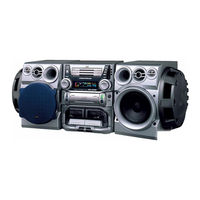
JVC MX-J750R Service Manual (133 pages)
Compact component system
Brand:
JVC
| Category:
CD Player
| Size: 17.62 MB
Table of Contents
Contents
1
Area Suffix
1
Each Difference Point
1
Safety Precautions
2
Warning
2
Important for Laser Products
3
Reproduction and Position of Labels
3
Warning Label
3
Preventing Static Electricity
4
Handling the Optical Pickup
4
Handling the Traverse Unit
4
Precautions at Disassembling and Parts Replacement
5
Instructions
6
Warnings and Cautions
6
Introduction
7
Precautions
7
Power Sources
7
Proper Ventilation
7
Location of the Buttons and Controls
8
Getting Started
8
Front Panel
8
Unpacking
8
Common Operations
9
Connecting Speakers
9
Connecting Other Equipment
9
Turning on or off the Power
9
Listening to FM and am Broadcasts
10
Receiving FM Stations with RDS
10
Tuning in a Station
10
Tuning in a Preset Station
10
Playing Back Cds
11
Loading Cds
11
Playing Back the Entire Discs
11
Playing Back Tapes
11
Recording
12
Using the Timers
12
Recording a Tape on Deck B
12
CD Direct Recording
12
Maintenance
13
Troubleshooting
13
Using Recording Timer
13
Using Sleep Timer
13
Additional Information
14
Specifications
14
Description of the PTY Codes
14
Connection
15
Disassembly Method
17
Main Body
17
Removing the Metal Cover
17
Removing the CD Changer Mechanism Assembly
18
Removing the Front Panel Assembly
19
Front Panel Assembly
20
Removing the Microphone Terminal Board Assembly
20
Removing the Rolling Panel Assembly
20
Removing the Main Board
21
Removing the Cassette Mechanism Assembly
21
Removing the Boards in the Front Panel Assembly
22
Function Board1
22
Function Board 2
22
Bass-Level Regulator Board
22
Removing the Relay Board and Fixing Board
23
Power Switch Board
23
Eject Switch Board
23
Remote Control Port Board
23
Rear Panel Assembly
24
Removing the Tuner Board
24
Removing the Input/Output Board
24
Removing the Rear Cover/Rear Panel
25
Removing the Pre-Amplifier Board/Heat Sink
26
Removing the Power & Main Amplifier Board
27
Rolling Panel Assembly
28
Removing the Multi-Control Assembly
28
Removing the Multi-Control Board
28
Removing the Drive Motor Assembly
29
Removing the CD Servo Control Board
30
Removing the CD Tray Assembly
30
Removing the CD Loading Mechanism Assembly
32
Removing the CD Traverse Mechanism
32
Removing the CD Pick Unit
32
Removing the Cam Unit
33
Removing the Actuator Motor and Belt
34
Assembly and Configuration Diagram
34
Removing the Cams R1/R2 Assembly and Cam Gear Q
35
Removing the C.G. Base Assembly
35
Cassette Mechanism Section
36
Removing the Playback, Recording and Eraser Heads
36
Reassembling the Playback, Recording and Eraser Heads
36
Removing the Head Amp. and Mechanism Control P.C. Board
37
Removing the Capstan Motor Assembly
37
Removing the Capstan Motor
38
Removing the Flywheel
38
Removing the Reel Pulse P.C. Board and Solenoid
38
Adjustment Method
39
Measurement Instruments Required
39
Measurement Conditions
39
Frequency Range
39
Arrangement of Adjusting Positions
40
Cassette Mechanism Section (Back Side)
40
Cassette Mechanism Unit Section
40
Tape Recorder Section
41
Reference Values
41
Electrical Performance
42
Reference Values for Electrical Function Confirmation Items
42
Diagnosis Which Uses Extension Wire Method
43
System Control P.C. Board
43
Extension Wire Parts
43
Flow of Functional Operation Unit TOC Read
44
Maintenance of Laser Pickup
45
Replacement of Laser Pickup
45
Description of Major Ics
46
Pin Layout
46
Block Diagram
46
Pin Function
47
4Channel Driver
48
Pin Layout & Block Diagram
48
MIC Mixer
49
OP Amp.
50
Serial to Parallel Port Extension
50
Receiver for Remote Controller
50
FM am if AMP& Detector, FM MPX Decoder
51
PLL Frequency Synthesizer
52
Control Volume
53
System Controller
54
Digital Servo & Digital Signal Processor
56
Terminal Layout
56
CD Changer Control
58
Lpf& Echo MIX
59
DC Motor Driver
60
Motor Driver
60
MIC Amplifier
60
Spi B.p.f.
61
RDS Demodulation
63
Main/Cassette/CD Section
65
Standard Schematic Diagrams
68
Power Transformer Section
68
Power Suppyl Block
68
Power Amplifier & Regulator Section
70
Function & Main Amplifier Section
72
FL Display & System Controller Section
74
Microphone Amplifier Section
76
CD Servo & Mechanism Control Section
78
Head Amplifier & Mechanism Control Section
80
Tuner Section
82
Printed Circuit Boards
86
Main & Preamplifier Board
86
Input/Output & Power Board
88
CD Tray Section Switch Board
90
Cam Switch Board
90
CD Servo Control Board
91
Cassette Mechanism Board
93
Tuner Board
94
Parts List
95
Exploded View of General Assembly and Parts List
98
CD Changer Mechanism Assembly and Parts List
104
Grease Point
109
Electrical Parts List
112
Packing Materials and Accessories Parts List
128
Related Products
JVC MX-J10
JVC MX-J700
JVC MC2000 - XL CD Changer
JVC MX-J70J
JVC MX-J70VU
JVC MX-J700C
JVC MX-J700J
JVC MX-J70
JVC MX-J770V
JVC MX-J270V
JVC Categories
Car Receiver
Camcorder
TV
VCR
Stereo System
More JVC Manuals