beautypg.com
Manuals
Brands
J&E Hall Manuals
Controller
Fridgewatch 2100
J&E Hall Fridgewatch 2100 Manuals
Manuals and User Guides for J&E Hall Fridgewatch 2100. We have
1
J&E Hall Fridgewatch 2100 manual available for free PDF download: Installation, Operating And Maintenance Manual
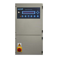
J&E Hall Fridgewatch 2100 Installation, Operating And Maintenance Manual (152 pages)
Controller Mk4
Brand:
J&E Hall
| Category:
Controller
| Size: 1.65 MB
Table of Contents
Safety
3
Table of Contents
4
About this Publication
9
Safety Warnings and Symbols
9
Units of Measurement
9
Terminology
9
Ordering Extra Copies
9
Care and Protection of Fridgewatch
10
Anti-Static Precautions
10
Electrical Interference
11
Prolonged Storage
11
Personnel Permitted to Install, Commission and Maintain Fridgewatch
11
General Description
12
Construction
13
Fig 1 Multiple Compressors with Common or Individual Oil Separator/Reservoirs
13
Technical Data
14
Table 1 Technical Data
14
Fig 2 Fridgewatch 2100 Mk4 Controller
15
Fig 3 Display Details
16
Fig 4 Internal Layout of Fridgewatch 2100 Panel
17
Fig 5 Enclosure Dimensions and Details of Cable Entries
19
Principles of Control
20
Compressor Capacity Control
20
Hallscrew 2000 Series Compressors
20
Hallscrew 2100 and 3100 Old Series Compressors
20
Hallscrew 3100 New Series, 3200 and 4200 Series Compressors
21
Fig 6 Slide Valve Position Switch Approximation of LVDT 4 to 20 Ma Signal
21
Proportional, Integral and Derivative (PID) Control
22
Proportional Band
22
Fig 7 Proportional, Integral and Derivative (PID) Control
23
Integral Action Time
24
Derivative Action Time
24
PID Control Set-Up
24
Basics of Starting and Stopping Compressors
25
Set Point Deviation
25
Master/Slave Operation
26
Starting the Master Compressor
26
Starting and Stopping the Slave Compressor
27
Master/Slave Operation with a Fridgewatch 2100 Controller Controlling more than One Compressor
27
Starting and Stopping the First Compressor
27
Compressor Running Order
28
Fig 8 Possible Compressor Start/Stop and Capacity Control Modes
29
Capacity Control by Fridgewatch 2100
30
Auto Capacity Control
30
Manual Capacity Control
30
Remote Capacity Control
30
Limiting Inputs
31
Control Strategy for Limiting Inputs
32
Current Limiting
32
Limiting on P4 Input
32
Fig 9 Limiting Inputs - Examples
34
Installation
35
Analogue Inputs for Sensing Start, Stop and Set Point Values
35
Using Two Start, Stop and Set Point Values
35
Table 2 Transducer Inputs
35
Digital Outputs
36
Installing Transducers
36
Using Fridgewatch 2100 to Drive Relays
36
Table 3 Rule for Selecting Controlling Parameters for Two Start Value/Set Point/Stop Value Sets
36
Fig 10 Transducer Installation
37
Power Supply Connections (Lower Half of Enclosure)
38
Panel Heater
38
Wiring Connections to DC Circuits (Upper Half of Enclosure)
38
Fig 11 Connecting Diodes
38
Opto-Electronic Liquid Sensor Interface Unit
39
Connections to Economiser Solenoid Valves
39
Wiring Connections to Electronic Cards
39
Jumper Connections on Electronic Cards
39
Table 4 Wiring Connections to Electronic Cards
39
Fig 12 Economiser Arrangements: Wiring to Liquid Line Solenoid Valves
40
Fridgewatch Highway Connections
41
Fig 13 Typical Fridgewatch Highway Connections
41
Summary of Master/Slave Connections
42
Fig 14 Wiring Connections for Master/Slave Without External Run Request or Run Enable Signal
43
Fig 15 Wiring Connections for Master/Slave with External Run Request or Run Enable Signal
44
Cards and Wiring Connections
45
FCPS1 Power Supply Card
45
Fig 16 FCPS1 Power Supply Card and Wiring Connections
45
3SCOP1 Relay Outputs Card
46
Fig 17 3SCOP1 Relay Outputs Card
46
Fig 18 Wiring Connections to 3SCOP1 Relay Outputs Card for Compressor 1
47
Fig 19 Wiring Connections to 3SCOP1 Relay Outputs Card for Compressors 2 and 3
48
Fig 20 RAMP4 Processor Card
49
Fig 21 ANP8 Display Card + Display
50
Fig 22 Wiring Connections to RAMP4 Processor Card
51
Fig 23 3MIO1 Input/Output Card for Compressor 1
52
Fig 24 Wiring Connections to 3MIO1 Input/Output Card for Compressor 1
53
Fig 25 3MIO2 Input/Output Card for Compressors 2 and 3
57
Fig 26 Wiring Connections to 3MIO2 Input/Output Card for Compressors 2 and 3
58
User Interface
62
Home Page
62
Event Codes
62
Fig 27 Menu Structure
63
Contents
64
Measured Points
64
Operator Settings and Configuration Settings
64
Mode Selection
64
Information
64
Status Indicators
65
Micro Ok
65
Trip
65
Operator Input Buttons
65
Acknowledge
65
Configuration Settings
66
Home Page
66
Previous Menu
66
Stop Compressor(S) (All Modes)
66
Enter
66
Scroll up - Raise Setting - Start/Load Compressor (Manual Control Only)
67
Lower Setting - Unload Compressor (Manual Control Only)
68
Supervisor Keyswitch
68
Commissioning
70
Authority to Use the Supervisor Key
70
Checks to be Made Prior to Supplying Power to Fridgewatch 2000
70
Transducer Calibration and Potentiometer Adjustment
71
Inputting Configuration and Operator Settings During Commissioning, Operating Mode for the First Start
71
Inputting Configuration Settings During Commissioning
71
Fig 28 Looking at or Changing Configuration Settings
72
Inputting Operator Settings During Commissioning
74
Operating Mode for the First Start
74
Changing Operator Settings after Commissioning
74
Changing Configuration Settings after Commissioning
74
Fig 29 Looking at or Changing Operator Settings
75
Changing the Operating Mode
76
Checking the Software Version Number
76
Printing or Downloading the Settings List
77
Fig 30 Changing the Operating Mode
77
Event Codes
78
Information Only Events
78
Trip Events
78
Compressor Healthy 'Off
78
Fig 31 Identifying and Clearing Trip Events, Reasons for Normal Stop and Reason for Trip
79
Event Codes Description
80
Table 5 E14 High or Low P6 (Pressure or Temperature)
83
Settings
87
Operator Settings S1/S39
87
Table 6 Determining Compressor Running Order Priority
88
Table 7 Run Enable Required in Different Operating Modes - Values for S14
91
Table 8 Operating Mode Indication Using Setting S19
92
Fig 32 Flowchart to Assist in Adjusting Start Value/Set Point/Stop Value Times
94
Table 9 Initial Load Values on Starting
96
Configuration Settings S41/109
98
Table 10 Transducer/Transmitter Types and Ranges
99
Table 11 Swept Volumes of Hallscrew Compressors
101
Table 12 Capacity Control Valve Application and Operation
104
Table 13 Slide Valve Position Indication for Hallscrew Compressors
105
Table 14 Slide Valve Position Options - Values for S63
106
Table 15 Values for S75 to S80 Current Date and Time
109
Maintenance
122
Calibration of Pressure Transducers
122
Calibration of Temperature Transducers
123
Calibration of Motor Current
124
Calibration of LVDT 4 to 20 Ma Signal - HS 2000 Series Compressors
125
Calibration of LVDT 4 to 20 Ma Signal - HS 3100 New Series, HS 3200 and HS 4200 Series Compressors
125
Fitting a New RAMP4 Processor Card
125
Fig 33 Calibration of LVDT 4 to 20 Ma Signal - HS 3100 New Series, HS 3200 and HS 4200 Series Compressors
126
Checking and Replacement of Lithium Back-Up Battery
128
Maintenance Check List
128
Table 16 Maintenance Check List
128
Spares
129
Fuses for Mains Input
129
Electronic Card Compatibility
129
Table 17 Fuses
129
Table 18 Electronic Cards
129
Appendix 1 - Measured Points Reference
130
Table 19 Measured Points Quick-Reference
130
Table 20 Measured Points Function and Settings Cross-Reference
130
Appendix 2 - Event Codes E1/E47 Quick-Reference
131
Appendix 3 - Settings Record
133
Compressor Number/Compressor Serial Number Record
133
Table 21 Compressor Number/Compressor Serial Number Record
133
Appendix 4 - Start-Up Timing Diagram
148
Fig 34 Compressor Start-Up Timing Diagram
148
Index
150
Related Products
J&E Hall Fridgewatch 2000
J&E Hall Fridgewatch 4000
J&E Hall Categories
Heat Pump
Accessories
Controller
Freezer
Transmitter
More J&E Hall Manuals