beautypg.com
Manuals
Brands
HP Manuals
Server
A9834-9001B
HP A9834-9001B Manuals
Manuals and User Guides for HP A9834-9001B. We have
1
HP A9834-9001B manual available for free PDF download: User's & Service Manual
HP A9834-9001B User's & Service Manual (247 pages)
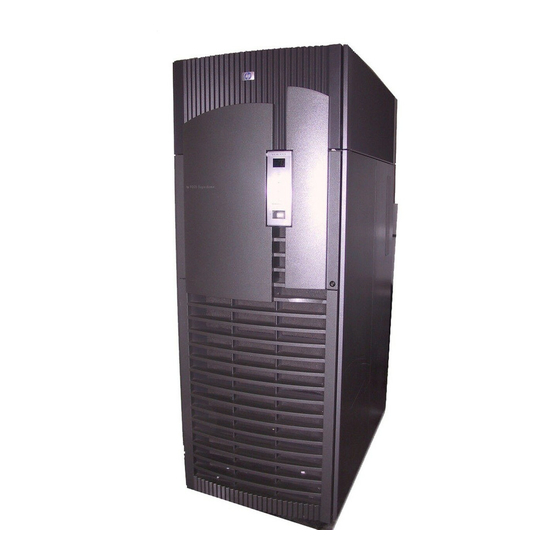
Hewlett-Packard Integrity Superdome Server User Service Guide
Brand:
HP
| Category:
Server
| Size: 6.17 MB
Table of Contents
Legal Notices
2
Table of Contents
3
About this Document
15
Intended Audience
16
Typographic Conventions
17
Related Information
18
Publishing History
19
Hp Encourages Your Comments
20
1 Overview
21
Server History and Specifications
23
Server Components
24
Figure 1-1 Superdome Cabinet
25
Power System
26
AC Power
26
DC Power
27
System Power on Sequence
27
Enabling 48 Volts
27
Cooling System
28
Utilities Subsystem
30
Platform Management
30
IPF Firmware
30
Uguy
31
CLU Functionality
31
Figure 1-2 UGUY
31
PM3 Functionality
32
System Clocks
32
Managemant Processor (SBCH and SBC)
32
Compact Flash
33
Figure 1-3 Management Processor
33
Hucb
34
Figure 1-4 HUCB
34
Backplane (Fabric)
35
Crossbar Chip - XBC
35
Switch Fabrics
35
Backplane Monitor and Control
36
I2C Bus Distribution
36
Clock Subsystem
36
Table 1-1. HSO LED Status Indicator Meaning
37
Figure 1-5 Locations of HSO and RCS
38
Cabinet ID
39
Cell ID
39
Backplane Power Requirements and Power Distribution
39
Figure 1-6 Backplane Power Supply Module
40
Figure 1-7 Backplane (Rear View)
40
Cpus and Memories
41
Cell Controller
41
Figure 1-8 Cell Board
41
Processor Interface
42
Processors
42
Cell Memory System
42
Table 1-2 Supported Processors and Minimum Firmware Version Required
42
Figure 1-9 Cell Memory
43
PDC Functional Changes
46
Platform Dependant Hardware
47
Reset
47
Cell OL
47
I/O Subsystem
48
PCI-X Backplane Functionality
48
Figure 1-10 I/O Rope Mapping
49
New Server Cabling
52
M-Link Cable
52
E-Link Cable
52
Figure 1-11 Backplane Cables
53
Firmware
54
Server Configurations
55
Server Errors
56
Protection Domain Access Errors
56
Hardware Corrected Errors
56
Global Shared Memory Errrors
56
Hardware Uncorrectable Errors
57
Fatal Errors
57
Blocking Timeout Fatal Errors
57
Deadlock Recovery Reset Errors
57
Error Logging
57
2 System Specifications
59
Dimensions and Weights
60
Component Dimensions
60
Table 2-1. Server Component Dimensions
60
Table 2-2. I/O Expansion Cabinet Component Dimensions
60
Component Weights
61
Table 2-3 System Component Weights
61
Table 2-4 I/O Expansion Cabinet Weights
61
Shipping Dimensions and Weights
62
Table 2-5. Miscellaneous Dimensions and Weights
62
Electrical Specifications
63
Grounding
63
Circuit Breaker
63
Power Options
63
Table 2-6. Available Power Options
63
Table 2-7. Option 6 and 7 Specifics
64
System Power Requirements
65
Figure 2-1. PDCA Locations
65
Component Power Requirements
66
I/O Expansion Cabinet Power Requirements
66
Table 2-8 Power Requirements (Without Support Management Station)
66
Table 2-9 Component Power Requirements (Without Support Management Station)
66
I/O Expansion Cabinet Power Cords
67
Table 2-10. I/O Expansion Cabinet Power Requirements (Without Support Management Station) 67 Table 2-11. I/O Expansion Cabinet Component Power Requirements
67
Table 2-12. I/O Expansion Cabinet Ac Power Cords
67
Environmental Requirements
68
Temperature and Humidity Specifications
68
Power Dissipation
68
Table 2-13. Operational Physical Environment Requirements
68
Table 2-14. Nonoperational Physical Environment Requirements
68
Table 2-15. Typical HP Integrity Superdome/Sx2000 for Dual-Core CPU Configurations
69
Table 2-16. Typical HP Integrity Superdome/Sx2000 for Single-Core CPU Configurations
70
Acoustic Noise Specification
72
Airflow
73
Figure 2-2. Airflow Diagram
73
Table 2-17. Physical Environmental Specifications
74
3 Installing the System
75
Introduction
76
Communications Interference
76
Electrostatic Discharge
76
Public Telecommunications Network Connection
76
Unpacking and Inspecting the System
77
Verifying Site Preparation
77
Checking the Inventory
77
Inspecting the Shipping Containers for Damage
78
Figure 3-1 Normal Tilt Indicator
79
Figure 3-2 Abnormal Tilt Indicator
79
Unpacking and Inspecting Hardware Components
80
Figure 3-3 Front of Cabinet Container
81
Figure 3-4 Cutting Polystrap Bands
82
Figure 3-5 Removing the Ramps from the Pallet
83
Figure 3-6 Location of Power Supply Mounting Screws
84
Figure 3-7 I/O Chassis Mounting Screws
85
Figure 3-8 Shipping Strap Location
86
Figure 3-9 Removing the Mounting Brackets
86
Figure 3-10 Positioning the Ramps
87
Unpacking the PDCA
88
Figure 3-11 Rolling the Cabinet down the Ramp
88
Returning Equipment
89
Table 3-1 Available Power Options
89
Table 3-2 Power Cord Option 6 and 7 Specifics
89
Setting up the System
91
Moving the System and Related Equipment to the Installation Site
91
Unpacking and Installing the Blower Housings and Blowers
91
Figure 3-12 Blower Housing Frame
91
Figure 3-13 Removing Protective Cardboard from the Housing
92
Figure 3-14 Installing the Rear Blower Housing
92
Figure 3-15 Installing the Front Blower Housing
93
Figure 3-16 Installing the Blowers
93
Attaching the Side Skins and Blower Side Bezels
94
Figure 3-17 Attaching the Rear Side Skin
94
Figure 3-18 Attaching the Front Side Skins
95
Figure 3-19 Attaching the Side Bezels
96
Attaching the Leveling Feet and Leveling the Cabinet
97
Installing the Front Door Bezels and the Front and Rear Blower Bezels
97
Figure 3-20 Attaching the Leveling Feet
97
Figure 3-21 Installing the Lower Front Door Assembly
98
Figure 3-22 Installing the Upper Front Door Assembly
99
Figure 3-23 Installing the Rear Blower Bezel
100
Wiring Check
101
Figure 3-24 Installing the Front Blower Bezel
101
Installing and Verifying the PDCA
103
Figure 3-25. PDCA Assembly for Options 6 and 7
104
Figure 3-26 a 4-Wire Connector
104
Figure 3-27 a 5-Wire Connector
105
Figure 3-28 Installing the PDCA
106
Table 3-3. 4- and 5-Wire Voltage Ranges
107
Figure 3-29. Checking PDCA Test Points (5-Wire)
107
Voltage Check
108
Figure 3-30 Wall Receptacle Pinouts
108
Figure 3-31 Power Supply Indicator LED Detail
109
Removing the EMI Panels
110
Figure 3-32 Removing Front EMI Panel Screw
110
Connecting the Cables
111
Figure 3-33 Removing the Back EMI Panel
111
Routing the I/O Cables
112
Figure 3-34 Cable Labeling
112
Figure 3-35 Routing I/O Cables
113
Installing the Support Management Station
115
Configuring the Event Information Tools
116
Turning on Housekeeping Power
117
Figure 3-36 Front Panel with Housekeeping (HKP) Power on and Present Leds
118
Figure 3-37 BPS Leds
119
Connecting the MP to the Customer LAN
120
Connecting the MP to the Network
120
Figure 3-38 MP LAN Connection Location
120
Setting the Customer IP Address
121
Figure 3-39 LAN Configuration Screen
121
Figure 3-40 the Ls Command Screen
122
Booting and Verifying the System
123
Connecting to the Management Processor
123
Figure 3-41 Connecting to Host
123
Figure 3-42 Main MP Menu
124
Figure 3-43 MP Command Option
124
Figure 3-44 MP Virtual Front Panel
125
Figure 3-45 Example of Partition State-Cabinet Not Powered up
125
Powering on the System 48 V Supply
126
Figure 3-46 MP Console Option
126
Booting the HP Integrity Superdome/Sx2000 to a EFI Shell
127
Figure 3-47 HP Integrity Superdome/Sx2000 EFI Boot Manager
127
Figure 3-48 EFI Shell Prompt
128
Verifying the System
129
Figure 3-49 HP Integrity Superdome/Sx2000 Partitions at System Firmware Console
129
Figure 3-50 Power Status First Window
129
Figure 3-51 Power Status Window
130
Figure 3-52 Power Status Showing State of UGUY Leds (and Other Status)
130
Running JET Software
132
Running JUST
132
Power Cycling after Using JET
132
Offline Diagnostic Environment (ODE)
133
Attaching the Rear Kick Plates
134
Figure 3-53 Attaching Rear Kick Plates
134
Performing a Visual Inspection and Completing the Installation
135
Figure 3-54 Cell Board Ejectors
135
Figure 3-55 Front EMI Panel Flange and Cabinet Holes
136
Figure 3-56 Reinstalling the Back EMI Panel
137
Conducting a Post Installation Check
138
4 Booting and Shutting down the Operating System
139
Operating Systems Supported on Cell-Based HP Servers
140
System Boot Configuration Options
141
HP Integrity Boot Configuration Options
141
Booting and Shutting down HP-UX
145
HP-UX Support for Cell Local Memory
145
Adding HP-UX to the Boot Options List
145
Booting HP-UX
146
Shutting down HP-UX
151
Booting and Shutting down HP Openvms I64
153
HP Openvms I64 Support for Cell Local Memory
153
Adding HP Openvms to the Boot Options List
153
Booting HP Openvms
155
Shutting down HP Openvms
156
Booting and Shutting down Microsoft Windows
158
Microsoft Windows Support for Cell Local Memory
158
Adding Microsoft Windows to the Boot Options List
158
Booting Microsoft Windows
160
Shutting down Microsoft Windows
161
Booting and Shutting down Linux
163
Linux Support for Cell Local Memory
163
Adding Linux to the Boot Options List
163
Booting Red hat Enterprise Linux
165
Booting Suse Linux Enterprise Server
166
Shutting down Linux
167
Sx2000 Leds
169
Table A-1 Front Panel Leds
170
Table A-2. Power and OL* Leds
171
Figure A-1 Utilities Leds
172
Table A-3. OL* LED States
172
Table A-4 PDH Status and Power Good LED States
173
Figure A-2. PDH Status
173
Management Processor Commands
175
MP Command: BO
176
MP Command: CA
177
MP Command: CC
178
MP Command: CP
179
MP Command: DATE
180
MP Command: DC
181
MP Command: DF
182
MP Command: DI
183
MP Command: DL
184
MP Command: el
185
MP Command: HE
186
MP Command: ID
188
MP Command: IO
189
MP Command: IT
190
MP Command: LC
191
MP Command: LS
192
MP Command: MA
193
MP Command: ND
194
MP Command: PD
195
MP Command: PE
196
MP Command: PS
198
MP Command: RE
200
MP Command: RL
201
MP Command: RR
202
MP Command: RS
203
MP Command: SA
204
MP Command: so
205
MP Command: SYSREV
206
MP Command: TC
207
MP Command: te
208
MP Command: VM
209
MP Command: WHO
210
MP Command: XD
211
Powering the System on and off
213
Shutting down the System
214
Checking System Configuration
214
Figure C-1 Connecting to Host
214
Figure C-2 Main MP Menu
215
Figure C-3 Checking for Other Users
215
Figure C-4 Checking Current System Configuration
216
Figure C-5 MP Virtual Front Panel
216
Shutting down the Operating System
217
Figure C-6 Example of Partition State
217
Figure C-7 Partition Consoles Menu
217
Preparing the Partitions for Shutdown
218
Figure C-8 Issuing an Rr Command
218
Powering off the System Using the Pe Command
219
Figure C-9 Using the de -S Command
219
Figure C-10 Power Entity Command
220
Figure C-11 Power Status First Window
220
Figure C-12 Power Status Second Window
221
Turning on Housekeeping Power
222
Figure C-13 Front Panel Display with Housekeeping (HKP) Power On, and Present Leds
223
Figure C-14 BPS Leds
224
Powering on the System Using the Pe Command
225
Figure C-15 Power Entity Command
225
Figure C-16 Power Status First Window
226
Figure C-17 Power Status Window
226
Templates
227
Templates
228
Figure D-1 Cable Cutouts and Caster Locations
229
Figure D-2 SD16 and SD32 Space Requirements
230
Equipment Footprint Templates
231
Figure D-3 SD64 Space Requirements
231
Computer Room Layout Plan
232
Figure D-4 Computer Floor Template
233
Figure D-5 Computer Floor Template
234
Figure D-6 Computer Floor Template
235
Figure D-7 Computer Floor Template
236
Figure D-8 Computer Floor Template
237
Figure D-9 SD32 and SD64, and I/O Expansion Cabinet Templates
238
Figure D-10 SD32 and SD64, and I/O Expansion Cabinet Templates
239
Figure D-11 SD32 and SD64, and I/O Expansion Cabinet Templates
240
Figure D-12 SD32 and SD64, and I/O Expansion Cabinet Templates
241
Figure D-13 SD32 and SD64, and I/O Expansion Cabinet Templates
242
Figure D-14 SD32 and SD64, and I/O Expansion Cabinet Templates
243
Index
245
Related Products
HP AX691B
HP AJ732A - Cisco MDS 9134 Fabric Switch
HP AA979A - StorageWorks SAN Switch 2/8V
HP AP775A - Nexus Converged Network Switch 5010
HP AP776A - Nexus Converged Network Switch 5020
HP AB464-9003F
HP Apollo 2000 System
HP Server Automation
HP NetServer AA 4000
HP NetServer AA 6200
HP Categories
Desktop
Laptop
Server
Monitor
Switch
More HP Manuals