beautypg.com
Manuals
Brands
HP Manuals
Measuring Instruments
3585A
HP 3585A Manuals
Manuals and User Guides for HP 3585A. We have
2
HP 3585A manuals available for free PDF download: Service Manual, Operating Manual
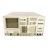
HP 3585A Service Manual (277 pages)
SPECTRUM ANALYZER
Brand:
HP
| Category:
Measuring Instruments
| Size: 18.38 MB
Table of Contents
Table of Contents
3
Service Manual
1
Section Page
5
General Information
11
1 · 1 . I Ntroduction
11
Specifications
11
Instrument and Manual Identification
11
Description
12
Options
13
1-7. Accessories Available
14
Recommended Test Equipment
15
Installation and Interfacing
21
Introduction
21
Initial Inspection
21
Power Requirements
21
Grounding Requirements
21
Environmental Requirements
21
Operating Environment
22
Power Cables
22
Bench Mounting
23
Installation
23
Thermal Cutout
23
Storage and Shipping Environment
23
Cooling System
23
Rack Mounting Without Slides
24
Rack Mounting with Slides
25
Instrument Turn on
26
Front-Panel Functions Activated at Turn -On
27
Turn-On Display
28
HP-IB Connections and Interfacing
29
Cable Length Restrictions
29
Calculator Interfacing
30
HP-IB Address Selection
30
Other Packaging
32
Repackaging for Shipment
32
Original Packaging
32
Operation Overview
33
Performance Summary and Description
34
Turn on and Warmup
35
Frequency Reference
35
Internal Oven Reference
35
External Reference
36
Operational Verification
36
Front Panel Features
37
Rear-Panel Features
55
Performance Tests
60
Introduction
60
Calibration Cycle
60
Performance Test Record
60
Recommended Test Equipment
60
IV. Per Formance Tests
60
Operational Verification Tests Overview
62
4-7. Operational Verification Tests
63
Frequency Accuracy
64
Calibrator Test (Optional)
65
M Ohm Input Impedance Test
75
Intermodulation Distortion Test
84
IM Distortion Response
86
Table of Contents
90
Semi-Automatic Performance Tests
94
Automatic Performance Testing
95
M Ohm Input Impedance Test
98
Equipment Set-Up
99
Equ.ipment Set-Up
100
For Calibration Data
101
Intermodulation Distortion Test
104
Semi-Automatic Performance Test Procedure
105
Cal Offset Test
109
Range Calibration
109
Amplitude Linearity Test
110
Reference Level Accuracy
110
Marker Accuracy
111
Return Loss Tests
111
Low Frequency Responses
112
Noise
112
Zero Response
112
Bandwidth Tests
114
Fractional N API Spur Test
114
Tracking Generator Flatness Test
114
5- 1 . Introduction
115
Adjustments
115
CRT Control and High Voltage
115
Locations
115
CRT Control and High Voltage Power Supply Adjustments
123
CRT Graphics Adjustment
129
CRT Alphanumeric Alignment
133
Fractional N Adjustments
138
Step Loop Adjustments
138
First L.O. VTO and Sum Loop Adjustments
140
Video Filter and A/D Converter Adjustments
142
Log Amp and 30Khz Filter Adjustments
144
Db/DIV
146
Adjustment
148
Instrument Preset
146
Log Amp Slope Adjustment
146
Recall 601
146
Set the 3585A Controls for
146
A. Set the 35 85A Controls for
149
Db/DIV
149
Instrument Preset
149
Range
149
Reference Level
149
Reference Level DC Offset Adjustment
149
Filter Adjustments
150
Fourth Crystal Stage Adjustment
154
Fourth LC Stage Adjustment
155
Offset
155
Fifth LC Stage Adjustment
156
Third Crystal Stage Adjustment
156
Second Crystal Stage Adjustment
158
First Crystal Stage Adjustment
159
Second LC Stage Adjustment
159
Enter Offset
160
16Db Amplifier Adjustment
162
Conversion Section Adjustments
166
Calibrator Symmetry Adjustment
171
Input Section
171
Flatness Adjustment
173
Range down Detector Adjustment
176
Range up Detector Adjustment
176
Calibrator Level Adjustment
177
Top of Screen Amplitude Adjustment
177
1MO Amplitude Adjustment
178
MO Flatness Adjustment
178
1MO Input Capacitance Adjustment
179
Electrical Isolation Test
181
Local Oscillator Feedthrough Adjustment
181
HP-IB Adjustment
182
5-48. X-Y Plotter Adjustment
183
Circuit Functional Descriptions
186
Circuitry Overview
186
Introduction
186
Display (SG-D)
187
Counter (SG-G)
188
Power Supplies (SG-I)
188
X-Y Plotter (SG-H)
188
Conversion (A2 Thru A5)
189
IF (A17 Thru A19)
189
Input (Al)
189
Log Amplifier (A14)
189
RF/IF Description (Service Group A)
189
Video Filter (A15)
189
6-1B. A/D Converter (A16)
193
Local Oscillator Description (Service Group B)
197
Step Loop (A23 and A26)
197
Sum Loop
197
Fractional N Loop (A31, A32 and A33)
205
LO Control (A34)
206
Processor Description (Service Group C)
210
Display Description (Service Group D)
214
Tracking Generator Description (Service Group E)
219
Counter Description (Service Group G)
223
X-Y Plotter Description (Service Group H)
224
Power Supply Description (Service Group I)
225
Backdating
230
Introduction
230
A-13: L7 and C31) ........ '"
234
Table of Contents
236
Db/DIV
237
Frequency Span
237
Second Crystal Stage Adjustment
237
First Crystal Stage Adjustment
238
Second LC Stage Adjustment
239
Adjust a 1 3 R20 for a .Oodb Marker Amplitude
240
Cf Step Size
240
Adjustment
240
Place Jumper a 1 3 J4 to the "OP" Position
240
Set the -Hp- 3585A to
240
Adjustment
241
Res Bw
241
Db/DIV
242
Frequency Span
242
Set the -Hp- 3585A to
242
Applicable Serial Number
265
Affected Manual Areas
267
Applicable Serial Numbers
267
L 4 -Crystal Replacement Procedure
273
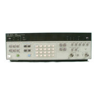
HP 3585A Operating Manual (214 pages)
Synthesizer/Function Generator Operating Manual
Brand:
HP
| Category:
Synthesizer
| Size: 7.19 MB
Related Products
HP 3575A
HP 3561a
HP 3562A
HP 3580A
HP 3456A
HP 3455A
hp 3406A
HP 37719A
HP 3437A
HP Agilent 37717B PDH
HP Categories
Desktop
Laptop
Server
Monitor
Switch
More HP Manuals