beautypg.com
Manuals
Brands
Honeywell Manuals
Control Panel
Notifier RP-2001E
Honeywell Notifier RP-2001E Manuals
Manuals and User Guides for Honeywell Notifier RP-2001E. We have
1
Honeywell Notifier RP-2001E manual available for free PDF download: Instruction Manual
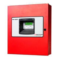
Honeywell Notifier RP-2001E Instruction Manual (132 pages)
Pre-Action/Deluge Control Panel
Brand:
Honeywell
| Category:
Control Panel
| Size: 2.38 MB
Table of Contents
Table of Contents
5
Section 1: Product Description
12
Product Features
12
Specifications
13
Controls and Indicators
16
Components
17
Optional Modules and Accessories
17
Section 2: Installation
19
Backbox Mounting
19
Operating Power
22
Input Circuits
24
Output Circuits
26
1: Outputs/Notification Appliance/Releasing Circuits
26
2: Special Application DC Power Output Connections
27
3: Relays - Programmable
27
Power-Limited Wiring Requirements
28
Installation of Optional Modules
29
1: N-CAC-5X Class a Converter Module
29
Installation
29
Wiring Nacs and Idcs for Class a
30
2: 4XTM Municipal Box Transmitter Option Module
31
4XTM Transmitter Module Installation
31
3: ANN-SEC Option Card
33
ANN-BUS Devices
33
Guidelines
33
1: ANN-BUS Wiring
34
Calculating Wiring Distance for ANN-BUS Modules
34
Wiring Configuration
36
Powering ANN-BUS Devices from Auxiliary Power Supply
36
2: ANN-BUS Device Addressing
37
3: N-ANN-80 Remote LCD Annunciator
37
Specifications
37
Installation
37
Wiring N-ANN-80 to FACP
38
4: N-ANN-S/PG Serial/Parallel Printer Interface Installation
39
Specifications
40
Printer Installation
40
Printer Installation
41
5: N-ANN-I/O LED Driver Module
42
N-ANN-I/O Board Layout
43
Specifications
43
N-ANN-I/O Connection to FACP
44
N-ANN-I/O Module LED Wiring
44
6: N-ANN-LED Annunciator Module
45
Specifications
45
Mounting/Installation
45
N-ANN-LED Board Layout and Connection to FACP
46
7: N-ANN-RLY Relay Module
46
Specifications
46
Mounting/Installation
47
N-ANN-RLY Board Layout and Connection to FACP
47
Section 3: Programming
48
User Programming
48
Initial Power-Up
49
Programming Screens Description
49
Programming and Passwords
50
Master Programming Level
51
1: FACP CONFIG (Application Templates)
51
2: Input Zones
52
3=Output Circuits
56
Enabled
56
Type
56
Silence
57
Auto Silence
58
Silence Inhibited
58
Coding
58
4: Cross Input Zones
60
5: On-Board Relays
60
6: System Setup
61
Timers
62
Banner
63
Time-Date
64
Trouble Reminder
65
Charger Disable
65
Canadian Option
66
Secondary ANN-BUS Option
66
7: Ann-Bus
66
ANN-BUS Enabled
66
ANN-BUS Modules
67
Auto-Configure
67
ANN-S/PG Options
67
ANN-I/O LED Zone Assignments
68
Options
69
ANN-RLY Options
69
8: History
70
View Events
70
Erase History
71
9: Walktest
71
10: Clear Program
72
11: Password Change
72
Maintenance Programming Level
72
1: Input Zones - Enable/Disable
73
2=History
73
3: Walktest
74
4: Time-Date
74
Section 4: Operating Instructions
76
Panel Control Buttons
76
1: Acknowledge/Step
76
2: Alarm Silenced (Domestic/Export Versions)/Signal Silence (Canadian Version)
76
3: Drill/Hold 2 Sec (Domestic/Export Versions)/Alarm Signal (Canadian Version)
76
4: Reset
76
Indicators
77
Normal Operation
77
Trouble Operation
78
Alarm Operation
79
Supervisory Operation
80
Disable/Enable Operation
80
Waterflow Circuits Operation
80
2Nd-Shot Water Switch
81
Detector Functions
81
Coded NAC Operation
81
Release Stages
81
Special System Timers
82
1: Silence Inhibit Timer
82
2: Autosilence Timer
82
3: Trouble Reminder
82
4: Soak Timers
82
5: Waterflow Delay Timer
82
Walktest
82
Read Status
83
1: FACP Configuration
83
2=Input Zones
84
3=Output Circuits
84
4: Cross Input Zones
84
5: On-Board Relays
85
6: System Settings
85
7: Timers
85
8: Daylight Savings
85
9: History
86
10: Print
86
11: Ann-Bus
86
Section 5: Power Supply Calculations
87
Overview
87
Calculating the AC Branch Circuit
87
Calculating the System Current Draw
88
1: Overview
88
2: How to Use Table 5.3 on Page 89 to Calculate System Current Draw
88
Calculating the Battery Size
90
1: NFPA Battery Requirements
90
2: Selecting and Locating Batteries
90
Appendix A: Circuit Mapping and Cross-Zoning
91
A.1: Input-To-Output Circuit Mapping and Cross-Zone Operation
91
A.1.1: Mapping Input Zones to Output Circuits for Direct Activation
92
A.1.2: Mapping Input Zones to Release Circuits for Cross Zone Activation
93
A.1.3: Complex Examples of Cross Zoning and I/O Mapping for Release Circuits
95
Appendix B: FACP Configuration Templates
96
B.1: Template 1: Single Hazard - 3 Zone
97
B.2: Template 2: Single Hazard - Cross-Zone with Manual Release
99
B.3: Template 3: Dual Hazard - Combined Release
101
B.4: Template 4: Dual Hazard - Split Release
103
B.5: Template 5: Single Hazard - 3 Zones and Low Pressure
105
B.6: Template 6: Single Hazard - 2 Zones Cross-Zoned with All Active
107
B.7: Template 7: Single Hazard - Dual Zone
109
Appendix C: NFPA Standard-Specific Requirements
111
C.1: NFPA 72 Auxiliary Fire Alarm System
114
C.2: Central Station/Remote Station Transmitter: Connection to FACP Dry Contacts
117
Appendix D: FACP with Keltron
118
Appendix E: Testing & Maintenance
119
E.1: Testing
119
E.1.1: Inspection
119
E.1.2: Alarm Test
119
E.1.3: Detector Testing
119
E.2: Maintenance
120
Appendix F: Wire Requirements
121
F.1: NAC Wiring
122
Index
123
Rp-2001, Rp-2001E, Rp-2001C
129
Pre-Action/Deluge Control Panel
129
Operating Instructions
129
Related Products
Honeywell Notifier RP-2001
Honeywell Notifier RP-2001C
Honeywell NOTIFIER RP-2002C
Honeywell NOTIFIER RP1r
Honeywell Notifier ID50
Honeywell Notifier ID60
Honeywell Notifier ID3000 Series
Honeywell Notifier NFS-320
Honeywell Notifier NFS-320SYS
Honeywell Notifier ST.PL4+
Honeywell Categories
Thermostat
Controller
Control Unit
Security Camera
Accessories
More Honeywell Manuals