beautypg.com
Manuals
Brands
Honeywell Manuals
Controller
HercuLine 2000 Series
Honeywell HercuLine 2000 Series Manuals
Manuals and User Guides for Honeywell HercuLine 2000 Series. We have
2
Honeywell HercuLine 2000 Series manuals available for free PDF download: Installation, Operation And Maintenance Manual, Quick Start Manual
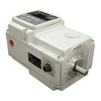
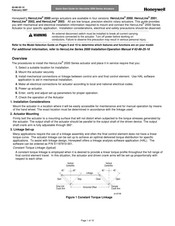
Honeywell HercuLine 2000 Series Installation, Operation And Maintenance Manual (128 pages)
Brand:
Honeywell
| Category:
Controller
| Size: 3.44 MB
Table of Contents
Table of Contents
5
Introduction
9
Product Description
9
Figure 2 Herculine ® 2002 Actuator Internal View
11
Specifications
13
Technical and Operating Specifications
13
Table 1 Specifications - General
13
Model Selection Guide
18
Installation
20
Installation Overview
20
Mechanical Stops
20
Before Starting
21
Actuator Mounting
21
Figure 3 Outline and Dimensions of Herculine
22
Mechanical Installation
23
Figure 4 Constant Torque Linkage
23
Figure 5 Variable Torque Linkage
24
Figure 6 Standard Crank Arm
24
Figure 7 Crank Arm with Optional Ball Joint and Push Rod
24
Electrical Installation
25
Table 2 Recommended Minimum Wire Size
25
Table 3 Terminal Connections: Herculine ® 2000
26
Table 4 Terminal Connections: Herculine
26
Figure 1 Herculine ® 2000 Series Actuator
26
Figure 2 Herculine
26
Figure 10 Herculine ® 2003 Connections
28
Figure 11 CE Wiring Part 1
29
Figure 12 CE Wiring Part 2
30
Burner Control/Flame Safety
31
Figure 13 Burner Control/Flame Safety Wiring
31
Series 90 Control - Herculine® 2001 Model Only
32
Figure 14 Series 90 Connections
32
Figure 15 T775 Controller Connections
33
Split Range
34
Master/Slave Arrangement
34
Table 5 Split Range Set up Procedure
34
Figure 16 Flow Diagram
35
Figure 17 Interconnection Diagram
35
Figure 18 Proportional Flow Using Multiple Actuators
36
Figure 19 Multiple Actuator Interconnection Diagrams
37
Figure 20 Interconnection Diagrams
38
Set up and Calibration Procedures
39
Overview
39
Local Display and Keypad
39
Figure 21 Herculine ® 2000 Display and Keypad
39
Table 6 Keypad Description
40
Set up Tips
41
Table 7 Set up Tips
41
Set up Groups
42
Table 8 Set up Groups
42
Set up Procedure
44
Table 9 Set up Procedure Using Display and Keypad
44
Configuration Prompt Hierarchy
46
Input Set up Group
47
Table 10 Input Set up Group Parameters
47
Table 11 Equal Percentage Valve Characteristics
50
Table 12 Quick Opening Valve Characteristic
51
Relays Set up Group
52
Table 13 Relay Set up Group Parameters
52
Table 14 Relay Type Descriptions
53
Figure 22 Relay Connectors
54
Current out Set up Group
57
Table 15 Current out Set up Group Parameters
57
Communications Set up Group
58
Table 16 Communications Set up Group Parameters
58
Digital Input Set up Group
59
Table 17 Digital Input Set up Group Parameters
59
Display Set up Group
60
Table 18 Display Set up Group Parameters
60
Lock Set up Group
61
Table 19 Lock Set up Group Parameters
61
Read Status Set up Group
63
Table 20 Read Status Set up Group Parameters
63
Drive Set up Group
64
Table 21 Drive Set up Group Parameters
64
Maintenance Set up Group
67
Table 22 Maintenance Set up Group Parameters
67
Regions of Motor Travel
70
Figure 23 Regions of Motor Travel
70
CAL POSOUT Group
71
Table 23 CAL POSOUT Group Parameters
71
Auto - Manual Drive Switch
72
Table 24 Auto - Manual Switch Functions
72
Figure 24 Auto - Manual Switch
72
Calibration
73
Figure 25 Calibration Wiring Connections (Non-Slidewire Emulation)
74
Figure 26 Calibration Wiring Connections (Slidewire Emulation)
75
Figure 27 Jumper Location on CPU PWA
76
Table 25 Input Calibration Procedure
77
Table 26 Motor Calibration Procedure
78
Table 27 Output Calibration Procedure
79
Table 28 Slidewire Emulation Calibration Procedure
81
Table 29 NCS Position Sensor Calibration Procedure
82
Figure 28 Location of NCS Assembly
83
Table 30 Potentiometer Position Sensor Calibration Procedure
84
Table 31 Load Position Sensor Factory Calibration
85
Figure 29 Location of Potentiometer Position Sensor
85
Setting End-Of-Travel Limit Switches
86
Figure 30 End of Travel Limit Switch Settings
86
Table 32 End-Of-Travel Limit Switch Setting Procedure
87
Figure 31 Location of End-Of-Travel Limit and Auxiliary Switches
88
Setting Auxiliary Switches
89
Figure 32 Auxiliary Switch Settings
89
Table 33 Auxiliary Switch Setting Procedure
90
Start-Up/Operation
91
Introduction
91
Power-Up Diagnostics
91
Operations Checklist
91
Operating Displays
92
Motor Stall
92
Table 34 Typical Operating Displays
92
Position Sensor Operation
93
Remote Setpoint Operation
93
Figure 33 Terminal Block Connections for Modbus Communications
94
Maintenance
95
Introduction
95
Basic Maintenance
95
Table 35 Spur Gear Lubrication Procedure
95
Figure 34 Spur Gear Location
96
Replacement Procedures
97
Table 36 Motor Drive Fuse Replacment Procedure
97
Figure 35 Power Distribution PWA and Relay PWA Locations
97
Table 37 Relay PWA Replacement Procedure
98
Figure 36 Motor Drive Circuit Fuses
98
Replacement/Upgrade/Accessory Kits
99
Replacement Kits
99
Figure 37 Replacement Kits 6, 7, 8, 11, 12, 14
99
Figure 38 Replacement Kit 10
100
Figure 39 Replacement Kits 1, 2, 3, 4, 5, 9, 15, 16, 19
101
Figure 40 Replacement Kit 13
102
Figure 41 Replacement Kits 17, 18
103
Table 38 Replacement Kits
104
Table 38 Replacement Kits
106
Upgrade Kits
110
Accessory Kits
112
Troubleshooting
113
Introduction
113
Table 39 Observable Symptoms of Failure
113
Troubleshooting Procedures
114
Figure 42 Test for Actuator Operation
115
Figure 43 Power up Diagnostics
116
Figure 44 Test Power Distribution PWA
117
Figure 45 Test AUTO - MANUAL Switch
118
Figure 46 Test Relay Function
119
Appendix A - Herculine 2001/2002 Configuration Record Sheet
120
Index
124
Honeywell HercuLine 2000 Series Quick Start Manual (10 pages)
Brand:
Honeywell
| Category:
Controller
| Size: 0.22 MB
Related Products
Honeywell HercuLine 2000
Honeywell HercuLine 2001
Honeywell HercuLine 2002
Honeywell HercuLine 2003
Honeywell HercuLine 10260S
Honeywell HercuLine 10260A
Honeywell HEGSA002
Honeywell HercuLink
Honeywell Centra Line HAWK 8000
Honeywell HLFCMSRD
Honeywell Categories
Thermostat
Controller
Control Unit
Security Camera
Accessories
More Honeywell Manuals