beautypg.com
Manuals
Brands
Honeywell Manuals
Controller
HercuLine 10267A
Honeywell HercuLine 10267A Manuals
Manuals and User Guides for Honeywell HercuLine 10267A. We have
1
Honeywell HercuLine 10267A manual available for free PDF download: Installation, Operation And Maintenance Manual
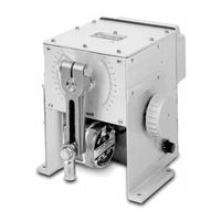
Honeywell HercuLine 10267A Installation, Operation And Maintenance Manual (86 pages)
Brand:
Honeywell
| Category:
Controller
| Size: 0.68 MB
Table of Contents
Table of Contents
5
1 Introduction
11
Product Description
11
Applications
11
Features
11
Non-Contact Position Sensing (NCS) with True Shaft Position Indication
11
Slidewire Emulation
12
Film Potentiometer
12
Motor Positioner Board
12
Auto/Manual Switch
13
Self-Locking/Releasing Gear Train
13
Motor
13
Manual Operation
13
All Position Mounting
13
Field Reversible
13
Customer Connections
13
Warranty
13
Honeywell Linkage Kits
14
Figure 1-1 10260A Actuator
14
Figure 1-2 10260A Internal View
15
2 Specifications and Model Selection Guide
17
Introduction
17
Specifications
17
Model Selection Guide
21
3 Installation
23
Introduction
23
Before Starting
23
Unpacking
23
Site Selection
23
Outline Dimension Drawings
23
Figure 3-1 Outline and Dimensions of 10261A, -62A, -64A, -66A, -67A, -68A, and -69A Actuators
24
Figure 3-2 Outline and Dimensions of 10263A and 10265A Actuators
25
Mechanical Installation
26
General
26
Linkage Set-Up
26
Figure 3-3 Constant Torque Linkage
26
Figure 3-4 Constant Torque Profile
27
Figure 3-5 Variable Torque Linkage
27
Figure 3-6 Variable Torque Profile
28
Figure 3-7 Turnbuckle Linkage Kit
28
Figure 3-8 Pipe Linkage Kit
29
Figure 3-9 Standard 5" Crank Arm
29
Projecting Scale Option
30
Figure 3-10 Projecting Scale Option
30
Electrical Installation
31
General Wiring Recommendations
31
Table 3-1 Recommended Minimum Wire Size
31
Customer Connections
32
Figure 3-11 Customer Terminal Connections (Non-Contact Sensor)
32
Figure 3-12 Customer Terminal Connections (Film Potentiometer)
33
Power Connections
34
CE Wiring
34
0/4-20 Ma, 0/1-5 VDC Input Signal Connections
34
0/4-20 Ma, 0/1-5 VDC Feedback Signal Connections
34
Slidewire Emulator Connections
35
Figure 3-13 Slidewire Connections
35
4 Calibration Procedures
37
Overview
37
Setting End-Of-Travel Limit Switches (Actuators Mfd. Pre-1/1/03)
37
Setting End-Of-Travel Limit Switches (Actuators Mfd. after 1/1/03)
38
Setting Auxiliary Switches (Actuators Mfd. Pre-1/1/03)
40
Figure 4-1 Location of Auxiliary Switches
41
Figure 4-2 End of Travel Limit Switch Settings
42
Figure 4-3 Auxiliary Switch Settings
42
Setting Auxiliary Switches (Actuators Mfd. after 1/1/03)
43
Non-Contact Sensor
44
Figure 4-4 Location of NCS Assembly
44
Motor Positioner Board
45
Overview
45
Available Adjustments
45
Table 4-1 Available Adjustments
45
ZERO and SPAN Adjustments
46
Fail-Safe Settings; Loss of Signal (L.O.S.)
46
Filter Settings
47
Deadband and Sensitivity Settings
47
Figure 4-5 Motor Positioner Board
47
Output Board Calibration
48
0/4-20 Ma PWA Output Board
48
Figure 4-6 0/4-20 Ma PWA Output Board
49
Slidewire Emulation
50
Figure 4-7 Slidewire Emulation Board
51
Reversal of Direction (Non Contact Sensor)
52
Reversal of Direction (Film Potentiometer)
52
Figure 4-8 Switch Jumper for Reversal
53
5 Start-Up/Operation
55
Introduction
55
Operations Checklist
55
6 Other Control Functions
57
Split Range
57
Master/Slave Arrangement
57
Basic Flow Control
58
Figure 6-1 Flow Diagram
58
Figure 6-2 Interconnection Diagram
58
Proportional Flow Using Multiple Actuators
59
Figure 6-3 Proportional Flow Using Multiple Actuators
59
Figure 6-4 Multiple Actuator Interconnection Diagram
60
Split Valve Configuration
61
Figure 6-5 Interconnection Diagram
61
7 Maintenance
63
Introduction
63
Basic Maintenance
63
Main Gear Lubrication
63
Spur Gear Lubrication
63
Non-Contact Sensor
63
Motor Positioner
63
Replacing the Fuses
63
8 Replacement/Recommended Spare Parts
65
Introduction
65
Motor Kits
65
Idler Gear Kits
67
Non-Contact Sensor, Film Potentiometer, Output Board Limit/Aux Switch and CAM Kits
67
Linkage Parts/Kits
71
Accessories
71
Non-Contact Position Sensor Field Upgrade Kits
72
Honeywell Actuator Linkage Analysis Software (HAL)
75
Replacement Fuses (Not for Sale)
75
Film Potentiometer Upgrade Kits
75
9 Troubleshooting
79
Introduction
79
Troubleshooting Procedures
79
Table 9-1 Observable Symptoms of Failure
79
Actuator Current Output Does Not Function
80
Table 9-2 Troubleshooting Current Output
80
Actuator Slidewire Output Does Not Function
81
Table 9-3 Troubleshooting Slidewire Output
81
Actuator CW/CCW Operation Is Not Correct
82
Table 9-4 Troubleshooting CW/CCW Operation
82
Actuator Does Not Control to the Proper Position
83
Table 9-5 Troubleshooting Control Action on Actuator
83
Auto/Manual Switch Does Not Operate Correctly
84
Table 9-6 Troubleshooting the Auto /Manual Switch
84
Actuator CW/CCW Switch Does Not Operate Correctly
85
Table 9-7 Troubleshooting the CW/CCW Switch
85
Actuator Up/Down Action Does Not Operate Correctly
86
Table 9-8 Troubleshooting the Up/Down Actuator Action
86
Related Products
Honeywell HercuLine 10267A-1-0-03-5-00010-000-00
Honeywell HercuLine 10261A
Honeywell HercuLine 10264A
Honeywell HercuLine 10263A
Honeywell HercuLine 10265A
Honeywell HercuLine 10262A-1-0-00-0-00003-100-00
Honeywell HercuLine 10264A-4-1-00-5-01100-012-00
Honeywell HercuLine 10266A-1-0-01-2-00010-000-00
Honeywell HercuLine 10266A-1-1-05-9-00002-100-00
Honeywell HercuLine 10268A-1-0-01-0-00202-000-00
Honeywell Categories
Thermostat
Controller
Control Unit
Security Camera
Accessories
More Honeywell Manuals