beautypg.com
Manuals
Brands
GE Manuals
Laboratory Equipment
LOGIQ S7 Pro
GE LOGIQ S7 Pro Manuals
Manuals and User Guides for GE LOGIQ S7 Pro. We have
1
GE LOGIQ S7 Pro manual available for free PDF download: Service Manual
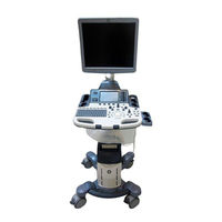
GE LOGIQ S7 Pro Service Manual (435 pages)
Expert Ultrasound System
Brand:
GE
| Category:
Laboratory Equipment
| Size: 11.41 MB
Table of Contents
Table of Contents
15
CHAPTER 1 Introduction
39
Overview
39
Purpose of Service Manual
39
Typical Users of the Basic Service Manual
40
Models Covered by this Manual
40
Purpose of Operator Manual(S)
41
Important Conventions
41
Conventions Used in this Manual
41
Standard Hazard Icons
42
Product Icons
43
Safety Considerations
45
Introduction
45
Human Safety
45
Mechanical Safety
45
Electrical Safety
46
Probes
46
Safe Practices
46
Auxiliary Devices Safety
46
Battery Safety (R2.X.X or Later)
48
Labels Locations
49
Dangerous Procedure Warnings
50
Lockout/Tagout Requirements (for USA Only)
50
Returning/Shipping System, Probes and Repair Parts
50
Electromagnetic Compatibility (EMC)
51
What Is EMC
51
Compliance
51
Electrostatic Discharge (ESD) Prevention
51
Customer Assistance
52
Contact Information
52
System Manufacturer
52
CHAPTER 2 Site Preparation
53
Overview
53
Purpose of Chapter 2
53
General Console Requirements
54
Environmental Requirements
54
Cooling
54
Lighting
54
Electrical Requirements
54
Inrush Current
55
LOGIQ™ S7 Expert/Pro Power Requirements
55
Main Power Plug
55
Site Circuit Breaker
55
Site Power Outlets
55
EMI Limitations
56
Probe Environmental Requirements
57
Time and Manpower Requirements
57
System Specifications
58
Acoustic Noise Output
58
Electrical Specifications
58
Physical Dimensions of LOGIQ™ S7 Expert/Pro
58
Facility Needs
59
Purchaser Responsibilities
59
Mandatory Site Requirements
60
Site Recommendations
60
Recommended Ultrasound Room Layout
61
Networking Setup Requirements
62
DICOM Option Pre-Installation Requirements
62
Purpose of the DICOM Network Function
62
Stand-Alone Unit (Without Network Connection)
62
Unit Connected to Hospital's Network
62
CHAPTER 3 Setup Instructions
63
Overview
63
The Purpose of Chapter 3
63
Set up Reminders
63
Average Installation Time
63
Installation Warnings
64
Moving/Lifting the System
64
OPIO Position
64
System Acclimation Time
64
Brake Pedal Operation
65
Safety Reminders
65
Receiving and Unpacking the Equipment
66
Packing Materials - Recycling Information
69
Preparing for Set up
70
Verify Customer Order
70
EMI Protection
71
Connection of Auxiliary Devices
72
Connecting the LCD Monitor
73
Connecting the Black & White Printer
74
Connection Scheme: B&W Printer
75
Connecting the Color Printer
76
Connection Scheme: Color Printer
77
Connecting the Secondary "Patient" LCD Monitor
78
Connecting the Footswitch
80
Connecting the USB Flash Memory Stick
81
Connecting the External USB Hard Disk (Handydrive)
81
General Remarks and Hints When Using External USB-Devices
82
External USB-Devices - Connection
82
External USB-Devices - Disconnection
82
Completing the Set up
83
Connecting the Unit to a Power Source
83
Power on / Boot up
83
Scanner Power on
83
Back End Processor Boot up
84
During a Normal Boot, You May Observe
85
Power off / Shutdown
87
Scanner Shutdown
88
Transducer Connection
90
Connecting the Probe
90
Activating the Probe
91
Cable Handling
91
Connecting the CW Pencil Probe
91
Deactivating the Probe
91
Disconnecting the Probe
91
Printer Installation
92
Installing Digital Color Printer Sony UP-D25MD
92
Installing the Bluetooth Deskjet Printer
93
Connecting the Bluetooth Dongle into the System
93
Verifying Bluetooth Device Driver
94
Bluetooth Pairing
95
HP Officejet 100
95
Prepare the Printer and Connect the Bluetooth Printer Adapter
95
Adding Printer to the System
96
Adjustment of Printer Settings
96
UP-D897 - Printer Settings
97
UP-D25MD - Printer Settings
98
Setting Printer to Print Reports
100
Setting up the Printer to Print Reports
100
System Configuration
101
System/General Preset Menu
101
External I/O Connectors
104
Available Probes
105
Supported Probes
105
Probe Description
105
Probe Naming Conventions
105
Software/Option Configuration
108
Connectivity Setup
109
Connectivity Introduction
109
The Dataflow Concept
109
Dataflow Examples
110
Connection between LOGIQ™ and DICOM Server
111
LOGIQ™ + PC Within a "Sneaker Net
111
Stand-Alone LOGIQ™ S7 Expert/Pro
111
Wired Ethernet from LOGIQ™ S7 Expert/Pro to a Workstation
112
Crossover Cable
112
Connection Via a Peer-To-Peer Network
112
Connection Via Hospital Network
112
Connection Using Wireless Option (R2.X.X or Later)
112
Configuring Connectivity
113
Overview
113
Structured Reporting
113
Supported Parameters
113
Connectivity Functions
114
Tcpip
115
Device
117
Service
118
Adding a Service to a Destination Device
118
Removing a Service
118
Changing Parameters for a Service
119
Connectivity Setup Worksheet
120
Paperwork
122
Product Locator Installation
122
User Manual(S)
122
CHAPTER 4 Functional Checks
123
Overview
123
Purpose of Chapter 4
123
Required Equipment
123
General Procedure
124
System Exterior Visual Check
124
Physical Abnormalities
124
Appearance Inspection
126
Mechanical Parts Functional Check
127
Main LCD
128
Lcd Arm
129
OPIO Swivel Lock
130
Swivel/Brake Lock Caster
131
Swivel/Brake Lock Caster
132
Power On/Off
133
Scanner Power on
133
Sleep Mode Check (R1.X.X)
135
Sleep Mode Check (R2.X.X or Later)
136
Complete Power down
137
Power off / Shutdown Check
138
System Information
139
Software Version
139
Service Platform Confirmation
140
USB Port Test
141
System Integration Checks
142
OPIO Test
142
DVD Drive Test
143
LAN Port Test
143
Peripheral Checks
144
Black and White Printer Test
144
CD/DVD Read/Writetest
144
Color Printer Test
144
DVR Test (if Equipped)
144
ECG Test
144
Gel Warmer Test
145
Single CWD
145
Mode Transition Checks
145
B-Mode
145
General Information
145
Color Flow-Mode
146
Pulse Doppler Mode
146
B/CF/PW Mode
147
M-Mode
148
OPIO Interface Check
150
Board Diagnostics
154
CHAPTER 5 Components and Functions (Theory)
157
Overview
157
Purpose of Chapter 5
157
General Information
158
System Exterior
158
Operator Panel
159
System Options
162
System Ports
162
Front USB
164
Rear USB
164
Hdmi
165
Rj45
166
Minijack
166
AC Inlet
166
Power on Sequence
167
Software Options
174
Options
174
Hardware Options
176
Options
176
Regional and Peripheral Options
178
Regional Options
178
Peripheral Options
178
Mechanical Descriptions
180
Physical Dimensions
180
LCD Monitor
180
OPIO Positioning
180
Air Flow Distribution
181
Exiting to Windows Desktop
182
Service Platform
184
Introduction
184
Access / Security
184
Local Access
184
How the Customer Enables/Disables Disruptive Mode and VCO
185
Common Service Desktop (CSD)
186
CSD Top Page
187
General Layout
187
Decoding System Temperature and Voltage
188
Error Logs
190
Diagnostics
190
Image Quality
191
Configuration
192
Utilities
193
Disk Defragmenter
193
Replacement
195
CHAPTER 6 Service Adjustments
197
Overview
197
Purpose of Chapter 6
197
Regulatory
197
LCD Monitor Adjustment
198
Brightness/Contrast
199
Brightness
199
Contrast
200
Gamma
200
Mode
200
Function
201
Scale
201
Information
201
Memory Recall
202
Sbc
202
Osd
203
Language
203
H-Position
203
V-Postion
203
Half Tone
203
Exit
204
OSD Control on the Utility Mode (R2.X.X or Later)
204
CHAPTER 7 Diagnostics/Troubleshooting
205
Overview
205
Purpose of Chapter 7
205
Collect Vital System Information
206
Collecting System Information
206
Request for Service (RFS)
207
Check Points Voltages
209
Visual Check
209
Common Power Supply (CPS/CPS2)
209
LED for Power Status
210
Voltage Measurement Points
211
Screen Captures and Logs
212
Capturing a Screen
212
System Warning/Errors and Logs
213
Temperature Warning
213
Cause
213
What to Do
213
Temperature Exceeded Threshold
213
Log Message of the High Temperature
213
System Voltage Failure
214
Cause
214
What to Do
214
Log Message of the Voltage Error
214
Hardware Configuration Error
215
Cause
215
What to Do
215
Log Message of the Invalid Hardware Error
215
System Error
216
Cause
216
What to Do
216
Log Message of System Error
217
Remote Access to Service Platform
219
General
219
How the Customer Enables/Disables Disruptive Mode and VCO
219
GE Icon and Remote Connection
219
Customer Granting Full Remote Access Permission to GE Service Technician
220
If GE Service Technician Requests Remote Access Permission
220
Common Service Desktop (CSD)
221
CSD: Configuration
221
Minimum Configuration to Boot/Scan
222
Troubleshooting Trees, Instructions and Tech Tips
223
System Does Not Boot up
224
Noise Disturbs the Image
225
Trackball - Impaired Sensitivity
226
Printer Malfunction
227
Monitor Troubleshooting
228
Overview
229
Returning/Shipping System, Probes and Repair Parts
231
CHAPTER 8 Replacement Procedures
232
Warnings and Important Information
232
Returning/Shipping Probes and Repair Parts
233
System Software - Installation/Upgrade Procedure
234
Preparation for Software Loading
235
System Software - Installation Procedure
247
System Software - Installation Procedure (R2.X.X or Later)
249
Application Software Installation Preparation
253
Application Software Installation
254
Software Installation from Common Service Desktop
257
Software and Functional Checks after Installation/Upgrade Procedure
261
Restore Procedures
262
Ezbackup and Ezmove
263
Option Keys
264
Replacement Front Cover
265
Installation Procedure
266
Replacement Top Cover
267
Installation Procedure
268
Replacement Side Cover
269
Removal Procedure - Side Cover (R)
271
Installation Procedure
272
Replacement Rear Cover
273
Replacement Side Tray & Footrest Cover
274
Removal Procedure - Foot Rest Cover
275
Replacement of Monitor and LCD Arm Plastic Covers
276
Monitor Installation Procedure
278
LCD Arm Plastic Covers Remove Procedure
279
LCD Arm Plastic Covers Installation Procedure
280
Replacement of OPIO and Related Parts
281
Removal Procedure - Trackball Ring
282
Removal Procedure - OP Panel Assy
283
Removal Procedure - an Keyboard
285
Removal Procedure - Trackball
286
Removal Procedure - LCD Touch Panel Assy
287
Removal Procedure - OP Panel Main PWA Assy
288
Removal Procedure - Joystick and Encoder on PWA
289
Installation Procedure
290
Replacement of the Caps for Hardkeys
291
Replacement of Key Caps (by Special Native Language Keys)
293
Replacement Procedure
294
Replacement Checking Procedure
296
Replacement Around ACQ Box
298
Removal Procedure - PIL, GBF128/64, GFS, CPS
300
Removal Procedure - Separating PIL and GBF128/64
302
Removal Procedure - Separating CWD Board from PIL
303
Separating DC4D Unit from CPS (for R1.X.X Only)
305
Installation Procedure
307
Removal Procedure - ACQ Box
308
Removal Procedure - Separating CBP (Backplane)
309
Replacement of CPS2 (R2.X.X or Later)
310
Installation Procedure
312
Replacement of CSI and Fan
313
Installation Procedure
315
Replacement of Rear Handle
316
Replacement of Caster
317
Installation Procedure
318
Replacement of the SOM,HDD and DVR
319
Removal Procedure (R2.X.X or Later)
322
Note on SOM Replacement
324
Note on EEPROM Replacement
325
Accessing EEPROM
326
Initializing EEPROM
327
Modifying Contents of EEPROM (Comexpress VPD)
329
Replacement of Battery (R2.X.X or Later)
330
Installation Procedure
331
Replacement of 4D
332
Replacement of Wireless Lan
333
Installation Procedure
334
Replacement of the Harness Cable, Cable Duct, and OPIO Cable Assy
335
Removal Procedure (Monitor Cable and OPIO Cable)
337
Installation Procedure
340
Replacement of Peripheral Cable Assy
341
Installation Procedure
342
B/W and Color Printer Cables
343
Installation Procedure
344
Replacement of the Probe Holder(Kit), Cable Hook, and Extended Probe Holder
345
Removal Procedure - Cable Hook
346
Removal Procedure - Extended Probe Holder
347
Replacement of AC Cable Holder
348
Replacement of the Peripherals
349
Installation Procedure
350
B/W on Side Cabinet
351
Installation Procedure
352
Installation Procedure
353
Color Printer on High Console
354
Installation Procedure
355
Replacement of the Speaker
356
Installation
357
Replacement of the Monitor Arm
358
Installation Procedure
362
Replacement of Drawer
363
Installation Procedure
364
Drawer on High Cabinet
365
Installation Procedure
366
Replacement ECG Module
367
Replacement of UVC
368
Installation Procedure
370
Replacement of DCWD ASSY
371
Overview
373
CHAPTER 9 Renewal Parts
374
List of Abbreviations
374
Parts List Groups
375
Plastics Covers (Front/Sides/Rear)
376
LCD Monitor
377
Opio
378
Nest Box Parts
383
Mechanical Parts
386
Mechanical Parts
387
Options
388
Optional Peripherals and Accessories
390
Probes
391
Power Cord
394
CHAPTER 10 Care & Maintenance
398
Why Do Maintenance
398
Tools Required
401
System Maintenance
402
Functional Checks
403
Peripheral/Option Checks
404
Air Filter Cleaning
405
Physical Inspection
406
Probe Maintenance
407
System Software Updates(Software Download)
408
Software Download and Installation
409
Using a Phantom
417
GEHC Leakage Current Limits
418
Outlet Test - Wiring Arrangement - USA & Canada
420
Grounding Continuity
421
Enclosure Leakage Current Test
422
Data Sheet for Enclosure Leakage Current
423
Generic Procedure
424
Type BF Patient Leakage Current Test - Probe
425
Type BF Patient Leakage Current - Mains to Probe
426
When There's too Much Leakage Current
427
New Unit
428
Related Products
GE LOGIQ S7 Expert
GE SE 250 Mighty Small II
GE SE 260 Mighty Small II
GE SEMIPHOR TRANSPHOR Series
GE SEMIPHOR TRANSPHOR UNIT
GE S768DAV
GE S7768DAV
GE Vivid S70
GE Vivid S70N
GE SSD3900J Series
GE Categories
Refrigerator
Ranges
Microwave Oven
Air Conditioner
Dishwasher
More GE Manuals