beautypg.com
Manuals
Brands
GE Manuals
Medical Equipment
LOGIQ P7
GE LOGIQ P7 Manuals
Manuals and User Guides for GE LOGIQ P7. We have
2
GE LOGIQ P7 manuals available for free PDF download: Service Manual, Technical Publication
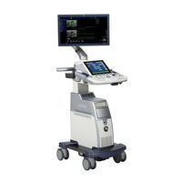
GE LOGIQ P7 Service Manual (602 pages)
Brand:
GE
| Category:
Medical Equipment
| Size: 54.89 MB
Table of Contents
Table of Contents
15
Overview
41
Purpose of Service Manual
41
Typical Users of the Basic Service Manual
42
Models Covered by this Manual
42
Purpose of Operator Manual(S)
43
Important Conventions
43
Conventions Used in this Manual
43
Standard Hazard Icons
44
Product Icons
45
Safety Considerations
48
Introduction
48
Human Safety
48
Mechanical Safety
48
Electrical Safety
49
Safe Practices
49
Probes
49
Auxiliary Devices Safety
50
Battery Safety
52
Labels Locations
53
Dangerous Procedure Warnings
55
Lockout/Tagout Requirements (for USA Only)
55
Returning/Shipping System, Probes and Repair Parts
55
Electromagnetic Compatibility (EMC)
56
What Is EMC
56
Compliance
56
Electrostatic Discharge (ESD) Prevention
56
Customer Assistance
57
Contact Information
57
System Manufacturer
57
Overview
59
Purpose of Chapter 2
59
General Console Requirements
60
Environmental Requirements
60
Cooling
60
Lighting
60
Electrical Requirements
60
LOGIQ P9/P7 Power Requirements
61
Inrush Current
61
Site Circuit Breaker
61
Site Power Outlets
61
Main Power Plug
61
EMI Limitations
62
Probe Environmental Requirements
63
Time and Manpower Requirements
63
System Specifications
64
Acoustic Noise Output
64
Electrical Specifications
64
Facility Needs
65
Purchaser Responsibilities
65
Mandatory Site Requirements
66
Site Recommendations
66
Recommended Ultrasound Room Layout
67
Networking Setup Requirements
68
Stand-Alone Unit (Without Network Connection)
68
Unit Connected to Hospital's Network
68
Purpose of the DICOM Network Function
68
DICOM Option Pre-Installation Requirements
68
Overview
69
The Purpose of Chapter 3
69
Set up Reminders
70
Average Installation Time
70
Installation Warnings
71
Moving/Lifting the System
71
System Acclimation Time
71
OPIO Position
71
Brake Pedal Operation
72
Safety Reminders
72
Receiving and Unpacking the Equipment
73
Packing Materials - Recycling Information
76
Preparing for Set up
77
Verify Customer Order
77
EMI Protection
78
Connection of Auxiliary Devices
79
Connecting the LCD Monitor
80
Connecting the Black & White Printer
81
Connection Scheme: B&W Printer
82
Connecting the Secondary "Patient" LCD Monitor
84
Connecting the Footswitch
85
Connecting the USB Flash Memory Stick
86
Connecting the External USB Hard Disk (Handydrive)
86
General Remarks and Hints When Using External USB-Devices
87
External USB-Devices - Connection
87
External USB-Devices - Disconnection
87
Completing the Set up
88
Connecting the Unit to a Power Source
88
Power on / Boot up
89
Scanner Power on
89
Back End Processor Boot up
90
During a Normal Boot, You May Observe
91
Power off / Shutdown
93
Scanner Shutdown
95
Transducer Connection
98
Connecting the Probe
98
Connecting the CW Pencil Probe
99
Cable Handling
99
Activating the Probe
99
Deactivating the Probe
99
Disconnecting the Probe
99
Printer Installation
100
Installing Digital Black & White Printer Sony UP-D898
100
Digital Color Printer Sony UP-D25MD
101
Installing the Bluetooth Deskjet Printer
102
Connecting the Bluetooth Dongle into the System
102
Verifying Bluetooth Device Driver
103
Prepare the Printer and Connect the Bluetooth Printer Adapter
104
HP Officejet 100
104
Bluetooth Pairing
104
Adding Printer to the System
105
Adjustment of Printer Settings
105
UP-D898 - Printer Settings
106
UP-D25MD - Printer Settings
107
Setting Printer to Print Reports
109
Setting up the Printer to Print Reports
109
System Configuration
110
System/General Preset Menu
110
External I/O Connectors
114
Available Probes
115
Supported Probes
115
Probe Naming Conventions
115
Probe Description
115
Software/Option Configuration
121
Connectivity Setup
122
Connectivity Introduction
122
The Dataflow Concept
122
Dataflow Examples
123
Stand-Alone LOGIQ P9/P7
124
LOGIQ? + PC Within a "Sneaker Net
124
Connection between LOGIQ? and DICOM Server
124
Wired Ethernet from LOGIQ P9/P7 to a Workstation
125
Crossover Cable
125
Connection Via a Peer-To-Peer Network
125
Connection Via Hospital Network
125
You will Need One Network Cable to Connect the LOGIQ P9/P7 to a Wall Outlet on the Hospital's Network
125
Connection Using Wireless Option
125
Configuring Connectivity
126
Overview
126
Structured Reporting
126
Supported Parameters
126
Tcpip
128
Device
130
Service
131
Adding a Service to a Destination Device
131
Removing a Service
131
Changing Parameters for a Service
132
Agent Configuration (R3 Only)
133
Agent Configuration
133
Verifying Back Office Connection - CSD
135
Verifying Back Office Connection - VOC
136
Connectivity Setup Worksheet
138
Paperwork
140
Product Locator Installation
140
User Manual(S)
140
Overview
141
Purpose of Chapter 4
141
Required Equipment
141
General Procedure
143
System Exterior Visual Check
144
Physical Abnormalities
144
Appearance Inspection
145
Appearance Inspection (R3)
146
Mechanical Parts Functional Check
147
Main LCD
148
Lcd Arm
149
OPIO Swivel Lock
150
Swivel/Brake Lock Caster
151
Power On/Off
153
Scanner Power on
153
Sleep Mode Check
155
Complete Power down
156
Power off / Shutdown Check
157
System Information
158
Software Version
158
Service Platform Confirmation (R1, R2, R2.5 Only)
159
USB Port Test
160
System Integration Checks
161
OPIO Test
161
DVD Drive Test
162
LAN Port Test
162
Peripheral Checks
163
DVR Test (if Equipped)
163
Black and White Printer Test
163
Color Printer Test
163
CD/DVD Read/Writetest
163
ECG Test
163
Gel Warmer Test
164
Single CWD
164
Mode Transition Checks
164
General Information
164
B-Mode
166
Color Flow-Mode
167
Pulse Doppler Mode
168
B/CF/PW Mode
168
M-Mode
170
B-Flow Mode
170
CW Mode (Optional)
171
WLAN (Optional)
172
Mode (Optional)
172
Power Assistant (Optional)
172
OPIO Interface Check (R1, R2, R2.5 Only)
173
OPIO Interface Check (R3 Only)
176
Touch Panel Calibration (R3 Only)
179
Board Diagnostics
182
Overview
185
Purpose of Chapter 5
185
General Information
186
System Exterior
186
Operator Panel
187
System Options
189
System Ports
190
Front USB
191
Rear USB and LAN
191
Hdmi
193
S-Video / Composite
194
AC Inlet
195
Power on Sequence
196
Software Options
197
Options
197
Smart Devices Applications (LOGIQ Apps)
200
Hardware Options
201
Options
201
Regional and Peripheral Options
203
Regional Options
203
Peripheral Options
203
Mechanical Descriptions
204
Physical Dimensions
204
LCD Monitor
204
OPIO Positioning
204
Air Flow Distribution
205
Exiting to Windows Desktop
206
Service Platform
208
Introduction
208
Access / Security
208
Local Access
208
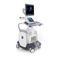
GE LOGIQ P7 Technical Publication (127 pages)
Ultrasound System
Brand:
GE
| Category:
Medical Equipment
| Size: 3.71 MB
Table of Contents
Table of Contents
21
Chapter 1 - Overview
25
Content in this Manual
26
Product Description
27
Overview of the Ultrasound System
27
Products Covered in this Manual
28
Chapter 2 - Safety Information
29
Overview
30
Contents in this Chapter
30
Important Conventions
31
Conventions Used in Book
31
Standard Hazard Icons
33
Product Icons
35
Label Icon Description
35
How to Lock the Operator Panel Prior to Transport
35
Safety Considerations
36
Introduction
36
Human Safety
36
Mechanical Safety
39
Electrical Safety
44
Label Locations
46
Product Labels
46
Dangerous Procedure Warnings
47
Warnings
47
Lockout/Tagout (LOTO)
48
LOTO Requirements
48
Returning Probes and Repair Parts
49
Requirements for Returning Parts
49
User Responsibility
49
Electromagnetic Compatibility (EMC)
50
What Is EMC
50
Compliance
50
Electrostatic Discharge (ESD) Prevention
51
Chapter 3 - Site Preparations
53
Overview
54
Contents in this Chapter
54
General Ultrasound System Requirements
55
Contents in this Section
55
Ultrasound System Environmental Requirements
55
Electrical Requirements
57
EMI Limitations
70
Probes Environmental Requirements
72
Time and Manpower Requirements
72
Facility Needs
73
Contents in this Section
73
Purchaser Responsibilities
73
Required Facility Needs
75
Desirable Features
77
Care and Maintenance
79
Contents in this Chapter
80
Chapter 4 - Care and Maintenance
81
Warnings
81
Why Do Maintenance
82
Keeping Records
82
Quality Assurance
82
Maintenance Task Schedule
83
How Often Should Maintenance Tasks be Performed
83
System Maintenance
84
Preliminary Checks
84
Functional Checks
85
Physical Inspection
87
Cleaning
89
Probe Maintenance
90
Using a Phantom
91
Phantoms
91
Electrical Safety Tests
92
Content in this Section
92
Uninterrupted Power Supply (UPS)
93
Safety Test Overview
94
Leakage Current Limits
97
Outlet Test - Wiring Arrangement - USA and Canada
101
Grounding Continuity
102
Chassis Leakage Current Test
103
Isolated Patient Lead (Source) Leakage-Lead to Ground
107
Isolated Patient Lead (Source) Leakage-Lead to Lead
109
Isolated Patient Lead (Sink) Leakage-Isolation Test
111
Probe (Source) Leakage Current Test
113
Isolated Probe (Sink) Leakage-Isolation Test
118
When There's too Much Leakage Current
122
AC/DC Fails
122
Chassis Fails
122
Probe Fails
123
Peripheral Fails
123
Still Fails
123
New Ultrasound System
123
ECG Fails
123
Ultrasound Equipment Quality Check (EQC and IQC)
124
Quality Checks
124
Related Products
GE LOGIQ P3 VET
GE PhastSystem
GE ProSpeed S
GE ProSpeed SX Lemage
GE ProSpeed Lemage Supreme
GE ProSpeed VX
GE ProSpeed ProSeed
GE VIVID 3 N PRO BT03
GE Voluson P6 BT16
GE DINAMAP PRO 100V2
GE Categories
Refrigerator
Ranges
Microwave Oven
Air Conditioner
Dishwasher
More GE Manuals