beautypg.com
Manuals
Brands
GE Manuals
Medical Equipment
Datex-Ohmeda S/5 Series
GE Datex-Ohmeda S/5 Series Manuals
Manuals and User Guides for GE Datex-Ohmeda S/5 Series. We have
1
GE Datex-Ohmeda S/5 Series manual available for free PDF download: Technical Reference Manual
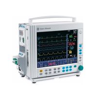
GE Datex-Ohmeda S/5 Series Technical Reference Manual (335 pages)
Compact Anesthesia Monitor, Compact Critical Care Monitor
Brand:
GE
| Category:
Medical Equipment
| Size: 4.83 MB
Table of Contents
Table of Contents
7
Table of Figures
10
About this Manual
11
1 Introduction
13
Figure 1 S/5 Compact Anesthesia Monitor System
13
Symbols
15
Symbols on Equipment
15
Symbols on Transport Packaging
15
Equipment Safety Symbols
16
Other Symbols
17
Safety
20
Safety Precautions
20
ESD Precautionary Procedures
23
Disposal
24
2 System Description
25
Introduction
25
Bus Structure
25
Figure 2 General Bus Structure of S/5 System
25
Distributed Processing
26
Module Communication
26
Figure 3 Principle of UPI Section Operation
26
Software Loading
27
Parameter Modules
27
Figure 4 General Structure of Parameter Modules with Patient Isolation
27
3 System Installation
29
Unpacking Instructions
29
Choosing Location
29
S/5 Frame for Compact Monitor
29
Compact Monitor Connections
30
Figure 5 External Connections of Compact Monitor Frame F-CM(C)1 Rev.05
30
Connecting to Mains
31
Figure 6 External Connections of Compact Monitor Frame F-CM(C)1 Rev.00
31
Connecting to Network
32
Connecting to Wireless Network
32
E-PSM(P) Mounting Accessories
33
Inserting the Parameter Modules
33
Figure 7 E-PSM(P) Mounting Accessories
34
Downloading Monitor Software
35
Installing the Datex-Ohmeda Network and Memcard Upgrade, U-CMMEM
36
Performing Factory Reset
36
Installing the Datex-Ohmeda Network Upgrade, U-CMNET
37
Installing the S/5 Wireless LAN Upgrade, U-CMW
37
Installing the S/5 Recorder Upgrade, U-CMREC1
38
S/5 Remote Controller, K-CREMCO
39
Anesthesia Record Keeping Keyboard, K-ARKB
39
ARK Barcode Reader, N-SCAN (Optional)
39
Connection to Compact Monitor
39
Figure 8 Installation of the U-CMREC1
39
S/5 Compact Airway Modules, E-XXXX / M-XXXXX
40
Figure 9 ARK Barcode Reader, N-SCAN Connected to Compact Monitor
40
Figure 10 Compact Airway Module, E-XXXX
40
Figure 11 Scavenging through Ventilator Reservoir
41
Sample Gas Exhaust
41
Figure 12 Connecting the Gas Module to the Scavenging Connector of S/5 Avance
42
Figure 13 Sample Gas Returned to Patient Circuit in ADU
43
Troubleshooting
43
4 Interfacing
45
Interfacing External Monitors Via Interface Module, E-INT / M-INT
45
Connection to External Datex-Ohmeda Monitors
46
Connection to Baxter Vigilance
47
Connection to Critikon Dinamap 1846SX, Abbott Oximetrix 3 and Baxter Explorer
47
Connection to Nellcor N-100 and N-1000
47
Connection to Nellcor N-200
47
Interfacing External Bedside Devices Via Device Interfacing Solutions, N-Disxxx
48
Connections
49
Device Interfacing Solution Components
49
Figure 14 Connection Cables and LED Indicators
50
Mounting
50
Figure 15 an Example of Interfacing External Devices with Device Interfacing Solution
51
Selecting the External Device
51
Functional Check
52
Selecting the Parameter Data Source
52
Interfacing Datex-Ohmeda Anesthesia Delivery Unit
53
Interconnection
53
Setting Interfacing Parameters on the S/5 Anesthesia Delivery Unit
53
Setting Interfacing Parameters on the S/5 Compact Anesthesia Monitor
53
Interfacing Dräger Cicero, Cato, Julian and Narkomed 2C (by NAD)
54
Interconnection
54
S/5 Compact Critical Care Monitor
55
Setting Communication Parameters
55
Setting Interfacing Parameters on the S/5 Compact Anesthesia Monitor or
55
Interfacing Printer
57
Connection to Parallel Printers
57
Connection to Serial Printers
57
Installing the Serial-To-Parallel Converter
57
Setting S/5 Compact Monitor Interface for Printers
57
Figure 16 Connecting S/5 Compact Monitor to Printer, Converter Model PI130-R2
58
Connection to Printer
59
Interfacing Computer
59
Output Signals
59
Figure 17 Connecting S/5 Compact Monitor to Printer, Converter Model PI 1115A
59
Analog Outputs
60
Digital Outputs
60
S/5 Pressure Temp Module, E-PT or M-PT, Output Signals
61
5 Functional Check
63
Recommended Tools
63
Hemodynamic Patient Simulators
65
Visual Inspection
66
Functional Inspection
67
General
67
Display
68
Display Unit
68
Frame Unit
68
Keyboard(S)
68
Figure 18 S/5 Compact Monitor General Troubleshooting Flowchart
75
Figure 19 Software Troubleshooting
76
Table of Contents
91
1 Planned Maintenance Instructions
93
Introduction
93
Recommended Tools
94
Hemodynamic Patient Simulators
96
Recommended Parts
97
Planned Maintenance Parts
97
PM Parts for Compact Airway Modules, E-CXX/ M-CXX Without CO2 Absorber - Anesthesia
97
Anesthesia
98
PM Parts for Compact Airway Modules, E-CXX/ M-CXX with CO2 Absorber
98
PM Parts for Compact Airway Modules, E-CXX/ M-CXX Without CO2 Absorber - Critical Care
98
PM Parts for Airway Module, E-Minic/ M-Minic
99
2 Planned Maintenance Check List
101
Visual Inspection/Preparation
101
Compact Airway Module, E-CXX/ M-CXX
101
General
101
Single-Width Airway Module, E-Minic/ M-Minic
102
Tonometry Module, E-TONO/ M-TONO
102
Modules with NIBP Measurement
103
Recorder Unit
103
Functional Inspection
103
General
103
Compact Airway Module, E-CXXXXX/ M-CXXXXX
105
Display
105
Display Unit
105
Frame Unit
105
Keyboard(S)
105
Single-Width Airway Module, E-Minic/ M-Minic
107
Tonometry Module, E-TONO/ M-TONO
107
Multiparameter Hemodynamic Modules
108
Table of Contents
125
Introduction
129
1 Frame
131
Memory
131
Network
132
Network Status
132
Ethernet
134
Network Config
134
Table 1 Ethernet Service Data
135
Wlan
136
Memcards
138
Status
138
Communication
139
Power Supply
140
Battery
141
PCMCIA Board
141
2 Display
142
3 Keyboard
143
Keyboard Log
144
Keyboard Type
144
4 Parameters
145
Gas Unit
145
General
146
Gases
147
Spirometry
148
ECG Module
150
ECG Setup
151
ESTP Module
152
Calibrations
154
P/Pt
155
P/PT Calibrations
156
PP Calibrations
158
Cop
159
COP Calibrations
160
NIBP Module
161
NIBP Demo
162
NIBP Calibration
163
NIBP Safety Valve
164
NIBP Pulse Valve
165
NIBP Buttons/Leds
166
NIBP Pneumatics
167
NIBP Watchdog
168
Nmt
169
NMT Setup
170
Oxygen Saturation Modules, E-NSAT, E-NSATX, M-NSAT, M-OSAT
171
More
172
Interface Module, E-INT, M-INT
173
Gases
174
Sp02
174
Nibp
175
Spirometry
175
Sv02/C.o
176
Tonometry
177
Table 2 Module General Status
177
Table 3 Module Hardware Status
178
Table 4 Module Keyboard Status
178
Table 5 Module General Error Status
178
Table 6 Module Pneumatics Error Status
179
Table 7 Module Hardware Error Status
180
Tonometry
181
Press Sensor
182
System Test
183
Table 8 Description of System Test
184
Pneumatics
186
Eeg & Ep
188
EEG & EP Setup
189
Bis
191
Table 9 Module General Status
192
Table 10 bis Engine Status
192
Table 11 bis Engine and DSC Error Messages
193
Sensor
194
Table 12 DSC Status
195
Table 13 Sensor Status
195
Table 14 be Power up Status
195
BIS Setup
196
Entropy
197
Sensor
198
DIS Interfacing
199
Interfacing
199
DIS Interfacing
200
Status Page
200
DIS Module Specific Page
201
5 Set/Test
202
Country Settings
203
6 Service Log
204
Maintenance
205
Planned Maintenance
205
Repair
206
Upgrade
206
Error History
207
Event History
207
Alarm History
208
7 Record Data
209
8 Remote Access
210
Appendix A: How to Read HEX Numbers
211
Table of Contents
215
Introduction
219
1 Specifications
220
S/5 Compact Monitor, F-CM1, F-CMREC1, F-CMC1, F-CMCREC1; Display Unit
220
LCD Display
220
Memcard Option
220
Network Option
220
Wireless LAN Option
220
Recorder Option
221
Digital Outputs of Display Unit
221
2 Display Unit Functional Description
222
CPU Section
222
Standby and Display Unit Power down
223
Watchdogs
223
Sram Mt48T37V
224
UPI Section
225
CPU Bus Interface
225
Functional Blocks
225
Processor
225
Serial Bus Interface
225
Software License, L-CANE06, L-CANE06A, L-CICU06, L-CICU06A
226
Display Controller Section
226
Display Controller Resolution
226
Display Memory
226
MEM Section
227
Memory Card Interface
227
Power Supply
227
NET Section
228
Ethernet Interface
229
Wireless LAN
230
Front Unit
231
Backlights
232
Connector Board
232
Keyboard
232
Display Unit DC/DC Power Supply
232
Connectors and Signals
233
External Connectors
233
Serial Data Interface
236
Digital and Analog Outputs
237
Printer Connection
237
3 Service Procedures
238
General Service Information
238
Service Check
238
Recommended Tools
238
Before Beginning
239
Recommended Parts
239
Visual Inspection
239
Functional Inspection
241
Disassembly and Reassembly
251
To Disassemble the Display Unit F-CM(C)1 Rev.04 and 05
251
To Disassemble the Display Unit of F-CM(C)(REC)1 Rev.00
253
To Remove the Central Processing Board (CPB) from the Display Unit Back Unit
254
To Remove the Display Unit DC/DC Power Board
254
Disassembling the Connector Board and Inverter Board
255
To Disassemble the LCD Display Element, F-CM(C)(REC)1 Rev. 00
255
To Remove the Loudspeaker and Fan
255
To Remove the Net Unit
255
To Remove the Synchronization Unit
255
Changing the LCD Backlight, F-CM(C)1 Rev.03, Rev.04 and Rev.05
257
Changing the LCD Backlights, F-CM(C)(REC)1 Rev.00
257
Changing the LCD Backlights, F-CM(C)(REC)1 Rev.01, Rev.02
257
Downloading the Software on Empty Central Processing Board
258
Handling and Storage of LCD Display Component
258
Performing Factory Reset
259
Adjustments and Calibrations
259
4 Troubleshooting
260
General (Display Unit)
260
Software License (Service Software)
261
Error Messages
262
Memory Option
262
Troubleshooting for the NET Section
263
5 Earlier Revisions
265
Appendix A: Service Check Form, S/5 Compact Anesthesia Monitor, S/5 Compact Critical Care Monitor
267
Table of Contents
273
Introduction
275
1 Specifications
276
2 Functional Description
277
PMB Connector Board
278
Connector Board PMB-REC
278
PMB (Power Management Board)
279
Module Motherboard
280
AC/DC Power Supply Unit
281
Batteries
281
Frame Unit Fan
281
In-Built Recorder Unit
281
Connectors and Signals
282
External Connectors
283
Serial Data Interface
284
3 Service Procedures
285
General Service Information
285
Service Check
285
Recommended Parts
285
Recommended Tools
285
Before Beginning
286
Visual Inspection
286
Functional Inspection
288
Recorder Unit
290
General
291
Disassembly and Reassembly
293
To Remove the AC/DC Unit
293
To Remove the Batteries
293
Adjustment and Calibrations
294
To Detach/Remove the Module Mother Board
294
To Disassemble the Side Frame Unit
294
To Remove the Recorder Unit
294
Internal Battery
295
Battery Time
295
Refreshing the Batteries
295
Replacing the Batteries
295
4 Troubleshooting
297
General
297
Table of Contents
307
1 Compact Monitor Display Unit
309
F-CM(C)REC1 Rev. 00, 01, F-CM(C)1 Rev.00
309
Display Unit, Bottom Unit, F-CM(C)REC1 Rev. 00, 01, F-CM(C)1 Rev.00
311
Display Unit, Bottom Unit, F-CM(C)1 Rev.04 and 05
313
Front Unit, F-CM(C)(REC)1 Rev. 00
315
Front Unit, F-CM(C)REC1 Rev. 01, F-CM(C)1 Rev.01, Rev.02
317
Front Unit, F-CM(C)1 Rev.03
319
Central Processing Board
320
2 Compact Monitor Frame
321
F-CM(REC)1, F-CMC(REC)1 Rev. 00
321
S/5 Compact Monitor Frame, F-CM(C)1 Rev. 01, Rev. 02, Rev. 03, F-CM(C)REC1 Rev.01
323
Side Frame Unit, F-CM1, F-CMC1 Rev.02, Rev.03
325
S/5 Compact Monitor Frame, F-CM(C)1 Rev. 04 and 05
326
3 Software Licenses
328
4 Upgrade Kits
330
Related Products
GE Datex-Ohmeda Aisys Carestation
GE Dash 3000
GE Dash 4000
GE Dash 5000
GE Dash 2500
GE DASH 3000 V5
GE DASH 4000 V5
GE Dash Responder
GE Discovery LS
GE Definium 5000
GE Categories
Refrigerator
Ranges
Microwave Oven
Air Conditioner
Dishwasher
More GE Manuals