beautypg.com
Manuals
Brands
GE Manuals
Medical Equipment
Corometrics 126
GE Corometrics 126 Manuals
Manuals and User Guides for GE Corometrics 126. We have
1
GE Corometrics 126 manual available for free PDF download: Service Manual
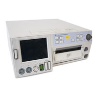
GE Corometrics 126 Service Manual (440 pages)
Corometrics 120 series
Brand:
GE
| Category:
Medical Equipment
| Size: 11.41 MB
Table of Contents
Table of Contents
7
Safety
21
General Information
22
General Use
22
Responsibility of the Manufacturer
22
Responsibility of the User
22
Definitions of Terminology
23
Monitor Contraindications, Warnings, and Precautions
24
Warnings
24
Cautions
27
Electromagnetic Interference
28
Equipment Symbols
29
Introduction
31
Indications for Use
32
Fetal Monitoring
32
Maternal Monitoring
32
Blood Pressure
32
Heart/Pulse Rate
32
Pulse Oximetry
32
Series Overview
33
The Model 126 Monitor
33
The Model 128 Monitor
35
The Model 129 Monitor
36
Upgrading Your Monitor
36
Adding Fetal Movement Detection
36
Illustrations
37
About the Manual
37
Design Changes
38
References to Persons, Places, and Institutions
38
Controls, Indicators, and Connectors
39
Front Panel Description
40
Front Panel Displays
43
Display Example
43
Primary Labor Parameters
45
FHR Display
45
UA Display
47
Additional Parameters
48
Maternal NBP
48
MHR/P Area
49
Fspo Area
50
Mspo 2 Area
51
Time and Waveform Message Area
51
Waveform Area
51
Battery-Backed RAM Status
52
Dedicated Softkey Area
52
Mode Title Softkeys
52
Softkeys
52
Waveform Softkeys
52
Rear Panel Description
55
Communication Option
58
J101 Connector
58
J102 Connector
58
J103 Connector
58
J104 Connector
58
Corolan Option
58
Theory of Operation
59
Chapter 4
60
Main Motherboard
60
Functional Overview
60
Switch/Status Input Data Flow Diagram
60
External/Internal Communication Data Flow
60
Audio Control Flow
60
Control Block
78
Corolan Module
78
Options Interface
80
Rear Panel Interface
80
Audio Section
80
Recorder Interface Section
81
RS-232C Communications Section
81
DSP Board
82
Functional Overview
82
DSP Section
82
Control Module
82
Watchdog Module
82
Front-End Control/Status Interface
83
Status/Control Module
83
IUP Interface
83
Analog Conversion Module
83
Front Panel Interface Section Theory
83
EL Panel Interface
83
Front Panel Switch Interface
85
Recorder LED Board Interface
92
NBP Board
93
NBP Board with DINAMAP or Marquette Electronics Technology
93
AC Amplifier and Filter
93
DC Pressure Amplifier and Filter
93
Pressure Transducer and Amplifier
93
Microcontroller and Host Interface
94
MUX and A/D
94
Pump/Valve Control
94
NBP Board Manufactured by cas Medical Systems, Inc
95
A/D Conversion
95
Processor Circuitry
95
Watchdog Circuitry
95
Instrumentation Amplifier
96
Valves
96
Communications Board
97
Central Systems Interface
97
Model 2116B Keyboard Interface
98
Model 340 Telemetry Interface
98
System Power Supply
102
Display Board
103
Dual Ultrasound Board
104
Overview
104
The Ultrasound Transducer
104
Ultrasound Oscillator
104
Digital Control Section
105
Channel a Pin Diode Circuitry
106
Channel B Pin Diode Circuitry
106
Transmission, Channel a or Channel B
107
Reception, Channel a or Channel B
107
Channel a Filtering
108
Audio Circuitry
108
Main Filters
108
Fetal Movement Filters
109
Ultrasound Envelope
109
UA/FECG Board
110
Isolated FECG Circuitry
110
Isolated UA Circuitry
111
MECG Board
119
Defibrillator Protection
119
Input Lead Switching
119
Single-Wire ECG Amplifier with Right Leg Drive
120
Pacemaker Detection
121
Leads off Detection
123
Test Generator
124
Linear Isolation Amplifier
124
Low-Pass and Notch Filters
125
Oximeter Carrier Board
128
Mspo 2 Board
129
Nellcor Module
129
Functional Overview
129
Input Source Selection Circuits
129
LED Driver Circuitry
129
Filters/Amplifiers
130
Input Amplifier and Synchronous Detector
130
Analog-To-Digital Conversion Circuitry
131
Communications
131
Processor Circuitry
131
Masimo Module
131
Principle of Operation
131
Isolated Power Supply Board
134
Controller
134
External Synchronization
135
Fly-Back Transformer, Output Rectification, and Filtering
135
Isolated Feedback
136
Short Circuit Protection
137
Input Filter/Isolation Barrier
137
Recorder Board
140
Setup Procedures
145
Chapter 5
146
Loading Strip Chart Recorder Paper
146
Mounting a Strain Gauge for IUP Monitoring
149
User Setup Screens
150
Using the Trim Knob Control
150
FECG Setup Screen
152
Volume
152
FHR Alarm Limits
152
FHR Audio Alarm
152
Alarm Volume
152
US/US2 Setup Screen
153
Fetal Movement Detection
153
Fetal Heart Rate Offset
153
Volume
154
FHR Audio Alarm
154
Alarm Volume
154
Maternal NBP Setup Screen
155
Display Timer
155
Mode
155
NBP Done Volume
156
Alarm Limits
156
Audio Alarm
156
Master Alarm Volume
156
Mspo2 Setup Screen
157
Response Time (Nellcor Module Only)
157
Sensitivity (Masimo Module Only)
157
Averaging Time (Masimo Module Only)
158
Print Interval
158
O 2 Trace
158
Alarm Limits
158
Audio Alarm
158
Alarm Volume
158
MHR/P Setup Screen
159
Source
159
MHR/P Trace
159
Volume
160
Alarm Limits
160
Audio Alarms
160
Alarm Volume
160
MECG Lead
160
MECG Pacer
161
Response Time
161
Master Alarm Setup Screen
162
Audio Alarms
162
Re-Alarm
162
Alarm Limits
162
Volume
162
Response Time
163
Print Interval
163
Fspo2 Setup Screen
163
O 2 Trace
164
Fspo 2 Display Area
164
Fspo 2 Status Icons
164
Pulse Search
164
Sensor Lifted
164
Sensor Unplugged
164
Single Versus Dual Display of Spo 2
164
General Setup Screen
166
Date
166
Song Player
166
Song Player Volume
166
Time
166
Paper Chime
167
Paper Speed
167
Recorder Light
167
Spo Scale
167
Fspo 2 Print Interval
168
Fspo 2 Trace
168
Mspo 2 Print Interval
168
Paper Chime Volume
168
Service Mode Screens
169
Service Lock Screen
169
Install Options Screen
170
Current (Last-Used) Settings
171
Default Settings
171
Factory Defaults
171
Hospital Defaults
171
Volume Exceptions
171
ECG Artifact Elimination
172
HR Offset
172
Language
172
Line Frequency
172
NBP One-Minute Interval
172
New Hospital
172
Scaling
172
10 Min
173
Default TOCO Reference
173
FM Remote Mark
173
Off
173
What Is It
173
Corolan Address Checking
174
Heartbeat Coincidence
174
Recorder Font Size
174
Smart BP
174
VS Print Interval
174
Alert Suspend
175
Fetal Alert/Alarms
175
Printing System Setup Information
175
Communications Setup Screen
177
Baud Rate
177
Mode
177
Hardware Switches
178
Functional Checkout Procedure
179
Before You Begin
180
Equipment Required
180
General
180
Self-Test Routine
181
Front Panel Pushbutton Test
183
Connecting the Simulator
184
MECG Test
185
FECG Test
189
Ultrasound Test
194
Fetal Movement Detection Test
197
Ultrasound Transducer Test
199
Uterine Activity Test
200
Tocotransducer Test
203
Strain Gauge Transducer Test
204
Pattern Memory Test
205
Dual Heart Rate Test (Non-Pattern)
206
FECG/US Modes
206
Dual Ultrasound Modes
209
Alarm Test
210
NBP Test
213
Mspo 2 Test
213
Preventative Maintenance Inspection Report
214
Configuration
214
Tools Required
214
Visual Inspection
214
Inspection Checklist
215
Calibration
219
Chapter 7
220
Before You Begin
220
General
220
Power Supply Voltages-Verification
221
Main Board Power Supply Voltages
221
Isolated Power Supply Board Voltages
222
Isolated FECG/UA Board Voltages
222
Recorder Photosensor Calibration
223
Adjusting the Paper-Low Photosensor
223
Adjusting the Paper-Out Photosensor
224
Adjusting the Paper-Loading Sensor
224
Display Check
225
Checking a 3" X 3.75" Display
226
Verifying the DSP Board Operation (3"X 3.75" Display)
226
Removing the Display Assembly
227
Replacing the Display Assembly
228
Disassembly
229
Equipment Required
229
Upgrading to a 3.5" X 4.5" Display
229
Reassembly
230
Testing
234
Checking a 3.5" X 4.5" Display
235
Verifying the DSP Board Operation
235
Removing the Display Assembly
236
Replacing the Display Assembly
237
Trimline Tocotransducer Calibration
238
Equipment Required
238
Procedure
238
Nautilus Tocotransducer Calibration
241
Equipment Required
242
Calibration Procedure
243
Calibration for Cat. No. (REF) 2264 GAX/HAX/JAX/KAX/LAX/MAX
243
Disassembly
243
Calibration for Cat. No. (REF) 2264 AAX/BAX/CAX/DAX/EAX/FAX
244
Reassembly
245
Testing the Tocotransducer
245
Maternal Spo2 Calibration
246
Calibration
246
Self-Tests
247
Chapter 8
248
Power-On Diagnostic Tests
248
Monitor Self-Test
249
Error Log Screen
251
Diagnostic Control Screen
257
Recorder Calibration Test
258
CPU Version
258
DSP Version
259
Run Time
259
Recorder Time
259
Main Board SW1 Switch Settings
259
Corolan Network Status
260
Corolan Address Check
263
J102 Analog Output Connector DAC Static Test
264
Verification
264
Analog Ground
264
HR1 and HR2
264
HR1 Mode
265
HR2 Mode
265
Markout*, Check Paper*, FMD1, and FMD2
265
UA Mode
265
Calibration
265
RS-232C Connector Loopback Test
267
Making a Loopback Test Connector
267
Testing the Port(S)
267
General Maintenance
269
Chapter 9
270
Cleaning
270
Cleaning the Monitor Exterior
270
Cleaning the Electroluminescent Panel
270
Cleaning the Tocotransducer, Ultrasound Transducer, and MECG Cables
271
Cleaning the UA Strain Gauge
272
Cleaning the Maternal NBP Cuffs and Hoses
272
Main Board Battery
273
Maternal Blood Pressure Tests
274
Accessing the Diagnostic Control Screen
274
Manometer Pressure Check
277
Pneumatic Pressure Check
279
Electrical Safety Tests
280
AC Line
280
Ground Impedance
280
Initial Conditions
280
Unit to Primary Leakage
281
Patient-To-Ground Leakage for ECG
282
Patient-To-Line Leakage for ECG
283
Patient-To-Ground Leakage for IUP
284
Patient-To-Line Leakage for IUP
285
Patient-To-Ground Leakage for Mspo
286
Patient-To-Line Leakage for Mspo
287
Patient-To-Ground Leakage for Fspo
288
Patient-To-Line Leakage for Fspo
289
Patient-To-Ground Leakage for US
290
Patient-To-Line Leakage for US
291
Patient-To-Ground Leakage for US2
292
Ground Continuity
293
Patient-To-Line Leakage for US2
293
Dielectric (Hi-Pot) Tests
294
Patient-To-AC-Line Using DC Voltage for One Minute
294
Patient-To-Chassis Using AC Voltage for One Minute
296
Mains-To-Chassis Using DC Voltage for One Minute
297
Strip Chart Recorder Servicing
299
Chapter 10
300
Removing the Strip Chart Recorder
300
Installing the Strip Chart Recorder
301
Periodic Thermal Printhead Cleaning
302
Field Serviceable Assemblies
303
Stepper Motor and Harness
303
Removing the Stepper Motor
303
Replacing the Stepper Motor
303
Printhead Adjustments
304
Horizontal Offset Adjustment
304
Vertical Offset Adjustment
304
Removing the Printhead
306
Replacing the Printhead
306
Thermal Printhead
306
Paper-Low/Paper-Out Photosensor
310
Adjusting the Paper-Low Photosensor
310
Removing the Paper-Low/Paper-Out Photosensor
310
Replacing the Paper-Low/Paper-Out Photosensor
310
Adjusting the Paper-Out Photosensor
311
Paper-Loading Sensor
312
Removing the Paper-Loading Photosensor
312
Replacing the Paper-Loading Sensor
312
Adjusting the Paper-Loading Sensor
313
Peripheral Devices
315
Standard Input/Output Connectors
316
Remote Marks Connector
316
J108 Connector (Corolan Interface)
316
J109, J110, and J111 Connectors (RS-232C)
317
Mode
317
Nellcor Puritan Bennett Model N-200 Maternal Pulse Oximeter
319
Nellcor Puritan Bennett Model N-400 Fetal Pulse Oximeter
320
DINAMAP Models 1846, 1846SX, and 1846Sx/Oxytrack, 8100, and 8100T
321
Quantitative Sentinel/Perinatal System
322
Model 115-Compatible Communications Protocols
323
115 Update Mode
323
115 Transmit/Receive Mode
324
Requested Data Format
324
Data Field
324
End of Text
324
Monitor Type
324
Transmitted Data Format
325
Annotations
325
Data Field
325
Event Mark
325
Heart Rate
325
Modes
325
Monitor ID
325
Monitor Type
325
Response Type
325
Uterine Activity
325
End of Text
326
Fetal Movement
326
Limitations
326
Recorder Status
326
Error Conditions
326
Transmission Errors
326
Request Errors
327
Cabling Information
329
Cable Distance
329
Clear to Send (CTS)
329
Data Terminal Equipment Cabling
329
Monitor RS-232 Connector
329
Receive Data (RXD)
329
Request to Send (RTS)
329
Standard RS-232C Rules
329
Transmit Data (TXD)
329
Data Communications Equipment Cabling
330
Optional Communication Package
332
J101 Connector (Model 340 Telemetry System Interface)
332
J102 Connector (Spectra 400 Analog Interface)
332
J103 Connector (Model 2116B Data Entry Interface)
332
Upgrading a 120 Series Monitor
333
Chapter 12
334
General Information
334
Handling Precautions
334
Equipment Required
334
Testing
334
Communications Option Upgrade Kit
335
Unpacking
335
Installation
335
Nellcor Mspo and NBP Option Upgrade Kit
339
Monitors with a 3-Inch X 3.75-Inch Display
339
Installation
339
Unpacking
339
Monitors with a 3.5-Inch X 4.5-Inch Display
349
Installation
349
Unpacking
349
Masimo Msp02 Upgrade Kit
359
MECG Option Upgrade Kit
360
Unpacking
360
Installation
360
Software Version 3.5
366
Flasher Software Utility Upgrade Method
366
EEPROM Replacement Method
366
Display Upgrade
372
Fetal Movement Detection
372
Technical Specifications
373
General Monitor
374
Operating Modes
375
Strip Chart Recorder
380
Replacement Parts
381
Replacement Parts Table
382
Calibration Parts
386
Trimline Tocotransducer Calibration
386
CMR Jack Components
386
Nautilus Tocotransducer
386
Troubleshooting
387
Chapter 15
388
General Troubleshooting
388
Ultrasound Troubleshooting
389
FECG Troubleshooting
390
Fetal Pulse Oximetry Troubleshooting
391
External Uterine Activity Troubleshooting
394
Internal UA Troubleshooting
395
MECG Troubleshooting
396
Blood Pressure Troubleshooting
397
Maternal Pulse Oximetry Troubleshooting
398
Factory Defaults
399
Table of Defaults
400
Alarms Summary
405
Table of Alarms
406
Drawings
409
Related Products
GE Corometrics 128
GE Corometrics 129
GE Corometrics 170 Series
GE Corometrics 171
GE Corometrics 172
GE Corometrics 174
GE Responder 1100
GE MRIaudio 1505
GE MRIaudio 1506
GE 18-1108-42
GE Categories
Refrigerator
Ranges
Microwave Oven
Air Conditioner
Dishwasher
More GE Manuals