beautypg.com
Manuals
Brands
GE Manuals
Control Unit
B90 UR Series
GE B90 UR Series Manuals
Manuals and User Guides for GE B90 UR Series. We have
2
GE B90 UR Series manuals available for free PDF download: Instruction Manual
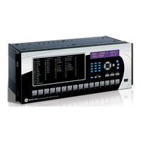
GE B90 UR Series Instruction Manual (478 pages)
Low Impedance Bus Differential System
Brand:
GE
| Category:
Control Unit
| Size: 11.78 MB
Table of Contents
Table of Contents
3
1 Getting Started
9
Important Procedures
9
Cautions and Warnings
9
Inspection Checklist
9
Ur Overview
10
Introduction to the Ur
10
Hardware Architecture
11
Ur Software Architecture
12
Important Ur Concepts
12
Enervista Ur Setup Software
13
Requirements
13
Software Installation
13
Configuring the B90 for Software Access
14
Using the Quick Connect Feature
17
Connecting to the B90 Relay
23
Ur Hardware
24
Mounting and Wiring
24
Communications
24
Faceplate Display
24
Using the Relay
25
Faceplate Keypad
25
Menu Navigation
25
Menu Hierarchy
25
Relay Activation
25
Relay Passwords
26
Flexlogic™ Customization
26
Commissioning
27
2 Product Description
29
Introduction
29
Overview
29
Ordering
35
Replacement Modules
37
Specifications
38
Protection Elements
38
User-Programmable Elements
39
Monitoring
40
Metering
41
Inputs
41
Power Supply
42
Outputs
42
Communications
43
Inter-Relay Communications
44
Environmental
44
Type Tests
45
Production Tests
45
Approvals
46
Maintenance
46
3 Hardware
47
Description
47
Panel Cutout
47
Module Withdrawal and Insertion
49
Rear Terminal Layout
50
Wiring
52
Typical Wiring
52
Dielectric Strength
58
Control Power
58
Ct and Vt Modules
59
Contact Inputs and Outputs
60
Rs232 Faceplate Port
68
Cpu Communication Ports
68
Irig-B
71
Direct Input/Output Communications
72
Description
72
Fiber: Led and Eled Transmitters
74
Fiber-Laser Transmitters
74
Interface
75
Rs422 Interface
78
Rs422 and Fiber Interface
80
And Fiber Interface
80
Ieee C37.94 Interface
81
C37.94Sm Interface
84
4 Human Interfaces
87
Enervista Ur Setup Software Interface
87
Introduction
87
Creating a Site List
87
Enervista Ur Setup Overview
87
Enervista Ur Setup Main Window
89
Extended Enervista Ur Setup Features
90
Settings Templates
90
Securing and Locking Flexlogic™ Equations
94
Settings File Traceability
96
Faceplate Interface
99
Faceplate
99
Led Indicators
100
Custom Labeling of Leds
102
Display
108
Keypad
108
Menus
108
Changing Settings
110
5 Settings
111
Overview
115
Settings Menu
115
Introduction to Elements
117
Product Setup
119
B90 Function
119
Security
119
Cybersentry Security
123
Display Properties
129
Clear Relay Records
130
Communications
131
Modbus User Map
153
Real Time Clock
153
User-Programmable Fault Report
158
Oscillography
159
User-Programmable Leds
161
User-Programmable Self Tests
164
Control Pushbuttons
164
User-Programmable Pushbuttons
166
Flex State Parameters
171
User-Definable Displays
172
Direct Inputs and Outputs
175
Installation
182
System Setup
183
Ac Inputs
183
Power System
184
Flexcurves
185
Bus
192
Flexlogic
194
Introduction to Flexlogic
194
Flexlogic Rules
200
Flexlogic Evaluation
200
Flexlogic Example
201
Flexlogic Equation Editor
205
Flexlogic Timers
205
Non-Volatile Latches
206
Grouped Elements
207
Overview
207
Setting Group
207
Bus Differential
207
Breaker Failure
207
Voltage Elements
207
Current Elements
207
End Fault Protection
207
Control Elements
231
Overview
231
Trip Bus 1
231
Setting Groups
233
Digital Elements
234
Monitoring Elements
237
Inputs/Outputs
241
Contact Inputs
241
5Virtual Inputs
243
Contact Outputs
244
Virtual Outputs
246
Remote Devices
247
Remote Inputs
248
Remote Double-Point Status Inputs
249
Remote Outputs
249
Resetting
250
Direct Inputs and Outputs
250
Iec 61850 Goose Analogs
254
Iec 61850 Goose Integers
255
Testing
256
Test Mode
256
Force Contact Inputs
257
Force Contact Outputs
258
6 Actual Values
259
Overview
259
Actual Values Main Menu
259
Status
259
Contact Inputs
261
Virtual Inputs
261
Remote Inputs
261
Remote Double-Point Status Inputs
262
Contact Outputs
262
Virtual Outputs
262
Remote Devices
263
Flex States
263
Ethernet
264
Real Time Clock Synchronizing
264
Iec 61850 Goose Integers
265
Direct Inputs
265
Direct Devices Status
266
Remaining Connection Status
266
Metering Conventions
267
Bus Zone
267
Currents
268
Voltages
268
Frequency
268
Iec 61580 Goose Analog Values
269
Records
270
User-Programmable Fault Reports
270
Event Records
270
Oscillography
270
Product Information
271
Model Information
271
Firmware Revisions
271
7 Commands and Targets
273
Commands
273
Commands Menu
273
Virtual Inputs
273
Clear Records
273
Set Date and Time
273
Relay Maintenance
275
Security
275
Targets Menu
277
Target Messages
277
Relay Self-Tests
277
8 Security
283
User Accounts
283
Overview
283
Enabling the Security Management System
283
Adding a New User
283
Modifying User Privileges
284
Cybersentry
286
Overview
286
Security Menu
288
9 Theory of Operation
293
Introduction
293
Bus Differential Protection
293
Dynamic Bus Replica Mechanism
294
Ct Ratio Matching
294
Differential Principle
295
Biased Differential Characteristic
295
Differential and Restraining Currents
296
Enhanced Security
297
Directional Principle
298
Current Directional Protection
298
Saturation Detector
299
Ct Saturation Detection
299
Output Logic and Examples
300
Output Logic
300
Internal and External Fault Example
300
10 Application of Settings
303
Overview
303
Introduction
303
Sample Busbar and Data
303
Zoning and Dynamic Bus Replica
305
North Bus Zone
305
South Bus Zone
305
Biased Characteristic Breakpoints
306
Description
306
High Breakpoint
306
Low Breakpoint
307
Slopes and High Set Threshold
309
External Faults on C-1
309
External Faults on C-2
309
External Faults on C-4
310
Bus Differential Settings
311
Description
311
Enhancing Relay Performance
312
Using Setting Groups
312
Parameter Lists
313
Flexanalog Items
313
A.1.1 Flexanalog Items
313
Flexinteger Items
315
A.1.2 Flexinteger Items
315
Modbus Communications
317
Modbus Rtu Protocol
317
Introduction
317
Physical Layer
317
Data Link Layer
317
B.1.1 Introduction
317
Algorithm
318
B.1.4 Crc-16 Algorithm
318
Modbus Function Codes
319
Supported Function Codes
319
Read Actual Values or Settings (Function Code 03/04H
319
Execute Operation (Function Code 05H
320
Store Single Setting (Function Code 06H
320
Store Multiple Settings (Function Code 10H
321
Exception Responses
321
File Transfers
322
Obtaining Relay Files Via Modbus
322
Modbus Password Operation
323
Memory Mapping
324
Modbus Memory Map
324
Data Formats
372
B.4.2 Data Formats
372
Iec 61850
407
Overview
407
Introduction
407
Communication Profiles
407
C.1.1 Introduction
407
Server Data Organization
408
Overview
408
Ggio1: Digital Status Values
408
Ggio2: Digital Control Values
408
Ggio4: Generic Analog Measured Values
408
C.2.1 Overview
408
Mmxn: Analog Measured Values
409
Protection and Other Logical Nodes
409
Server Features and Configuration
411
Buffered and Unbuffered Reporting
411
File Transfer
411
Timestamps and Scanning
411
Logical Device Name
411
Location
411
Logical Node Name Prefixes
412
Connection Timing
412
Non-Iec 61850 Data
412
Communication Software Utilities
412
Generic Substation Event Services: Gsse and Goose
413
Overview
413
Gsse Configuration
413
Fixed Goose
413
Configurable Goose
413
C.4.1 Overview
413
Ethernet Mac Address for Gsse/Goose
416
Gsse ID and Goose ID Settings
416
Iec 61850 Implementation Via Enervista Ur Setup
417
Overview
417
C.5.1 Overview
417
Configuring Iec 61850 Settings
418
About ICD Files
419
Creating an ICD File with Enervista Ur Setup
423
About Scd Files
423
Importing an Scd File with Enervista Ur Setup
426
Acsi Conformance
428
Acsi Basic Conformance Statement
428
Acsi Models Conformance Statement
428
Acsi Services Conformance Statement
429
Logical Nodes
432
Logical Nodes Table
432
Iec 60870-5-104
437
Interoperability Document
437
D.1.1 Interoperability Document
437
Iec 60870-5-104 Points
445
Device Profile Document
447
Dnp V3.00 Device Profile
447
E.1.2 Implementation Table
450
Dnp Point Lists
454
Binary Input Points
454
Binary and Control Relay Output
455
E.2.3 Analog Inputs
456
Miscellaneous
457
Change Notes
457
Revision History
457
Changes to the B90 Manual
457
F.1.1 Revision History
457
Abbreviations
468
Standard Abbreviations
468
F.2.1 Standard Abbreviations
468
Warranty
472
Ge Multilin Warranty
472
F.3.1 Ge Multilin Warranty
472
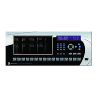
GE B90 UR Series Instruction Manual (474 pages)
UR Series Low Impedance Bus Differential System
Brand:
GE
| Category:
Relays
| Size: 8.98 MB
Table of Contents
Table of Contents
3
1 Getting Started
11
Important Procedures
11
Cautions and Warnings
11
Inspection Procedure
12
Ur Overview
13
Introduction to the Ur
13
Hardware Architecture
14
Ur Software Architecture
15
Important Ur Concepts
15
Enervista Ur Setup Software
16
Requirements
16
Software Installation
16
Configuring the B90 for Software Access
17
Using the Quick Connect Feature
20
Connecting to the B90 Relay
26
Ur Hardware
27
Mounting and Wiring
27
Communications
27
Faceplate Display
27
Using the Relay
28
Faceplate Keypad
28
Menu Navigation
28
Menu Hierarchy
28
Relay Activation
28
Relay Passwords
29
Flexlogic™ Customization
29
Commissioning
30
2 Product Description
31
Introduction
31
Overview
31
Ordering
39
Replacement Modules
41
Specifications
42
Protection Elements
42
User-Programmable Elements
43
Monitoring
43
Metering
44
Inputs
44
Power Supply
45
Outputs
45
Communication Protocols
46
Inter-Relay Communications
47
Environmental
47
Type Tests
48
Production Tests
48
Approvals
49
Maintenance
49
3 Hardware
51
Description
51
Panel Cutout
51
Rear Terminal Layout
53
Wiring
54
Typical Wiring
54
Dielectric Strength
60
Control Power
60
Ct and Vt Modules
61
Contact Inputs and Outputs
62
Rs232 Faceplate Port
70
Cpu Communication Ports
70
Irig-B
73
Direct Input/Output Communications
75
Description
75
Fiber: Led and Eled Transmitters
77
Fiber-Laser Transmitters
77
Interface
79
Rs422 Interface
82
Rs422 and Fiber Interface
84
And Fiber Interface
84
Ieee C37.94 Interface
85
C37.94Sm Interface
89
4 Human Interfaces
93
Enervista Ur Setup Software Interface
93
Introduction
93
Creating a Site List
93
Enervista Ur Setup Overview
93
Enervista Ur Setup Main Window
95
Extended Enervista Ur Setup Features
97
Settings Templates
97
Securing and Locking Flexlogic™ Equations
101
Settings File Traceability
103
Faceplate Interface
106
Faceplate
106
Led Indicators
107
Custom Labeling of Leds
110
Display
114
Keypad
114
Menus
114
Changing Settings
116
5 Settings
117
Overview
121
Settings Menu
121
Introduction to Elements
123
Product Setup
125
B90 Function
125
Security
125
Display Properties
130
Clear Relay Records
131
Communications
132
Modbus User Map
153
Real Time Clock
153
User-Programmable Fault Report
154
Oscillography
155
User-Programmable Leds
157
User-Programmable Self Tests
161
Control Pushbuttons
161
User-Programmable Pushbuttons
163
Flex State Parameters
169
User-Definable Displays
169
Direct Inputs and Outputs
172
Installation
179
System Setup
180
Ac Inputs
180
Power System
181
Flexcurves
182
Bus
189
Flexlogic
191
Introduction to Flexlogic
191
Flexlogic™ Rules
197
Flexlogic™ Example
198
Flexlogic™ Equation Editor
202
Non-Volatile Latches
203
Overview
204
Bus Differential
205
Breaker Failure
209
Voltage Elements
217
Current Elements
218
End Fault Protection
225
Overview
228
Setting Groups
230
Digital Elements
231
Monitoring Elements
234
Contact Inputs
238
Virtual Inputs
240
Contact Outputs
241
Virtual Outputs
243
Remote Devices
244
Remote Inputs
245
Remote Double-Point Status Inputs
246
Resetting
247
Direct Inputs and Outputs
248
Iec 61850 Goose Analogs
251
Iec 61850 Goose Integers
252
Test Mode
253
Force Contact Inputs
254
Force Contact Outputs
255
Actual Values Menu
257
Contact Inputs
259
Remote Double-Point Status Inputs
260
Remote Devices
261
Ethernet
262
Direct Inputs
263
Metering Conventions
264
Currents
265
Iec 61580 Goose Analog Values
266
User-Programmable Fault Reports
267
Model Information
269
Commands Menu
271
Clear Records
272
Relay Maintenance
273
Targets Menu
274
Overview
279
Password Security Menu
280
Remote Passwords
281
Access Supervision
282
Overview
284
Modifying User Privileges
285
Bus Differential Protection
287
Dynamic Bus Replica Mechanism
288
Biased Differential Characteristic
289
Differential and Restraining Currents
290
Enhanced Security
291
Current Directional Protection
292
Ct Saturation Detection
294
Output Logic
296
Introduction
299
North Bus Zone
301
Description
302
Low Breakpoint
303
Description
304
External Faults on C-2
306
External Faults on C-4
307
Description
308
Using Setting Groups
309
Replace a Module
311
Replace Battery
313
Dispose of Battery
314
Uninstall and Clear Files and Data
317
Repairs
318
Storage
319
Disposal
320
A.1.1 Flexanalog Items
321
A.1.2 Flexinteger Items
323
B.1.1 Introduction
325
B.1.4 Modbus Rtu Crc-16 Algorithm
326
B.2.1 Supported Function Codes
328
B.2.3 Execute Operation (Function Code 05H)
329
B.2.5 Store Multiple Settings (Function Code 10H)
330
B.3.1 Obtaining Relay Files Via Modbus
331
B.4.1 Modbus Memory Map
333
B.4.2 Data Formats
377
C.1.1 Introduction
409
C.1.3 File Transfer by Iec 61850
410
C.2.1 Overview
411
C.2.6 Mmxn: Analog Measured Values
412
C.3.1 Buffered and Unbuffered Reporting
414
C.3.6 Logical Node Name Prefixes
415
C.4.1 Overview
416
C.4.5 Ethernet Mac Address for Gsse/Goose
418
C.4.6 Gsse ID and Goose ID Settings
419
C.5.1 Overview
420
C.5.2 Configuring Iec 61850 Settings
421
C.5.3 about ICD Files
422
C.5.4 Creating an ICD File with Enervista Ur Setup
426
C.5.6 Importing an Scd File with Enervista Ur Setup
429
C.6.1 Acsi Basic Conformance Statement
431
C.6.3 Acsi Services Conformance Statement
432
C.7.1 Logical Nodes Table
435
D.1.1 Interoperability Document
439
D.1.2 Iec 60870-5-104 Points
447
E.1.1 Dnp V3.00 Device Profile
449
E.1.2 Implementation Table
452
E.2.1 Binary Input Points
456
E.2.2 Binary and Control Relay Output
457
E.2.3 Analog Inputs
458
F.1.1 Revision History
459
F.2.1 Standard Abbreviations
463
F.3.1 Ge Multilin Warranty
465
Related Products
GE Becker 3.5M Series
GE Intellix BMT 330
GE Series 0
GE Series 00
GE Series 0-Mate
GE B90
GE BSS25JSTGSS and
GE Monogram BCS42EL
GE Bottom-Drawer
GE BioProcess LPLC
GE Categories
Refrigerator
Ranges
Microwave Oven
Air Conditioner
Dishwasher
More GE Manuals