beautypg.com
Manuals
Brands
GE Manuals
Medical Equipment
5498522
GE 5498522 Manuals
Manuals and User Guides for GE 5498522. We have
1
GE 5498522 manual available for free PDF download: Basic Service Manual
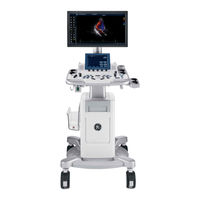
GE 5498522 Basic Service Manual (289 pages)
Brand:
GE
| Category:
Medical Equipment
| Size: 17.74 MB
Table of Contents
Certified Electrical Contractor Statement - for USA Only
13
Damage in Transportation
13
Omission and Errors
14
Service Safety Considerations
15
Legal Notes
16
Trademarks
16
Table of Contents
17
Chapter 1 - Introduction
25
Overview
26
Contents in this Chapter
26
Manual Overview
27
Contents in this Manual
27
Overview
27
Typical Users of the Proprietary Service Manual
28
VIVID T8/ VIVID T8 Pro Models Covered by this Manual
29
Important Conventions
30
Conventions Used in Book
30
Standard Hazard Icons
32
Product Icons
34
Labels Locations
35
Safety Considerations
36
Contents in this Section
36
Introduction
36
Human Safety
36
Mechanical Safety
39
Electrical Safety
42
Dangerous Procedure Warnings
44
Lockout/Tagout (LOTO) Requirements
45
Returning Probes and Repair Parts
46
EMC, EMI and ESD
47
What Is EMC
47
CE Compliance
47
Electrostatic Discharge (ESD) Prevention
48
Customer Assistance
49
Contact Information
49
Phone Numbers for Customer Assistance
50
System Manufacturer
50
Authorized Representative
51
Chapter 2 - Site Preparations
53
Contents in this Chapter
54
General Ultrasound System Requirements
55
Contents in this Section
55
Ultrasound System Environmental Requirements
55
Electrical Requirements
58
EMI Limitations
61
Probes Environmental Requirements
63
Time and Manpower Requirements
63
Facility Needs
64
Contents in this Section
64
Purchaser Responsibilities
65
Required Facility Needs
66
Desirable Features
67
Minimal Floor Plan Suggestion
68
Recommended Floor Plan Suggestion
69
Suggested Floor Plan, Ultrasound System, and Echopac PC in same Room
70
Networking Setup Requirements
70
Environmental Dangers
74
Patient Vicinity UL60601-1 (USA)
74
Patient Environment IEC60601-1 and ANSI AAMI ES60601-1
75
Chapter 3 - System Setup
77
Overview
78
Contents in this Chapter
78
Setup Reminders
79
Average Setup Time
79
Setup Warnings
79
Receiving and Unpacking the Equipment
82
Purpose of this Section
82
Contents in this Section
82
Warnings for Receiving and Unpacking
82
The Tilt Indicator
83
Receiving the VIVID T8/ VIVID T8 Pro
83
Unpacking the VIVID T8/ VIVID T8 Pro
88
Packing the Equipment
92
Packing Materials - Recycling Information
93
Preparing for Setup
94
Verify Customer Order
94
Physical Inspection
94
EMI Protection
94
Completing the Setup
95
Purpose of this Section
95
Contents in this Section
95
System Specifications
95
Electrical Specifications
96
Connections on the I/O Rear Panel
97
Connecting Probes
97
Powering the System
97
System Configuration
98
Purpose of this Section
98
Contents in this Section
98
VIVID T8/ VIVID T8 Pro Configuration
98
Peripherals Installation
99
Overview
99
Furnished Materials
100
Peripherals Installation Instructions
102
Connectivity Setup
114
TCP/IP Screen
114
Network Setup
116
Setup Connection to a DICOM Server
116
Dicom Sr
127
Export Configuration
129
Create a New Dataflow
136
Query/Retrieve Setup
141
Option Setup
145
Software Option Installation Procedure
145
Paperwork after Setup
147
Contents in this Section
147
User's Manual(S)
147
Product Locator Installation Card
148
Chapter 4 - General Procedures and Functional Checks
149
Purpose of this Chapter
150
Contents in this Chapter
150
Special Equipment Required
150
General Procedures
151
Overview
152
Power On/Boot up
153
Power off
156
LCD Monitor Position Adjustment
157
Logging on to VIVID T8/ VIVID T8 Pro as "ADM
158
Removable Media
159
Archiving and Loading Presets
160
Data Management
162
Backup
162
Installation and Setup Procedure for Peripherals
162
Where Are the User Manuals and the Service Manual
163
How to Display or Print the PDF Files from the Manual CD
163
Cleaning the Trackball
164
Functional Checks
166
Overview
166
Preparation
166
Basic Controls
167
Operator Panel
167
Touch Panel
168
Performance Tests
168
2D Mode (B Mode) Checks
169
2D Mode Screen Example
169
Preparations
169
Adjust the 2D Mode Controls
169
M Mode Checks
170
M-Mode Screen Example
170
Preparations
170
Adjust the M Mode Controls
170
Color Mode Checks
171
Select Color 2D Mode
171
Adjust the Color 2D Mode Controls
172
Select Color M Mode
173
PW/CW Doppler Mode Checks
175
Adjust the PW/CW Doppler Mode Controls
176
Tissue Velocity Imaging (TVI) Checks
177
Adjust the TVI Controls
178
Basic Measurements
178
Probe/Connectors Check
179
ECG Check
180
Cineloop Check
181
Preparation
181
Adjust the Cineloop Controls
181
Back End Processor Checks
182
Operator Panel Test
182
Peripheral Checks
182
Turn off Power to VIVID T8/ VIVID T8 Pro
182
Mechanical Functions Checks
182
Power Supply Test & Adjustments
184
Power Supply Test Procedure
184
Power Supply Adjustment
184
Application Turnover Check List
185
Software Configuration Checks
185
Site Log
186
Chapter 5 - Components and Functions (Theory)
187
Contents in this Chapter
188
Block Diagram and Theory
189
General Information
189
Top Console
189
Block Diagram
190
Power Diagram
192
Overview
192
AC Power
192
Common Service Platform
193
Introduction
193
Chapter 6 - Service Adjustments
195
Contents in this Chapter
196
LCD Monitor Adjustments
197
Purpose of this Section
197
Monitor Adjustments
197
Chapter 7 - Diagnostics/Troubleshooting
199
Contents in this Chapter
200
Gathering Trouble Data
201
Overview
201
Collect Vital System Information
201
Collect a Trouble Image with Logs
202
Screen Capture
203
Check and Record the P2 Key Function
204
Setting the P2 Key to Screen Capture
205
Capturing a Screen
206
Reset the P1 Key to Customer's Functionality
208
Common Diagnostics
209
Utilities
209
Network Configuration
210
Chapter 8 - Replacement Procedures
217
Contents in this Chapter
218
Warnings and Important Information
219
Warnings
219
Returning/Shipping Probes and Repair Parts
220
Disassembly/Re-Assembly
221
Warning and Caution
221
Tools Needed for Servicing VIVID T8/ VIVID T8 Pro
222
Overview of VIVID T8/ VIVID T8 Pro
223
Cleaning the Trackball
225
Cleaning the Air Filter
227
Loading the Software
229
Purpose of this Section
229
Customer Provided Prerequisite
229
Data Management - Moving All Images
229
Backing up the Patient Archive and System Configurations
230
Restoring up the Patient Archive and System Configurations
230
Recording Important Settings and Parameters
230
Loading the System Software
231
Chapter 9 - Renewal Parts
239
Contents in this Chapter
240
List of Abbreviations
241
Renewal Parts Lists
242
AC Power Cord
242
Operator Console Assy
243
Accessories and Cable Kits
244
Probe
244
Peripheral
245
Power Cord
246
Manuals
247
Chapter 10 - Care and Maintenance
249
Contents in this Chapter
250
Warnings
251
Why Do Maintenance
252
Periodic Maintenance Inspections
252
Keeping Records
252
Quality Assurance
253
Maintenance Task Schedule
254
How Often Should Maintenance Tasks be Performed
254
Tools Required
256
Standard GE Tool Kit
256
GE-2 Tool Kit
258
Special Tools, Supplies and Equipment Used for Maintenance
259
System Maintenance
260
Preliminary Checks
260
Functional Checks
261
Physical Inspection
263
Optional Diagnostic Checks
264
Probe Maintenance
265
Electrical Safety Tests
267
Safety Test Overview
267
Leakage Current Limits
269
Outlet Test - Wiring Arrangement
271
Grounding Continuity
272
Chassis Leakage Current Test
273
Probe Leakage Current Test
275
When There's too Much Leakage Current
278
AC/DC Fails
278
Chassis Fails
278
Probe Fails
279
Peripheral Fails
279
Still Fails
279
New Unit
279
ECG Fails
279
Inspection Paperwork
280
Electrical Safety Tests Log
282
Related Products
GE 5498519
GE 5498521
GE 5498524
GE 5498523
GE 5498957
GE 5499582
GE 5430949
GE 5435028
GE 5411382
GE 5478041
GE Categories
Refrigerator
Ranges
Microwave Oven
Air Conditioner
Dishwasher
More GE Manuals