beautypg.com
Manuals
Brands
Gardner Denver Manuals
Air Compressor
SAV75-100G2A
Gardner Denver SAV75-100G2A Manuals
Manuals and User Guides for Gardner Denver SAV75-100G2A. We have
1
Gardner Denver SAV75-100G2A manual available for free PDF download: Operating And Service Manual
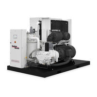
Gardner Denver SAV75-100G2A Operating And Service Manual (100 pages)
Brand:
Gardner Denver
| Category:
Air Compressor
| Size: 3.96 MB
Table of Contents
Support Services
2
Instructions for Ordering Repair Parts/Remanufactured Airends
2
Warning - Prohibition - Mandatory Label Information
3
Safety Precautions
5
Table of Contents
6
Index
7
List of Illustrations
8
Section 1, General Information
9
Air Flow in the Compressor System
9
Compression Principle
9
Compressor
9
Figure 1-1 - Compression Cycle
9
Cooling, Sealing and Lubrication
10
Figure 1-2 - Starter Box
10
Figure 1-3 - Control Box
10
Figure 1-4 - Compressor / Motor Side
11
Figure 1-5 - Cooler / Reservoir Side
11
Figure 1-6 - Air/Oil Flow Diagram
12
Section 2, Installation
13
Lifting Unit
13
Location
13
Air-Cooled Units, Location
14
Air-Cooled Units
14
Figure 2-1 - Typical Compressor Room
14
Figure 2-2 - Air Flow Chart
14
Foundation
15
Water-Cooled Units
15
Drain
15
Cold Weather Operation
16
Cold Weather Operation, Installation for
16
Installation for Cold Weather Operation
16
Figure 2-3 - Cold Weather Installation
16
Auxiliary Air Receiver
17
Control Piping
17
Inlet Line
17
Moisture Separator/Trap
17
Figure 2-4 - Inlet Line Lengths
17
Blowdown Valve Piping
18
Figure 2 5 - Heat Exchanger (Oil Cooler) Approximate Water Flow
18
Water Piping
19
Figure 2-6 - Aftercooler Approximate Water Flow
19
Water Piping (Series)
20
Figure 2-7 - Series Piping
20
Figure 2-8 - Parallel Piping
20
Electrical Wiring
21
Grounding
21
Water Piping (Parallel)
21
Lubrication Motor
22
Section 3, Starting & Operating Procedures
23
Prestart-Up Instructions
23
Daily Check
25
Starting the Unit
25
Unit Cold
25
Unit Hot
25
Stopping the Unit
25
Quick Start Guide (Controller)
26
Section 4, Controls & Instrumentation
34
Controls & Instrumentation Airsmart G2 Controller Operation
34
General Description
34
Figure 4-1 - Controller Keypad
34
Figure 4- 2- Schematic Tubing Diagram
35
Blowdown Valve
36
Minimum Discharge Pressure Valve
36
Figure 4- 3- Minimum Discharge Pressure/Check Valve
36
Inlet Valve
37
Pressure Regulator
37
Shuttle Valve
37
Solenoid Valves IVC and IVO
37
Air Filter Vacuum Switch
38
Plant Delivery
38
Reservoir
38
Separator
38
Figure 4-4 -Turn Valve - Electra Saver Only
38
Emergency Stop Push-Button
39
Temperature Sensor Discharge
39
Separator
39
Fan Starter
40
Fuse Blocks
40
Main Starter
40
Power Supply
40
Terminal Strip
40
Figure 4- 5- Compressor Package P&ID
42
Figure 4- 6- Compressor Package Control Component States
43
Figure 4- 7- Electra Saver Wiring Diagrams
44
Figure 4- 8- Electra Saver II Wiring Diagrams
44
Figure 4- 9- Wiring Diagram - WYE DELTA (AIR-COOLED / WATER-COOLED)
45
Figure 4- 10- Wiring Diagram - WYE DELTA (AIR-COOLED / WATER-COOLED)
54
Section 5, Lubrication, Oil Cooler, Oil Filter & Separator
67
Lubricant Recommended
67
Oil Specifications
67
Oil System Compressor
67
High Temperature Operation
68
Moisture in the Oil System
68
Figure 5-1 - Dew Point Chart F
69
Figure 5-2 - Dew Point Chart C
69
Figure 5-3 - Flow Diagram - Air/Oil System
70
Figure 5-4 - Oil Flow Diagram - Remote Overhead Mounted Cooler
71
Remote Mounted Elevated Cooler Assembly
72
Heat Exchanger (Oil) Piping
73
Addition of Oil between Changes
75
Cold Ambient Operation
75
Lubricant Change Procedure
75
Oil Change Interval
76
Oil Level Gauge
76
Figure 5-5 - Oil Level Gauge
76
Oil Sampling Valve
77
Figure 5-6 - Oil Change Interval
77
Figure 5-7 - Oil Sampling Valve Location
77
Draining and Cleaning
78
Filling
79
Figure 5-8 - Approximate Oil System Capacities
79
Oil Filter
80
Compressor Oil Cooler - Water-Cooled Heat Exchanger
81
Oil Cooler - Radiator Type
81
Thermal Control (Thermostatic Mixing) Valve
81
Figure 5-9 - Thermostatic Mixing Valve Element
81
Figure 5-10 - Water Control Valve
82
Water Flow Control Valve for Heat Exchanger
83
Oil Reservoir
84
Oil Separator Compressor (GD Eliminator)
84
Oil Carryover
84
Water Shutoff Valve - Water-Cooled Heat Exchanger
84
Figure 5-11 - Oil Separator
84
Inspection
85
Pressure Differential Gauging
85
Removal for Inspection or Replacement
86
Oil System Check
86
Air and Oil Discharge Temperature
86
Oil Inlet Pressure
86
Oil Inlet Temperature
86
Oil Cooler Oil Pressure Differential (Air-Cooled Radiator)
87
Oil Cooler Oil Pressure Differential (Water-Cooled Heat Exchanger)
87
Oil Cooler Temperature Differential (Air-Cooled Radiator)
87
Oil Cooler Temperature Differential (Water-Cooled Heat Exchanger)
87
Oil Cooler Water Pressure Differential (Water-Cooled Heat Exchanger)
87
Section 6, Air Filter
88
Air Filter, Heavy Duty (Standard)
88
Filter Element
88
Figure 6-1 - Heavy Duty Air Filter
88
Air Filter Element Life
89
Inlet Tube
89
Section 7, Coupling
90
Coupling
90
Figure 7-1 - Installation of Coupling Cushions
90
Figure 7-2 - Installation of Coupling Cushions
91
Section 8, Maintenance Schedule
93
Service Check List
93
Every 1000 Hours Operation
93
Every 125 Hours Operation
93
Every 8 Hours Operation
93
Every 2000 Hours Operation
93
Service Check List
94
Section 9, Troubleshooting
96
Related Products
Gardner Denver Wittig SLS 34
Gardner Denver Wittig SLS 54
Gardner Denver ST75-100G2A
Gardner Denver SAVG2-75
Gardner Denver STG2-75
Gardner Denver SAVG2-100
Gardner Denver STG2-100
Gardner Denver SAVG2-125
Gardner Denver SAVG2-150
Gardner Denver Mako SSCFS2
Gardner Denver Categories
Air Compressor
Water Pump
Dehumidifier
Controller
Blower
More Gardner Denver Manuals