beautypg.com
Manuals
Brands
Fujitsu Manuals
Computer Hardware
FR60 Lite MB91F267N
Fujitsu FR60 Lite MB91F267N Manuals
Manuals and User Guides for Fujitsu FR60 Lite MB91F267N. We have
1
Fujitsu FR60 Lite MB91F267N manual available for free PDF download: User Manual
Fujitsu FR60 Lite MB91F267N User Manual (104 pages)
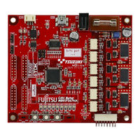
32-BIT MICROCONTROLLER bits pot red CAN motor board
Brand:
Fujitsu
| Category:
Computer Hardware
| Size: 2.49 MB
Table of Contents
Revision History
2
Note
3
Table of Contents
4
Introduction
10
Contact
11
Suppliers of the Parts/Materials
12
1 Setting up the Starter Kit
13
Table 1-1 Component List
13
Figure 1-1 External Board View
14
Table 1-2 Description of the Respective Board Parts
15
Figure 1-2 System Connection Diagram
16
Table 1-3 MB91F267N Pin Assignment
17
Setting up the PC
19
Downloading the Software
20
Installing a USB Driver
20
Figure 1-3 Downloading the USB Driver
20
Figure 1-4 Installing FT232R USB UART
21
Figure 1-5 Selecting the Search Locations
22
Figure 1-6 Completing the USB Serial Converter Installation
22
Figure 1-7 Installing USB Serial Port
23
Figure 1-8 Selecting the Search Locations
23
Figure 1-9 Completing the USB Serial Port Installation
24
Installing the Integrated Development Environment SOFTUNE (Bits Pot Dedicated Version)
25
Figure 1-10 SOFTUNE Setup Confirmation
25
Figure 1-11 Starting SOFTUNE Setup
25
Figure 1-12 Caution on SOFTUNE Setup
26
Figure 1-13 SOFTUNE Setup/License Agreement
26
Figure 1-14 SOFTUNE Setup/Version Information
27
Figure 1-15 SOFTUNE Setup/Selecting the Destination of Installation
27
Figure 1-16 SOFTUNE Setup/Selecting the Components
28
Figure 1-17 SOFTUNE Setup/Confirming the Installation Settings
28
Figure 1-18 SOFTUNE Setup/Completion
29
Installing PC Writer (Bits Pot Red Dedicated Version)
30
Figure 1-19 PC Writer/Installation Dialog
30
Figure 1-20 PC Writer/Setup Type
31
Figure 1-21 PC Writer/Ready to Install
31
Figure 1-22 Completing the PC Writer Installation
32
Configuring the Evaluation Board and Connecting It to the PC
33
Figure 1-23 MODE Selection
33
Figure 1-24 Connection between the PC and the Board
34
2 Running the Program
35
Executing in Single Chip Mode
36
Building a Project
36
Figure 2-1 Opening a Workspace
36
Figure 2-2 Selecting a Workspace
37
Figure 2-3 Building a Project
37
Writing the Program into the Microcontroller
38
Figure 2-4 Completing the Build
38
Figure 2-5 Opening the File to Write
38
Figure 2-6 Selecting the File to Write
39
Figure 2-7 Select the COM Port to be Used for the Writing
40
Figure 2-8 Checking the COM Port
41
Figure 2-9 Writing the Program
42
Figure 2-10 Completing the Program Writing
42
Debugging by Using Monitor Debugger
43
Writing Monitor Debugger into the Microcontroller
43
Figure 2-11 Opening the File to Write
43
Figure 2-12 Selecting the File to Write
44
Figure 2-13 Select the COM Port to be Used for the Writing
45
Figure 2-14 Checking the COM Port
46
Figure 2-15 Writing the Program
47
Figure 2-16 Completing the Program Writing
47
Activating SOFTUNE and Configuring the Debug Settings
48
Figure 2-17 Opening a Workspace
48
Figure 2-18 Selecting a Workspace
49
Figure 2-19 Building a Project
49
Figure 2-20 Completing the Build
50
Figure 2-21 Changing the Debug Settings
50
Figure 2-22 Starting the Debug Setting Wizard
51
Figure 2-23 Selecting the Debugger Type
51
Figure 2-24 Selecting the Device Type
52
Figure 2-25 Specifying a Batch File
52
Figure 2-26 Configuring the Target File Settings
53
Figure 2-27 Setting Setup File Selection
53
Figure 2-28 Completing the Setup Wizard
54
Figure 2-29 Start Debugging
54
Writing the Program into the Microcontroller
55
Figure 2-30 Showing the Commands Window
55
Figure 2-31 Inputting Commands
56
Figure 2-32 Completing the Program Writing
56
Loading the Target File
57
Figure 2-33 Loading the Target File
57
Running the Debugger
58
Figure 2-34 Setting Break Points
58
Figure 2-35 Running the Program
58
Notes on Monitor Debugger
59
Figure 2-36 Stopping the Program
59
3 Operation of the Sample Program
60
Bits Pot Red Single-Unit Operation
61
Figure 3-1 Single-Unit Operation/Controls and Mechanicals
61
Table 3-1 Single-Unit Operation/Descriptions of the Controls and Mechanicals
61
CAN Communication Operation (CAN Communication Operation with the Bits Pot White)
63
Figure 3-2 CAN Communication Operation/Controls and Mechanicals
63
Table 3-2 CAN Communication Operation/Descriptions of the Controls and Mechanicals
64
4 Try to Rotate the BLDC Motor
65
What Is the BLDC Motor
65
Figure 4-1 DC Motor/Bldc Motor Configuration Examples
65
How Does the BLDC Motor Rotate
66
Figure 4-2 Names of the Respective Elements
66
Figure 4-3 120° Conduction Method Time Chart
67
BLDC Motor Rotation Control by the Microcontroller
68
Figure 4-4 Motor Driver Circuit
68
Figure 4-5 Timer Control Registers
69
Table 4-1 Microcontroller Pin/Motor Driver Circuit Connections
69
Table 4-2 Functions Employed by the Motor Driving Macro
69
Table 4-3 Description of the Timer Control Registers and Setting Values
70
Figure 4-6 Output Compare Registers
71
Table 4-4 Description of the Output Compare Registers and Setting Values
72
Figure 4-7 Operation of the Free-Run Timer
73
Table 4-5 Correspondence between the Output Compare Values and the Switchings
73
Figure 4-8 U-High Output to Output Comparisons
74
Understanding and Running the Program for the BLDC Motor Operation
75
Figure 4-9 Motor Operation Flowchart
75
Figure 4-10 Operation Mode Settings
76
Figure 4-11 Main Function
76
Figure 4-12 SW2 Interrupt
77
Figure 4-13 Free-Run Timer Interrupt
77
Handling Controls of the BLDC Motor
78
Figure 4-14 Motor Controls Flowchart
78
Figure 4-15 Rotation Speed Control
79
Figure 4-16 Brake Control
80
Figure 4-17 Rotation Direction Control
81
5 Try to Use CAN Communication
82
What Is CAN
82
Figure 5-1 Example of On-Board CAN Application
82
Figure 5-2 CAN Bus Signal Levels
83
CAN Specifications
84
CAN Frame Configurations
84
Figure 5-3 CAN Frame Configurations
85
Arbitration
88
Figure 5-4 Operation of the Arbitration
88
Figure 5-5 Example of Arbitration Among Nodes
89
Error Management
90
Table 5-1 Description of the Error Types
90
Figure 5-6 CAN Status Transition
91
CAN Communication by Using the Microcontroller
92
Figure 5-7 CAN Circuit
92
Figure 5-8 Entire CAN Communication Control Register
93
Table 5-2 Description of the Entire CAN Communication Control Registers and Setting Values
94
Understanding and Running the Program for CAN Communication
95
CAN Communication Configuration
95
Table 5-3 CAN Communication Conditions of the Sample Program
95
Table 5-4 CAN Message Ids in the Sample Program
96
Sample Program Sequence
99
Figure 5-9 CAN Communication Flowchart
99
Figure 5-10 Operation Mode Settings
100
Figure 5-11 Main Function
100
Figure 5-12 CAN Timer Interrupt Control
101
Figure 5-13 Motor Rotation Information Transmit
102
Figure 5-14 Temperature Sensor Information Transmit
102
Figure 5-15 CAN Receive Processing
103
6 Appendix
104
Sample Program Folder/File Configuration
104
Table 6-1 Sample Program Folder/File Configuration
104
Related Products
Fujitsu MB91F109 FR30
Fujitsu MB91460 SERIES FR60
Fujitsu MB91460 SERIES
Fujitsu MB91F109
Fujitsu MB9B300A Series
Fujitsu MB9B400A Series
Fujitsu MB90360 series
Fujitsu MB9BF505NB
Fujitsu MB9BF305RB
Fujitsu MB9BF306RB
Fujitsu Categories
Air Conditioner
Laptop
Server
Scanner
Storage
More Fujitsu Manuals