Emerson Unidrive M400 Manuals
Manuals and User Guides for Emerson Unidrive M400. We have 8 Emerson Unidrive M400 manuals available for free PDF download: User Manual, Installation Manual, Installation And Commissioning Manual, Quick Start Quide, Quick Start Manual
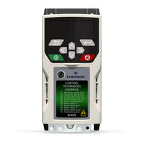
Emerson Unidrive M400 User Manual (198 pages)
Variable Speed AC drive for induction
motors
Brand: Emerson
|
Category: Controller
|
Size: 10.58 MB
Table of Contents
-
-
-
-
Menu 2: Ramps102
-
Trip Indications172
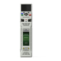
Emerson Unidrive M400 User Manual (198 pages)
Si-Ethernet and Unidrive M - Onboard Ethernet
Table of Contents
-
-
Parameters
38-
Menus38
-
-
-
Modbus TCP/IP119
-
-
(Lsb)124
-
Transaction ID126
-
Ethernet/Ip144
-
-
Ctscope180
-
Syptpro180
-
CT OPC Server181
-
Security
182 -
Diagnostics
183 -
-
Issue Number194
-
-

Emerson Unidrive M400 User Manual (166 pages)
Variable Speed AC drive for induction motors
Table of Contents
-
-
Introduction11
-
Model Number11
-
Ratings12
-
Options15
-
-
-
-
12 Diagnostics
137
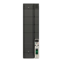
Emerson Unidrive M400 Installation Manual (120 pages)
Unidrive HS series;
Unidrive M series.
Frame 7 to 10
Brand: Emerson
|
Category: Controller
|
Size: 11.84 MB
Table of Contents
-
-
Introduction11
-
Model Number11
-
Ratings13
-
-
-
-
-
Mounting116
-
Environment116
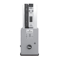
Emerson Unidrive M400 Installation And Commissioning Manual (40 pages)
Electronic Bypass Controller
Brand: Emerson
|
Category: Controller
|
Size: 2.45 MB
Table of Contents
-
-
Inspection14
-
-
-
-
TEST Mode26
-
Bypass Mode27
-
Hand Mode27
-
VFD Mode27
-
Auto Mode28

Emerson Unidrive M400 Quick Start Quide (36 pages)
Frame sizes 1 to 4 Manufacturing Automation drive Fast set-up and diagnosis with real-text display, plus integrated CODESYS based PLC
Table of Contents
-
-
Ratings7
-

Emerson Unidrive M400 Quick Start Manual (16 pages)
Supervisory Controller Setup with VFD Drive
Brand: Emerson
|
Category: Controller
|
Size: 3.32 MB
