beautypg.com
Manuals
Brands
Emerson Manuals
Industrial Equipment
PACSystems VersaSafe IC220SDL963
Emerson PACSystems VersaSafe IC220SDL963 Manuals
Manuals and User Guides for Emerson PACSystems VersaSafe IC220SDL963. We have
1
Emerson PACSystems VersaSafe IC220SDL963 manual available for free PDF download: User Manual
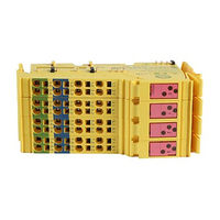
Emerson PACSystems VersaSafe IC220SDL963 User Manual (111 pages)
ENHANCED SAFETY LOGIC MODULE, SAFE OUTPUT 24VDC, 8 POINTS
Brand:
Emerson
| Category:
Industrial Equipment
| Size: 3.1 MB
Table of Contents
Table of Contents
2
Chapter 1: For Your Safety
7
General Safety Notes
7
Electrical Safety
8
Safety of the Machine or System
9
Safety When Starting Applications
10
Directives and Standards
11
Correct Usage
11
Documentation
12
Abbreviations Used
12
Chapter 2: Product Description
13
Note about the System Description
13
Brief Description of the Safety Module
13
Structure of the Safety Module
14
Housing Dimensions
15
Connection Options for Actuators Depending on the Parameterization
18
Local Diagnostic and Status Indicators
18
Safe State
20
Operating State
20
Error Detection in I/O Devices
20
Device Errors
21
Parameterization Errors
22
Process Data Words
22
Programming Data/Configuration Data
22
Local Bus
22
Other Bus Systems or Networks
22
Chapter 3: Versapoint Potential and Data Routing, and Versapoint Connectors
23
Versapoint Potential and Data Routing
23
Supply Voltage UL
23
Supply Voltage U
23
Supply Voltage U
24
Terminal Point Assignment
25
Chapter 4: Assembly, Removal, and Electrical Installation
28
Assembly and Removal
28
Unpacking the Module
28
General
28
Setting the DIP Switches
29
Assembly and Removal of the Safety Module
30
Electrical Installation
33
Electrical Installation of the Versapoint Station
33
Electrical Installation of the Safety Module
34
Chapter 5: Parameterization of the Safety Module
36
Parameterization of the Safety Module in a Versasafe System
36
Parameterization of the Safe Outputs
37
Behavior of the Outputs in the Event of Enabled Switch-Off Delay for Stop Category 1
39
Chapter 6: Connection Examples for Safe Outputs
41
Explanation of the Examples
41
Notes on the Protective Circuit for External Re- Lays/Contactors (Freewheeling Circuit)
42
Measures Required to Achieve a Specific Safety Integrity Level
43
Single-Channel Assignment of Safe Outputs
45
Two-Channel Assignment of Safe Outputs
48
Chapter 7: Startup and Validation
52
Initial Startup
52
Restart after Replacing a Safety Module
54
Replacing a Safety Module
54
Restart
54
Validation
54
Chapter 8: Errors: Messages and Removal
56
Safe Digital Output Errors
57
Supply Voltage Errors
58
General Errors
59
Parameterization Errors
59
Connection Errors to Satellites
61
Acknowledging an Error
61
Chapter 9: Maintenance, Repair, Decommissioning, and Disposal
63
Maintenance
63
Repair
63
Chapter 10: Technical Data and Ordering Data
64
System Data
64
Versapoint
64
Versasafe System
64
Ic220Sdl963
64
Conformance with EMC Directive
71
Ordering Data
71
Ordering Data: Safety Module
71
Ordering Data: Accessories
71
Ordering Data: Software
71
Ordering Data: Documentation
72
Appendix A: Versasafe System
73
The Versasafe System
73
A-1.1 Versasafe Technology - Maximum Flexibility and Safety
73
A-1.2 Overview of Versasafe System Features
74
Module with Integrated Safety Logic Is Used
74
System Topology
76
A-2.1 General Topology
76
A-2.2 Network and Controller Requirements
77
A-2.3 Safe Input and Output Devices
77
A-2.4 Cross Communication
78
Versasafe Address Assignment
82
IC220SDL963 System Handling in Various Control Systems
86
Enable Principle
86
Diagnostics
88
A-6.1 Error Detection in I/O Devices
88
A-6.2 Detection of Device Errors
88
A-6.3 Acknowledgment of Error Messages for Satellites
89
Configuration, Parameterization, and Download
89
Safety Software Tool
89
A-7.2 Downloading the Configuration and Parameter Data Record
91
Safe State
91
Time Response in the Versasafe System
91
A-9.1 Typical Response Time
92
A-9.2 Shutdown Times
92
Achievable Safety Depending on the Modules Used
95
Behavior in the Event of an Error
95
A-11.1 Critical System or Device Errors
96
A-11.2 Parameterization or Configuration Errors
96
A-11.3 Communication Errors
96
A-11.4 I/O Errors
97
A-11.5 Application Errors
97
Startup and Restart
98
A-12.1 Startup/Restart Following Power up
98
A-12.2 Restart after Triggering a Safety Function
98
Memory Sizes for the Safety Logic
98
Appendix B: Checklists
100
Checklists for the Versasafe System
101
B-1.1 Planning
101
B-1.2 Configuration and Parameterization
103
B-1.3 Startup
104
B-1.4 Safety Functions
104
B-1.5 Validation
105
Checklists for the IC220SDL963 Module
106
B-2.1 Planning
106
B-2.2 Assembly and Electrical Installation
107
B-2.3 Startup
108
B-2.4 Validation
108
Appendix C: Revision History
110
Related Products
Emerson IC695CEP001
Emerson IC694CEE001
Emerson Rosemount IK220
Emerson Dixell iChill IC200D EVO Series
Emerson Dixell iChill IC205D
Emerson Dixell iChill IC207D
Emerson IC200CX EVO
Emerson IC200PNS001
Emerson IC200PNS002
Emerson IC200EBI001
Emerson Categories
Controller
Control Unit
Transmitter
Measuring Instruments
Fan
More Emerson Manuals