beautypg.com
Manuals
Brands
Emerson Manuals
Network Hardware
6806800M67H
Emerson 6806800M67H Manuals
Manuals and User Guides for Emerson 6806800M67H. We have
1
Emerson 6806800M67H manual available for free PDF download: Installation And Use Manual
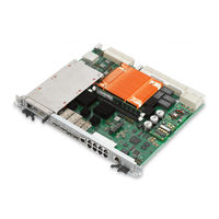
Emerson 6806800M67H Installation And Use Manual (140 pages)
Brand:
Emerson
| Category:
Network Hardware
| Size: 3.02 MB
Table of Contents
Table of Contents
7
Table 1-1 Standard Compliances
18
Mechanical Data
19
Table 1-3 Blade Variants - Ordering Information
20
Table 1-4 Blade Accessories - Ordering Information
20
Figure 1-1 Serial Number Location
22
Table 2-1 Environmental Requirements
26
Table 2-2 Power Requirements
28
Figure 3-1 ATCA-F140 Face Plate
49
Table
51
Table 3-2 Service Processor Ethernet RJ45 Connector Pin Assignment (J9)
51
Table 3-3 Service Processor Serial RS232 RJ45 Connector (J1)
51
Table
52
Table 3-4 QSFP+ Connector Pin Assignment
52
Table 3-5 SFP+ Connector Pin Assignment
53
Table 3-6 Master/Slave Sync Connector (J12-U1)
53
Table 3-7 Inter-Shelf Connectors (J12-L1, L2, L3, U2, U3)
54
Table 3-8 T1/E1 Port Connectors (J12-L4 and J12-U4)
54
Table 3-9 Zone 1 Connector P10 Pin Assignment
55
Table 3-10 Connector J20 Pin Assignment
56
Table 3-11 Connector J21 Pin Assignment
57
Table 3-12 Connector J22 Pin Assignment
57
Table 3-13 Connector J23 Pin Assignment
58
Table 3-14 Connector J24 Pin Assignment
58
Table 3-15 Connector J30 Pin Assignment
59
Table 3-16 Connector J31 Pin Assignment
59
Table 3-17 Connector J32 Pin Assignment
60
Figure 3-2 Module Connectors Locations
62
Table 3-18 AMC Bay Connector Pin Assignment
63
Table
65
Table 3-19 J2/J3 Memory Socket Pin Assignment
65
Table 3-20 J11 SAS/SATA Connector Pin Assignment
66
Table 3-21 P8 Eusb Header Pin Assignment
67
Table 3-22 P50 COP Header Pin Assignment
68
Table 3-23 P12 Asset JTAG Header Pin Assignment
68
Table 3-24 P9 H8S Console Header Pin Assignment
69
Table 3-25 Mechanical Switches
70
Figure 4-1 ATCA-F140 Block Diagram
71
Figure 4-2 IPMI Block Diagram
75
Table 4-1 Temperature Sensors
76
Figure 4-3 Boot Bank Selection Logic
79
Table 4-2 Boot Bank Write Protection
79
Table 4-3 Base Switch Mapping
81
Table 4-4 Fabric Switch Mapping (Default AXP1440 Chassis Configuration)
82
Table 4-5 Tested SFP+ Modules
85
Table 4-6 Tested QSFP+ Modules and Cables
86
Table
87
Figure 4-4 Base Channel Cross-Connect
88
Figure 4-5 Fabric Channel Cross-Connect
89
Figure 4-6 Telecom Clocking Subsystem
91
Figure 4-8 Reset Structure Diagram
94
Table 4-8 Reset Sources Versus Reset Outputs
95
Table
98
Table 5-1 Physical Address Map
107
Linux Devices
107
Table
108
Table 5-3 POST Result Format
108
Table 5-4 Post Results in SYS FW PROGRESS IPMI Sensor Reading Data
109
Table 5-5 SYS FW PROGRESS IPMI Sensor - POST Error Event Codes
110
POST Routines
110
Table 5-7 Environment Variable Post_Control
111
Table 5-8 ATCA-F140 Specific U-Boot Commands
112
Table 5-9 ATCA-F140 Specific U-Boot Environment Variables
112
Table B-1 Emerson Network Power - Embedded Computing Publications
119
Table B-2 Specifications
120
Related Products
Emerson 6888i
Emerson Rosemount 6888Xi
Emerson Rosemount 6888A
Emerson Rosemount 6888C
Emerson Rosemount 68Q Series
Emerson Rosemount 68 Series
Emerson Series 610
Emerson 6000RTL630
Emerson 6601
Emerson Fisher 67CFS
Emerson Categories
Controller
Control Unit
Transmitter
Measuring Instruments
Fan
More Emerson Manuals