beautypg.com
Manuals
Brands
Daikin Manuals
Heat Pump
EHSH08P50D
Daikin EHSH08P50D Manuals
Manuals and User Guides for Daikin EHSH08P50D. We have
3
Daikin EHSH08P50D manuals available for free PDF download: Installation And Maintenance Instructions Manual, Installation And Operating Manual
Daikin EHSH08P50D Installation And Maintenance Instructions Manual (588 pages)
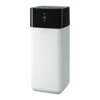
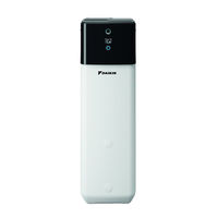
Integrated solar unit
Brand:
Daikin
| Category:
Boiler
| Size: 14.96 MB
Table of Contents
English
3
Table of Contents
3
Observing the Instructions
4
General Safety Precautions
4
Particular Safety Instructions
4
Meaning of Warnings and Symbols
5
Safety Instructions for Installation and Operation
5
General
5
Intended Use
6
Device Installation Room
6
Electrical Installation
6
Requirements for the Heating Water
6
Heating System and Sanitary Connection
7
Operation
7
Warranty Conditions
8
Instruct the Owner
8
Handover to Operator and Warranty
8
Product Description
9
Design and Components
9
Function of the 3-Way Switch Valves
12
Set-Up and Installation
13
Dimensions and Connection Dimensions
13
Transport and Delivery
15
Installing the Heat Pump
15
Selecting the Installation Site
15
Installing the Device
16
Moving the Controller Housing to the Service Position
17
Remove the Front Screen
17
Remove the Protective Cover
17
Preparing the Device for Installation
17
Open the Controller Housing
18
Removing the Bottom Thermal Insulation
18
Opening the Vent Valve
19
Aligning the Connections of the Heating Inflow and Return Flow
19
Making the Hood Opening
20
Installation of the External Heat Generator Connection Set
21
Installation of the DB Connection Kit
21
Installation of the Electric Backup Heater
21
Installing Optional Accessories
21
Installing the Rotary Switch of the Controller
21
Water Connection
22
Connecting Hydraulic Lines
22
Installation of the P Connection Kit
22
Connecting the Drain
23
Electrical Connection
24
Overall Connection Diagram
25
Position of the Printed Circuit Boards and Terminal Strips
26
Mains Connection
26
General Information on the Electrical Connection
26
Connecting the Heat Pump Outdoor Unit
26
Connecting an External Heat Generator
27
Connecting the Outside Temperature Sensor (Optional)
27
EBA (External Requirement Request)
27
External Switching Contact
27
Connecting the Room Thermostat
28
Connection of Optional Rocon System Components
29
Connecting the HP Convector
29
Connecting Switching Contacts (aux Outputs)
30
Off-Peak Mains Connection (HT/NT)
30
Connecting an Intelligent Controller (Smart Grid - SG)
31
Connection for Refrigerant
31
Laying Refrigerant Lines
31
Filling the Storage Tank
32
Filling the Heating System
32
Filling the System
32
Filling Hot Water Heat Exchangers
32
Checking the Water Quality and Adjusting the Pressure Gauge
32
Pressure Test and Filling the Refrigerant Circuit
32
Start-Up
33
Initial Commissioning
33
Requirements
33
Starting the Unit and Start-Up
33
Bleeding the Hydraulic System
33
Start-Up
34
Requirements
34
Re-Commissioning
34
Setting the Screed Program Parameter (Only as Required)
34
Checking the Minimum Flow
34
Hydraulic Connection
36
Hydraulic System Connection
36
Inspection and Maintenance
38
General Overview of Inspection and Maintenance
38
Inspection and Maintenance Tasks
39
Filling, Topping up the Storage Tank
39
Filling, Topping up the Heating System
40
Overview of Possible Malfunctions
42
Troubleshooting
42
Faults and Malfunctions
42
Fault Codes
45
Emergency Operation
55
Taking out of Operation
56
Temporary Shutdown
56
Draining the Storage Tank
56
Draining the Heating Circuit and Hot Water Circuit
57
Final Shutdown and Disposal
57
Technical Data
59
Basic Data
59
Characteristic Lines
60
Sensor Characteristic Lines
60
Minimum Floor Area and Ventilation Openings
61
Tightening Torque
61
Characteristic Curves for Pumps
61
Electrical Connection Diagram
63
List of Keywords
65
Deutsch
67
Allgemeine Sicherheitsvorkehrungen
68
Besondere Sicherheitsanweisungen
68
Anweisungen Beachten
69
Bedeutung der Warnhinweise und Symbole
69
Allgemein
70
Bestimmungsgemäße Verwendung
70
Geräteaufstellraum
70
Sicherheitsanweisungen für die Montage und den Betrieb
70
Anforderungen an das Heizungswasser
71
Betrieb
71
Elektrische Installation
71
Heizungsanlage und Sanitärseitiger Anschluss
71
Betreiber Einweisen
73
Garantiebestimmungen
73
Übergabe an Betreiber und Garantie
73
Produktbeschreibung
76
Funktion der 3-Wege-Umschaltventile
77
Abmessungen und Anschlussmaße
78
Aufstellung und Installation
78
Aufstellort Wählen
80
Transport und Anlieferung
80
Wärmepumpe Aufstellen
80
Gerät Aufstellen
81
Abdeckhaube Abnehmen
82
Frontscheibe Abnehmen
82
Gerät für Installation Vorbereiten
82
Regelungsgehäuse in Serviceposition Bringen
82
Regelungsgehäuse Öffnen
83
Wärmedämmung Abnehmen
83
Anschlüsse des Heizungsvor- und -Rücklaufs Ausrichten
84
Entlüftungsventil Öffnen
84
Haubenöffnung Herstellen
85
Drehtaster der Regelung Anbringen
86
Einbau Anschlussset Externer Wärmeerzeuger
86
Einbau DB-Anschlusskit
86
Einbau Elektrischen Backup-Heater
86
Optionales Zubehör Installieren
86
Einbau P-Anschlusskit
87
Hydraulische Leitungen Anschließen
87
Wasseranschluss
87
Ablauf Anschließen
88
Elektrischer Anschluss
89
Gesamtanschlussplan
90
Allgemeine Informationen zum Elektrischen Anschluss
91
Lage der Schaltplatinen und Klemmleisten
91
Netzanschluss
91
Wärmepumpenaußengerät Anschließen
91
Außentemperaturfühler (Optional) Anschließen
92
Externe Bedarfsanforderung (EBA)
92
Externer Schaltkontakt
92
Externen Wärmeerzeuger Anschließen
93
Raumthermostat Anschließen
93
Anschluss Optionaler Systemkomponenten
94
HP Convector Anschließen
94
Anschluss Schaltkontakte (AUX-Ausgänge)
95
Niedertarif-Netzanschluss (HT/NT)
95
Anschluss Intelligenter Regler (Smart Grid - SG)
96
Kältemittel Anschluss
96
Kältemittelleitungen Verlegen
96
Anlage Befüllen
97
Daikin Altherma EHS(X/H) Daikin Altherma Integrated Solar Unit
97
Druckprobe und Kältemittelkreis Befüllen
97
Heizungsanlage Befüllen
97
Speicherbehälter Befüllen
97
Warmwasserwärmeübertrager Befüllen
97
Wasserqualität Prüfen und Manometer Justieren
97
Erste Inbetriebnahme
98
Gerätestart und Inbetriebnahme
98
Hydraulik Entlüften
98
Inbetriebnahme
98
Voraussetzungen
98
Inbetriebnahme
99
Mindestdurchfluss Prüfen
99
Parameter Estrichprogramm Einstellen (nur bei Bedarf)
99
Voraussetzungen
99
Wiederinbetriebnahme
99
Hydraulische Anbindung
101
Hydraulische Systemanbindung
101
Allgemeines zu Inspektion und Wartung
103
Inspektion und Wartung
103
Inspektions- und Wartungsarbeiten
104
Speicherbehälter Befüllen, Nachfüllen
104
Heizungsanlage Befüllen, Nachfüllen
105
Fehler Erkennen und Störung Beheben
107
Fehler und Störungen
107
Übersicht über Mögliche Störungen
107
Fehlercodes
110
Notbetrieb
120
Außerbetriebnahme
121
Speicherbehälter Entleeren
121
Vorübergehende Stilllegung
121
Endgültige Stilllegung und Entsorgung
122
Heizkreis- und Warmwasserkreis Entleeren
122
Grunddaten
124
Technische Daten
124
Fühlerkennlinien
125
Kennlinien
125
Anzugsdrehmomente
126
Minimale Bodenfläche und Belüftungsöffnungen
126
Pumpenkennlinien
126
Elektrischer Anschlussplan
128
Stichwortverzeichnis
130
Français
131
Consignes de Sécurité Particulières
132
Consignes Générales de Sécurité
132
Respecter les Instructions
133
Signification des Avertissements et des Symboles
133
Généralités
134
Instructions Relatives à la Sécurité pour le Montage et le Fonctionnement
134
Local D'installation de L'appareil
134
Utilisation Conforme
134
Exigences en Matière D'eau de Chauffage
135
Fonctionnement
135
Installation de Chauffage et Raccordement Sanitaire
135
Installation Électrique
135
Dispositions de la Garantie
137
Instruction de L'exploitant
137
Remise à L'exploitant et Garantie
137
Description du Produit
138
Structure et Composants
138
Fonctionnement des Vannes D'inversion 3 Voies
141
Dimensions et Cotes de Raccordement
142
Mise en Place et Installation
142
Transport et Livraison
144
Choisir le Lieu de Montage
145
Mise en Place D'une Pompe à Chaleur
145
Montage de L'appareil
145
Enlever la Vitre Avant
146
Mise du Boîtier de Régulation en Position de Maintenance
146
Préparation de L'appareil pour L'installation
146
Retrait du Capot de Recouvrement
146
Ouverture du Boîtier de Régulation
147
Retrait de L'isolation Thermique
147
Orienter les Raccords du Départ et du Retour de Chauffage
148
Ouverture de la Soupape de Purge
148
Constitution D'une Ouverture du Capot
149
Installation D'accessoires en Option
150
Installation du Bouton Rotatif de la Régulation
150
Montage D'un Kit de Raccordement D'un Générateur de Chaleur Externe
150
Montage D'un Kit de Raccordement DB
150
Montage du Backup-Heater Électrique
150
Montage D'un Kit de Raccordement P
151
Raccordement en Eau
151
Raccordement des Conduites Hydrauliques
152
Connexion Électrique
153
Raccordement D'un Écoulement
153
Plan des Connexions Général
154
Généralités Concernant le Branchement Électrique
155
Position des Platines de Commande et des Borniers
155
Raccordement au Secteur
155
Raccordement de Pompe à Chaleur Externe
155
Branchement D'une Sonde de Température Extérieure (en Option)
156
Contact de Commutation Externe
156
Demande de Besoins Externe (DBE)
156
Branchement D'un Thermostat D'ambiance
157
Raccordement D'un Générateur de Chaleur Externe
157
Raccordement D'un Convecteur HP
158
Raccordement de Composants Système en Option
158
Connexion Bas Tarif au Réseau (TH/TB)
159
Raccordement de Contacts de Commutation (Sorties AUX)
159
Daikin Altherma EHS(X/H) Daikin Altherma Integrated Solar Unit
160
Pose de Conduites de Fluide Frigorigène
160
Raccordement D'une Régulation Intelligente (Smart Grid - SG)
160
Raccordement de Fluide Frigorigène
160
Contrôler la Qualité de L'eau et Ajuster le Manomètre
161
Faire un Test de Pression et Remplir le Circuit de Fluide Frigorigène
161
Remplissage de L'accumulateur
161
Remplissage de L'installation
161
Remplissage de L'installation de Chauffage
161
Remplissage L'échangeur de Chaleur ECS
161
Conditions Préalables
162
Démarrage de L'appareil et Mise en Service
162
Mise en Service
162
Première Mise en Service
162
Purge du Système Hydraulique
162
Conditions Préalables
163
Contrôle du Débit Minimum
163
Mise en Service
163
Réglage du Paramètre Programme de Chape (Uniquement si Nécessaire)
163
Wiederinbetriebnahme
163
Raccordement au Système Hydraulique
165
Raccordement Hydraulique
165
Généralités Sur L'inspection et la Maintenance
167
Inspection et Maintenance
167
Travaux D'inspection et de Maintenance
168
Remplissage, Appoint de L'installation de Chauffage
169
Remplissage, Appoint du Réservoir D'accumulateur
169
Aperçu des Dysfonctionnements Possibles
171
Défauts et Dysfonctionnements
171
Repérage des Défauts et Élimination des Dysfonctionnements
171
Codes D'erreur
174
Fonctionnement D'urgence
184
Mise Hors Service
186
Mise à L'arrêt Provisoire
186
Vidage de L'accumulateur
186
Vidange du Circuit de Chauffage et du Circuit D'eau Chaude
187
Mise Hors Service Définitive et Mise au Rebut
188
Données de Base
189
Données Techniques
189
Courbes Caractéristiques
190
Courbes Caractéristiques de la Sonde
190
Couples de Serrage
191
Courbes Caractéristiques de Pompe
191
Encombrement Minimal et Ouvertures Minimales de Ventilation
191
Plan des Bornes Électriques
193
Index des Mots Clés
196
Dutch
197
Algemene Veiligheidsmaatregelen
198
Bijzondere Veiligheidsinstructies
198
Betekenis Van de Waarschuwingen en Symbolen
199
Neem de Aanwijzingen in Acht
199
Algemeen
200
Opstellingsruimte Van Het Apparaat
200
Reglementair Gebruik
200
Veiligheidsinstructies Voor de Montage en de Werking
200
Eisen Aan Het Verwarmingswater
201
Elektrische Installatie
201
Verwarmingsinstallatie en Sanitairzijdige Aansluiting
201
Werking
201
Gebruiker Wegwijs Maken
202
Overdracht Aan Exploitant en Garantie
202
Opbouw en Onderdelen
203
Productbeschrijving
203
Functie Van de 3-Weg-Omschakelkleppen
206
Afmetingen en Aansluitmaten
207
Plaatsing en Installatie
207
Opstelplaats Kiezen
209
Transport en Bezorging
209
Warmtepomp Plaatsen
209
Apparaat Plaatsen
210
Afdekking Verwijderen
211
Apparaat Voor Installatie Voorbereiden
211
Regelingshuis Op Servicestand Zetten
211
Voorruit Afnemen
211
Regelingshuis Openen
212
Warmte-Isolatie Afnemen
212
Ontluchtingsklep Openen
213
Positioneren Van de Aansluitingen Van de Toevoer- en Retourleidingen Van de Verwarmingsinstallatie
213
Opening in de Afdekking Maken
214
Draaiknop Van de Regeling Aanbrengen
215
Inbouw Elektrische Backup-Heater
215
Montage Aansluitset Externe Warmteopwekker
215
Montage DB-Aansluitkit
215
Optioneel Toebehoren Installeren
215
Hydraulische Leidingen Aansluiten
216
Inbouw P-Aansluitkit
216
Wateraansluiting
216
Afvoer Aansluiten
217
Elektrische Aansluiting
218
Totaal Bedradingsschema
219
Algemene Informatie over de Elektrische Aansluiting
220
Netaansluiting
220
Positie Van de Schakelprintplaten en Klemrails
220
Warmtepomp Buitenapparaat Aansluiten
220
Buitentemperatuursensor (Optioneel) Aansluiten
221
Extern Schakelcontact
221
Extern Warmteverzoek (EBA)
221
Externe Warmteopwekker Aansluiten
222
Kamerthermostaat Aansluiten
222
Aansluiting Optionele Systeemcomponenten
223
HP Convector Aansluiten
223
Aansluiting Schakelcontacten (AUX-Uitgangen)
224
Laagtarief Netaansluiting (HT/NT)
224
Aansluiting Intelligente Regelaar (Smart Grid - SG)
225
Aansluiting Koudemiddel
225
Koudemiddelleidingen Leggen
225
Boiler Vullen
226
Daikin Altherma EHS(X/H) Daikin Altherma Integrated Solar Unit
226
Drukproef en Koudemiddelcircuit Vullen
226
Installatie Vullen
226
Verwarmingsinstallatie Vullen
226
Warmater Warmteoverbrenger Vullen
226
Waterkwaliteit Controleren en Manometer Afstellen
226
Eerste Inbedrijfstelling
227
Hydraulisch Systeem Ontluchten
227
Inbedrijfstelling
227
Start Van Het Apparaat en Inbedrijfstelling
227
Voorwaarden
227
Inbedrijfstelling
228
Minimum Debiet Controleren
228
Opnieuw in Bedrijf Stellen
228
Parameter Specievloerprogramma Instellen (Alleen Indien Nodig)
228
Voowaarden
228
Aansluiting Hydraulische Systeem
230
Hydraulische Aansluiting
230
Algemene Inspectie en Onderhoud
232
Inspectie en Onderhoud
232
Inspectie- en Onderhoudswerkzaamheden
233
Boiler Vullen, Bijvullen
234
Verwarmingssysteem Vullen, Bijvullen
234
Fouten en Storingen
236
Fouten Signaleren en Storingen Verhelpen
236
Overzicht Van Mogelijke Storingen
236
Foutcodes
239
Noodwerking
249
Aftappen Van Het Voorraadvat
250
Buitenbedrijfstelling
250
Tijdelijk Stilleggen
250
Definitieve Buitenbedrijfstelling en Afvoer
251
Leegmaken Van Het Verwarming- en Warmwatercircuit
251
Basisgegevens
253
Technische Gegevens
253
Karakteristieken
254
Sensorkarakteristieken
254
Draaimomenten
255
Minimum Vloeroppervlak en Ventilatieopeningen
255
Pompkarakteristieken
255
Elektrisch Aansluitschema
257
Trefwoordenlijst
259
Installatie- en Onderhoudshandleiding
260
Daikin EHSH08P50D Installation And Operating Manual (344 pages)
Brand:
Daikin
| Category:
Heat Pump
| Size: 14.07 MB
Table of Contents
Table of Contents
2
General Safety Precautions
3
Particular Safety Instructions
3
Observing the Instructions
3
Meaning of Warnings and Symbols
4
Safety Instructions for Installation and Operation
4
General
4
Intended Use
5
Installation Room
5
Electrical Installation
6
Requirements for Heating and Storage Water
6
Heating System and Sanitary Connection
6
Operation
6
Maintenance, Troubleshooting and Decommissioning
6
Warranty Conditions
7
Product Description
8
Design and Components
8
Function of the 3-Way Changeover Valves
10
Set-Up and Installation
11
Dimensions and Connection Dimensions
11
Transport and Delivery
12
Installing the Heat Pump
12
Selecting the Installation Site
12
Installing the Device
13
Preparing the Device for Installation
13
Remove the Front Screen
13
Remove the Protective Cover
14
Moving the Switch Box to the Service Position
14
Open the Switch Box
14
Removing the Bottom Thermal Insulation
15
Opening the Air Purge Valve
15
Aligning the Connections of the Heating Inflow and Return Flow
16
Making the Hood Opening
17
Installing the Rotary Switch of the Controller
17
Securing the Hood
17
Installing Optional Accessories
18
Installation of Electric Backup Heater (Ekbuxx)
18
Installation of the External Heat Generator Connection Set (EKBUHSWB)
18
Installation of the DB Connection Kit
18
Installation of the P Connection Kit
18
Water Connection
19
Minimum Water Volume
19
Connecting Hydraulic Lines
19
Connecting the Drain
20
Electrical Connection
20
Overall Connection Diagram
22
Position of the Pcbs and Terminal Strips
23
Mains Connection
23
General Information on the Electrical Connection
23
Connecting the Heat Pump Outdoor Unit
23
Connecting the Outdoor Temperature Sensor (Optional)
24
External Switching Contact
24
EBA (External Requirement Request)
24
Connecting an External Heat Generator
25
Connecting the Room Thermostat
26
Connection of Optional Rocon System Components
26
Connecting the HP Convector
26
Connecting Switching Contacts (AUX Outputs)
27
Low Rate Mains Connection (HT/NT)
27
Connecting an Intelligent Controller (Smart Grid - SG)
28
Connection for Refrigerant
28
Laying Refrigerant Piping
28
Pressure Test and Filling the Refrigerant Circuit
28
Filling the System
29
Checking the Water Quality and Adjusting the Manometer
29
Filling Hot Water Heat Exchangers
29
Filling the Storage Tank
29
Filling the Heating System
29
Configuration
30
Check List for Start-Up
31
Requirements
31
Commissioning at Low Ambient Temperatures
31
Bleeding the Hydraulic System
31
Checking the Minimum Flow
32
Start Screed Drying (Only if Required)
32
Commissioning Checklist
32
Handover to the Operating Company
33
Technical Data
33
Information on the Type Plate
33
Characteristic Lines
33
Sensor Characteristic Lines
33
Characteristic Curves for Pumps
34
Tightening Torques
34
Minimum Floor Area and Ventilation Openings
34
Electrical Connection Diagram
36
Piping Diagram for Refrigerant Circuit
38
Allgemeine Sicherheitsvorkehrungen
40
Besondere Sicherheitsanweisungen
40
Anweisungen Beachten
41
Bedeutung der Warnhinweise und Symbole
41
Sicherheitsanweisungen für die Montage und den Betrieb
41
Allgemein
41
Bestimmungsgemäße Verwendung
42
Geräteaufstellraum
42
Elektrische Installation
43
Anforderungen an das Heizungs- und Speicherwasser
43
Heizungsanlage und Sanitärseitiger Anschluss
44
Betrieb
44
Wartung, Fehlerbehebung und Außerbetriebnahme
44
Garantiebestimmungen
44
Produktbeschreibung
45
Aufbau und Bestandteile
45
Funktion der 3-Wege-Umschaltventile
47
Aufstellung und Installation
48
Abmessungen und Anschlussmaße
48
Transport und Anlieferung
49
Wärmepumpe Aufstellen
49
Aufstellort Wählen
49
Gerät Aufstellen
50
Gerät für Installation Vorbereiten
51
Frontscheibe Abnehmen
51
Abdeckhaube Abnehmen
51
Regelungsgehäuse in Serviceposition Bringen
51
Regelungsgehäuse Öffnen
52
Wärmedämmung Abnehmen
52
Entlüftungsventil Öffnen
53
Anschlüsse des Heizungsvor- und -Rücklaufs Ausrichten
53
Haubenöffnung Herstellen
54
Drehtaster der Regelung Anbringen
55
Haube Sichern
55
Optionales Zubehör Installieren
55
Einbau Elektrischer Backup-Heater (Ekbuxx)
55
Einbau Anschlussset Externer Wärmeerzeuger (EKBUHSWB)
55
Einbau DB-Anschlusskit
56
Einbau P-Anschlusskit
56
Wasseranschluss
56
Mindestwasservolumen
57
Hydraulische Leitungen Anschließen
57
Ablauf Anschließen
58
Elektrischer Anschluss
58
Gesamtanschlussplan
60
Lage der Schaltplatinen und Klemmleisten
61
Netzanschluss
61
Allgemeine Informationen zum Elektrischen Anschluss
61
Wärmepumpenaußengerät Anschließen
61
Außentemperaturfühler (Optional) Anschließen
62
Externer Schaltkontakt
62
Externe Bedarfsanforderung (EBA)
62
Externen Wärmeerzeuger Anschließen
63
Raumthermostat Anschließen
63
Anschluss Optionaler Systemkomponenten
64
HP Convector Anschließen
64
Anschluss Schaltkontakte (AUX-Ausgänge)
65
Niedertarif-Netzanschluss (HT/NT)
65
Anschluss Intelligenter Regler (Smart Grid - SG)
66
Kältemittel Anschluss
66
Kältemittelleitungen Verlegen
66
Druckprobe und Kältemittelkreis Befüllen
66
Anlage Befüllen
67
Wasserqualität Prüfen und Manometer Justieren
67
Warmwasserwärmeübertrager Befüllen
67
Speicherbehälter Befüllen
67
Heizungsanlage Befüllen
68
Konfiguration
68
Inbetriebnahme
69
Voraussetzungen
69
Inbetriebnahme bei Niedrigen Umgebungstemperaturen
69
Hydraulik Entlüften
69
Mindestdurchfluss Prüfen
70
Estrichtrocknung Starten (nur bei Bedarf)
70
Inbetriebnahme-Checkliste
70
Übergabe an den Betreiber
71
Technische Daten
71
Angaben auf dem Typenschild
71
Kennlinien
71
Fühlerkennlinien
71
Pumpenkennlinien
72
Anzugsdrehmomente
72
Minimale Bodenfläche und Belüftungsöffnungen
72
Elektrischer Anschlussplan
74
Rohrleitungsplan Kältemittelkreis
76
Consignes de Sécurité Générales
78
Consignes de Sécurité Spéciales
78
Respecter Les Instructions
79
Signification des Avertissements Et des Symboles
79
Instructions Relatives À la Sécurité Pour Le Montage Et Le Fonctionnement
80
Généralités
80
Utilisation Conforme
80
Local D'installation de L'appareil
81
Installation Électrique
81
Exigences en Matière D'eau de Chauffage Et ECS
81
Équipement de Chauffage Et Raccordement Sanitaire
82
Exploitation
82
Maintenance, Dépannage Et Mise Hors Service
82
Dispositions de la Garantie
82
Description du Produit
83
Structure Et Composants
83
Fonctionnement des Vannes D'inversion 3 Voies
85
Mise en Place Et Installation
86
Dimensions Et Cotes de Raccordement
86
Transport Et Livraison
87
Mise en Place D'une Pompe À Chaleur
88
Choix du Lieu D'installation
88
Installation de L'appareil
88
Préparation de L'appareil À L'installation
89
Retrait de la Vitre Avant
89
Retirer Le Capot
89
Mise du Boîtier de Régulation en Position de Maintenance
90
Ouverture du Boîtier de Régulation
90
Retrait de L'isolation Thermique
90
Ouverture de la Vanne de Purge D'air
91
Orientation des Raccords de Départ Et de Retour de Chauffage
91
Constitution D'une Ouverture du Capot
93
Installation du Bouton Rotatif de la Régulation
93
Bloquer Le Capot
93
Installer Les Accessoires en Option
93
Montage du Backup-Heater Électrique (Ekbuxx)
93
Montage D'un Kit de Raccordement D'un Générateur de Chaleur Externe (EKBUHSWB)
93
Montage D'un Kit de Raccordement DB
94
Montage D'un Kit de Raccordement P
94
Raccordement en Eau
95
Volume D'eau Minimum
95
Raccordement des Conduites Hydrauliques
95
Raccordement D'un Écoulement
96
Raccordement Électrique
97
Plan des Connexions Général
98
Position des Platines de Commande Et des Borniers
99
Raccordement Au Réseau
99
Généralités Concernant Le Branchement Électrique
99
Raccordement de Pompe À Chaleur Externe
99
Branchement D'un Capteur de Température Extérieure (en Option)
100
Contact de Commutation Externe
100
Demande de Besoins Externe (DBE)
100
Raccordement D'un Générateur de Chaleur Externe
101
Branchement D'un Thermostat D'ambiance
102
Raccordement de Composants Système en Option
102
Raccordement D'un Convecteur HP
102
Raccordement de Contacts de Commutation (Sorties AUX)
103
Connexion Bas Tarif Au Réseau (TH/TB)
103
Raccordement D'une Régulation Intelligente (Smart Grid - SG)
104
Raccordement de Réfrigérant
104
Pose de Conduites de Réfrigérant
104
Faire un Test de Pression Et Remplir Le Circuit de Réfrigérant
104
Remplissage de L'installation
105
Contrôler la Qualité de L'eau Et Ajuster Le Manomètre
105
Remplissage L'échangeur de Chaleur ECS
105
Remplissage de L'accumulateur
105
Remplissage de L'installation de Chauffage
106
Configuration
106
Mise en Service
107
Conditions
107
Mise en Service À Basses Températures Ambiantes
107
Purge du Système Hydraulique
107
Contrôle du Débit Minimum
108
Démarrer la Fonction de Séchage de Chape (Uniquement si Nécessaire)
108
Liste de Contrôle de Mise en Service
109
Remise À L'exploitant
109
Caractéristiques Techniques
110
Indications Sur la Plaque Signalétique
110
Courbes Caractéristiques
110
Courbes Caractéristiques de Capteur
110
Courbes Caractéristiques de la Pompe
111
Couples de Serrage
111
Encombrement Minimal Et Ouvertures Minimales de Ventilation
111
Plan des Bornes Électriques
113
Plan des Conduites du Circuit de Réfrigérant
115
Algemene Veiligheidsmaatregelen
117
Bijzondere Veiligheidsinstructies
117
Neem de Aanwijzingen in Acht
118
Betekenis Van de Waarschuwingen en Symbolen
118
Veiligheidsinstructies Voor de Montage en de Werking
119
Algemeen
119
Reglementair Gebruik
119
Plaatsingsruimte Voor Het Apparaat
120
Elektrische Installatie
120
Vereisten Voor Het Verwarmings- en Opslagwater
120
Verwarmingssysteem en Aansluiting Op Sanitair
121
Werking
121
Onderhoud, Probleemoplossing en Buitenbedrijfstelling
121
Garantiebepalingen
121
Productbeschrijving
122
Opbouw en Onderdelen
122
Werking Van de 3-Weg Omschakelkleppen
124
Plaatsing en Installatie
125
Afmetingen en Aansluitmaten
125
Transport en Levering
126
Warmtepomp Plaatsen
126
Installatieplaats Kiezen
126
Apparaat Plaatsen
127
Apparaat Voorbereiden Voor Installatie
128
Frontpaneel Verwijderen
128
Afdekking Verwijderen
128
Regelingsbehuizing Op Servicestand Zetten
128
Regelingsbehuizing Openen
129
Warmte-Isolatie Verwijderen
129
Ontluchtingsklep Openen
130
Aansluitingen Van de Verwarmingsaanvoer en -Retour Uitlijnen
130
Opening in de Afdekking Maken
131
Draaiknop Van de Regeling Aanbrengen
132
Kap Borgen
132
Optioneel Toebehoren Installeren
132
Installatie Van Een Elektrische Back-Upheater (Ekbuxx)
132
Installatie Aansluitset Voor Externe Warmtebron (EKBUHSWB)
132
Montage DB-Aansluitkit
132
Inbouw P-Aansluitkit
133
Wateraansluiting
133
Minimaal Watervolume
134
Hydraulische Leidingen Aansluiten
134
Afvoer Aansluiten
135
Elektrische Aansluiting
135
Algemeen Aansluitschema
136
Positie Van de Schakelprintplaten en Klemrails
137
Aansluiting Op Het Net
137
Algemene Informatie over de Elektrische Aansluiting
137
Warmtepomp-Buitenunit Aansluiten
137
Buitentemperatuursensor (Optioneel) Aansluiten
138
Extern Schakelcontact
138
Externe Warmtevraag (EBA)
138
Externe Warmtebron Aansluiten
139
Kamerthermostaat Aansluiten
139
Aansluiting Van Optionele Systeemcomponenten
140
HP Convector Aansluiten
140
Aansluiting Schakelcontacten (AUX-Uitgangen)
141
Laagtarief Netaansluiting (HT/NT)
141
Aansluiting Intelligente Regelaar (Smart Grid - SG)
142
Aansluiting Koudemiddel
142
Koudemiddelleidingen Leggen
142
Drukproef en Koudemiddelcircuit Vullen
142
Systeem Vullen
143
Waterkwaliteit Controleren en Manometer Afstellen
143
Warmwater-Warmtewisselaar Vullen
143
Boiler Vullen
143
Verwarmingssysteem Vullen
144
Configuratie
144
Inbedrijfstelling
145
Voorwaarden
145
Inbedrijfstelling Bij Lage Omgevingstemperaturen
145
Hydraulisch Systeem Ontluchten
145
Minimum Debiet Controleren
146
Drogen Van de Dekvloer Starten (Alleen Indien Nodig)
146
Checklijst Voor Inbedrijfstelling
146
Overdracht Aan de Exploitant
147
Technische Gegevens
147
Gegevens Op Het Typeplaatje
147
Karakteristieke Curven
147
Sensorkarakteristieken
147
Pompkarakteristieken
148
Aandraaimomenten
148
Minimale Vloeroppervlakte en Ventilatieopeningen
148
Elektrisch Schakelschema
151
Leidingendiagram Koudemiddelcircuit
153
Precauciones Generales de Seguridad
155
Indicaciones Especiales de Seguridad
155
Seguir las Instrucciones
156
Significado de Los Símbolos y Advertencias
156
Indicaciones de Seguridad para el Montaje y el Funcionamiento
157
Generalidades
157
Uso Previsto
157
Lugar de Emplazamiento del Equipo
158
Instalación Eléctrica
158
Exigencias para el Agua de Calefacción y del Acumulador
158
Sistema de Calefacción y Conexión del Lado Sanitario
159
Funcionamiento
159
Mantenimiento, Subsanación de Errores y Puesta Fuera de Servicio
159
Garantía
159
Descripción del Producto
160
Estructura y Componentes
160
Funcionamiento de la Válvula de Conmutación de 3 Vías
162
Colocación E Instalación
163
Dimensiones y Medidas de Conexión
163
Transporte y Entrega
164
Emplazamiento de la Bomba de Calor
165
Seleccionar el Lugar de Emplazamiento
165
Emplazamiento del Aparato
165
Preparar el Equipo para la Instalación
166
Retirar el Panel Frontal
166
Retirar la Cubierta
166
Situar la Carcasa de la Regulación en la Posición de Servicio
167
Abrir la Carcasa de la Regulación
167
Retirar el Aislamiento Térmico
167
Abrir la Válvula de Purga
168
Orientar las Conexiones de Impulsión y Retorno de Calefacción
168
Crear la Abertura en la Cubierta
169
Colocar el Selector de Regulación
170
Asegurar la Cubierta
170
Instalar Los Accesorios Opcionales
170
Montaje del Calentador de Reserva Eléctrico (Ekbuxx)
170
Montaje del Conjunto de Conexiones del Generador Térmico Externo (EKBUHSWB)
170
Montaje del Kit de Conexión DB
171
Montaje del Kit de Conexión P
171
Conexión de Agua
171
Volumen Mínimo de Agua
172
Conectar las Tuberías Hidráulicas
172
Conectar el Desagüe
173
Conexión Eléctrica
173
Esquema General de Conexiones
175
Posición de las Pletinas de Conexión y Regletas de Bornes
176
Conexión a la Red
176
Información General sobre la Conexión Eléctrica
176
Conectar la Unidad Exterior de Bomba de Calor
176
Conectar el Sensor de Temperatura Exterior (Opcional)
177
Contacto de Conmutación Externo
177
Demanda Necesaria Externa (EBA)
177
Conectar el Generador Térmico Externo
178
Conectar el Termostato para Interiores
179
Conexión de Componentes de Sistema Opcionales
179
Conectar el Convector HP
179
Conexión de Los Contactos de Conmutación (Salidas AUX)
180
Conexión de Red de Tarifa Reducida (HT/NT)
180
Conexión del Regulador Inteligente (Smart Grid - SG)
181
Conexión de Agente Refrigerante
181
Tendido de Los Conductos de Agente Refrigerante
181
Llene la Prueba de Presión y el Circuito de Refrigerante
181
Llenar la Instalación
182
Comprobar la Calidad del Agua y Ajustar el Manómetro
182
Llenar el Intercambiador de Calor de Agua Caliente
182
Llenado del Depósito Acumulador
182
Llenar el Sistema de Calefacción
183
Daikin EHSH08P50D Installation And Maintenance Instructions Manual (68 pages)
Brand:
Daikin
| Category:
Heat Pump
| Size: 17.97 MB
Table of Contents
Installation and Maintenance
1
Table of Contents
3
1 General Safety Precautions
4
Particular Safety Instructions
4
Observing the Instructions
4
Meaning of Warnings and Symbols
5
Safety Instructions for Installation and Operation
5
General
5
Intended Use
6
Device Installation Room
6
Electrical Installation
6
Requirements for the Heating Water
6
Heating System and Sanitary Connection
7
Operation
7
2 Handover to Operator and Warranty
8
Instruct the Owner
8
Warranty Conditions
8
3 Product Description
9
Design and Components
9
Function of the 3-Way Switch Valves
11
4 Set-Up and Installation
12
Dimensions and Connection Dimensions
12
Transport and Delivery
13
Installing the Heat Pump
13
Selecting the Installation Site
13
Installing the Device
14
Preparing the Device for Installation
15
Remove the Front Screen
15
Remove the Protective Cover
15
Moving the Controller Housing to the Service Position
15
Open the Controller Housing
16
Removing the Bottom Thermal Insulation
16
Opening the Vent Valve
17
Aligning the Connections of the Heating Inflow and Return Flow
17
Making the Hood Opening
18
Installing the Rotary Switch of the Controller
18
Installing Optional Accessories
18
Installation of the Electric Backup Heater
18
Installation of the External Heat Generator Connection Set
18
Installation of the DB Connection Kit
19
Installation of the P Connection Kit
19
Water Connection
19
Connecting Hydraulic Lines
20
Connecting the Drain
21
Electrical Connection
21
Overall Connection Diagram
22
Position of the Printed Circuit Boards and Terminal Strips
23
Mains Connection
23
General Information on the Electrical Connection
23
Connecting the Heat Pump Outdoor Unit
23
Connecting the Outside Temperature Sensor (Optional)
24
External Switching Contact
24
EBA (External Requirement Request)
24
Connecting an External Heat Generator
24
Connecting the Room Thermostat
25
Connection of Optional Rocon System Components
26
Connecting the HP Convector
26
Connecting Switching Contacts (AUX Outputs)
27
Off-Peak Mains Connection (HT/NT)
27
Connecting an Intelligent Controller (Smart Grid - SG)
28
Connection for Refrigerant
28
Laying Refrigerant Lines
28
Pressure Test and Filling the Refrigerant Circuit
29
Filling the System
29
Checking the Water Quality and Adjusting the Pressure Gauge
29
Filling Hot Water Heat Exchangers
29
Filling the Storage Tank
29
Filling the Heating System
29
Related Products
Daikin EHSH04P30A
Daikin EHSH08P30A
Daikin EHSH08P50A
Daikin EHSH04P30D
Daikin EHSH08P30D
Daikin EHSH04P30D2
Daikin EHSH08P30D2
Daikin EHSHB04P30D
Daikin EHSHB08P30D
Daikin EHSHB04P30D2
Daikin Categories
Air Conditioner
Heat Pump
Remote Control
Chiller
Fan
More Daikin Manuals