beautypg.com
Manuals
Brands
ABB Manuals
DC Drives
ACS580MV
ABB ACS580MV Manuals
Manuals and User Guides for ABB ACS580MV. We have
6
ABB ACS580MV manuals available for free PDF download: Commissioning Manual, Hardware Manual, Quick Manual
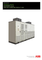
ABB ACS580MV Hardware Manual (146 pages)
200 kW to 6300 kW, 6 kV to 11 kV
Brand:
ABB
| Category:
DC Drives
| Size: 26.93 MB
Table of Contents
Table of Contents
5
Terms
11
Trademarks
12
1 Safety Instructions
13
Contents of this Chapter
13
User's Responsibilities
14
General Safety Information
14
Possible Residual Risks
15
Safety Labels
16
General Safety in Installation, Start-Up and Maintenance
16
Electrical Safety in Installation, Start-Up and Maintenance
17
Precautions before Electrical Work
17
Additional Instructions and Notes
18
Grounding
18
2 Introduction to the Manual
19
Contents of this Chapter
19
Equipment Covered by the Manual
19
Target Groups and Required Qualifications
20
Handling
20
Mechanical Installation
20
Electrical Installation
20
Operation
20
Maintenance
21
Contents of the Manual
21
Relevant Chapters of the Manual
21
Related Manuals
21
User's Responsibilities
21
Intended Equipment Use
22
Cyber Security Disclaimer
22
Categorization by Frame Size and Option Code
22
3 Function and Hardware Description
23
Contents of this Chapter
23
Product Overview
23
Rating Plate
24
System Overview
26
Power Supply Configuration
26
Main Power Supply to Input Isolation Transformer
26
Auxiliary Power Supply
27
Standard Configuration
27
Alternative Configurations
27
Cabinet Layouts
27
Terminal Unit
28
Transformer Unit
29
Inverter Unit
29
Power Module
30
Charging Circuit
32
Discharging the Power Modules
32
Control Unit
33
Cabinet Design
35
Protection Class
35
Door Locking System
35
Cooling System
37
Function
37
Fan Groups
37
Starting, Stopping
37
Air Flow Inside the Drive
37
Temperature Monitoring
38
4 Control System and Interfaces
39
Contents of this Chapter
39
Main Components
39
Control Block Diagram
40
Control Unit (BCU)
41
I/O Extension and Fieldbus Modules
41
Control Tasks
42
Parameters and Application Macros
42
Control Locations and Operating Modes
43
Application Macros
43
Local Operating Elements
43
Local Control Panel
43
Supply OFF/ON Pushbuttons
44
Alarm and Fault Indications
45
Emergency off
45
Monitoring
45
I/O Interfaces
45
Customer Control and Process I/Os
45
I/O Signal Requirements
49
Communication Interfaces
49
5 Guidelines for Planning the Electrical Installation
51
References
51
Limitation of Liability
51
6 Transportation, Storage and Disposal
53
Contents of this Chapter
53
Safety
53
Transport Conditions
53
Unpacking and Inspection
54
Lifting and Transportation
54
General Notes on Transportation
54
Dimensions and Weights
54
Using a Crane
55
Using a Forklift
56
Storage
57
Storage Conditions
57
Preparing Cabinets for Storage
57
Storage and Handling Instructions for Spare Parts
57
Reforming Capacitors of the Power Modules
58
Disposal of Packaging Materials and Components
58
7 Mechanical Installation
59
Contents of this Chapter
59
Safety
59
Examining the Installation Site
59
Necessary Tools
60
Overview on Installation Work
60
General Notes on Installation
60
Dimensions, Clearances
60
Preparing the Foundation
60
Cable Ducts
60
Fire Protection
60
Cabinet Roof
61
Installing Fan Units
61
Installation
61
Bolting Together the Units
62
Fixing Units to the Floor
62
Location of Tool Kit and Accessories
63
8 Electrical Installation
65
Contents of this Chapter
65
Safety
65
Overview of Installation Work
65
Cable Requirements
66
Parallel Routing of Power Cables
66
Terminal Sizes for Auxiliary and Control Connections
66
Ground Cable and Cable Shield Connections
67
Grounding of the Drive System
67
Cables and PE Busbar between Integrated Transformer and Drive
69
Cable Entries for External Connections
71
Power Cable Entry Via Holes in Cable Entry Plate
71
Control and Auxiliary Cable Entry with EMC Plates
71
Installing Power and Ground Cables
73
Further Information
73
Preparing the Cable Entry and the Cables
73
Determining the Cable Length
73
Preparing Cables for Entry Plates
73
Connecting the Cables
75
Connections
78
Bolted Connections
78
Installing Auxiliary, Control and Serial Communication Cables
79
Further Information
79
Preparing the Cable Entry and the Cables
80
Determining the Cable Length
80
Routing the Cables
80
Preparing the Cables
81
Connecting the Cables
82
Control and Power Supply Cables for Fan Units
83
Sealing Holes in Entry Plates
83
Final Checks
84
9 Installation Checklist
85
Contents of this Chapter
85
Checklist
86
10 Operation
91
Contents of this Chapter
91
Operating Conditions
91
Safety
91
Overview
91
Overview on Drive Status and Sequences
92
Status Indications
92
Start Sequence of the Drive
93
Stop Sequence of the Drive
94
Emergency Stop Sequence
95
Energizing and Starting the Drive
95
Checks before Starting the Drive
95
Starting the Drive from Remote
96
Starting the Drive Locally
96
Stopping the Drive
97
11 Fault Tracing
99
Contents of this Chapter
99
Alarm and Fault Indications
99
Warning and Fault Messages
100
Diagnosis Data and Parameter Backup
100
12 Maintenance
101
Contents of this Chapter
101
Preparation for Maintenance Work
102
Documentation and Reporting of Maintenance Work
102
Required Tools and Equipment
102
Storage and Handling of Spare Parts
102
Shutting down the Drive for Maintenance
102
De-Energizing the Drive
103
Unlocking and Locking the Doors
104
Connecting a Grounding Set
104
Grounding Power Module with Grounding Hook
107
Required Tools
107
Procedure
108
Starting the Drive after Maintenance
108
Emergency Release of the Door Safety Switch
108
Safety-Switch Settings
109
Unlocking
110
Safety-Switch Setting 2
110
Cleaning the Interior of the Cabinet
111
Replacing the Door Air Filters
111
Cleaning Heat Sinks of Power Modules
112
Replacing Roof AC Fans
113
Required Tools and Equipment
115
Replacing Roof EC Fans
116
Procedure
116
Replacing the Power Modules
118
Required Manpower and Tools
118
Replacement of a Power Module Frame Size R1 - R3
118
Dismounting
119
Mounting
120
Converter Module Testing and Repair
120
Replacing the Power Module Fuse R1 - R3
120
Replacement of a Power Module Frame Size R4 - R6
121
Dismounting
121
Mounting
123
Converter Module Testing and Repair
123
Replacing the Power Module Fuse R4 - R6
123
Replacement of a Power Module Frame Size R7 - R9
124
Dismounting
124
Mounting
129
Replacing the Power Module Fuse R7 - R9
131
Capacitors
131
Reforming Capacitors of the Power Modules
132
Testing Main Power Supply Circuit
132
Replacing the Control Panel Battery
132
Circuit Board Replacements
132
Control Unit (BCU) and Memory Unit (ZMU)
132
Replacing the SD Memory Card
135
Replacing the Real-Time Clock Battery
135
High Voltage Divider Board
136
CVMI2 Board
136
Control Hub
136
Control Hub Daughter Board
137
Maintenance Schedule
139
Drive Seasonal Operation
140
Shutting down the Drive for Maintenance
140
Maintain the Drive for Preservation
140
Maintain the Drive before Restarting up
140
Start the Drive Following Chapter of "Operation
141
13 Technical Data
143
Product and Service Inquiries
145
Product Training
145
Document Library on the Internet
145
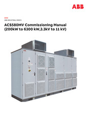
ABB ACS580MV Commissioning Manual (150 pages)
200kW to 6300 kW,3.3kV to 11 kV
Brand:
ABB
| Category:
DC Drives
| Size: 19.15 MB
Table of Contents
Table of Contents
5
Terms
9
Trademarks
10
1 Safety Instructions
11
Contents of this Chapter
11
2 Introduction to the Manual
13
Contents of this Chapter
13
Scope of Commissioning
13
Requirement for Reports
13
MV Drives Supportline Contact
14
3 Standard Commissioning Process
15
Pre-Commissioning Check Lists
15
Contents of this Chapter
15
Office Preparation Check List
15
Required Tools
16
Scope of Delivery
18
Checking the Pre-Conditions for Commissioning
18
Inspection of Installation
22
Converter Room
23
Converter
23
Motor
23
Commissioning Third-Party Equipments
24
Main Circuit Breaker (MCB)
24
Power Cables
24
Protection Relays
27
Motor
28
Insulation Resistance Measurements
28
Preparations
28
External MCB Insulation Test
28
Converter Insulaiton Test
29
Motor Insulation Test
30
Power Cables Insulation Test
31
Preparing the Converter for Start-Up
32
Connecting the Auxiliary Supply
32
Check Terminal X1 Terminal before Energizing Auxiliary Supply
32
Other Checking Items
34
Loading Software and Prepare Drivestartup
36
Loading Software to All the Control Boards
36
Commissioning Software Tools on PC
59
Cold Commissioning by Drivestartup
64
Create the New Project
64
Connected Equipment Inspection
67
Cold Commissioning
68
Hot Commissioning by Drivestartup
75
Close MCB and Load Power Module Software
75
Cooling and Heating System Testing
75
Motor First Run
77
Fly Start
78
Control from Overriding System
80
Motor Ramp up and down with Load
81
Vector Control
82
Grid Loss Ride through Test
84
Finalizing the Commissioning
84
Parameters Backup
84
SD Card Data Backup
85
Spare Parts Software Version
85
Customer Training
85
Customer Approval
86
Create the Commissioning Report
86
Prepare the Field Service Report by Drivestartup
87
Customer Documentation
94
Documentation and Backup Copies to MV Drives Supportline
94
Duration and Description of Commissioning
94
Duration and Description of Typical Commissioning
95
4 Option
97
MBU Commissioning
97
Insulation Test
100
Commissioning for MBU=0001 Option
100
Commissioning for MBU=0002 or MBU=0003 Option
102
SBU Commissioning
105
Safety
105
Software Requirements
105
Inspection of Installation
105
Insulation Test
106
Download Software
106
SBU Phase Order Check Procedure
108
SBU Cold Commissioning
111
SBU Hot Commissioning
124
Master/Follower Functionality
129
Contents of this Chapter
129
General
129
General Parameter Setting
131
Remote Connectivity
136
Contents of this Chapter
136
Make the Drive Ready
136
NETA-21 Setup
137
Finalizing the Connection
139
5 Preventive Maintenance
141
Contents of this Chapter
141
Maintenance Schedule
141
Regular Inspection
142
Preventive Replacement Schedule
142
Insulation Resistance Measurement
143
Converter Insulation Resistance
143
Transformer Insulation Resistance
143
Motor Insulation Resistance
144
Optical Fibers
144
Visual Check
144
Attenuation Measurement
144
Communication Test
145
Bypass Unit
146
Isolation Switches for Manual Bypass
146
Contactor for Auto Bypass
146
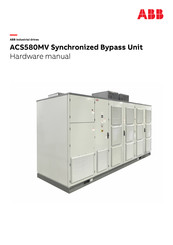
ABB ACS580MV Hardware Manual (62 pages)
Synchronized Bypass Unit
Brand:
ABB
| Category:
Industrial Electrical
| Size: 4.63 MB
Table of Contents
Table of Contents
5
Terms
9
Trademarks
10
1 Safety Instructions
11
Contents of this Chapter
11
User's Responsibilities
12
General Safety Information
12
Possible Residual Risks
13
Safety Labels
14
General Safety in Installation, Start-Up and Maintenance
14
Electrical Safety in Installation, Start-Up and Maintenance
15
Precautions before Electrical Work
15
Additional Instructions and Notes
16
Grounding
16
2 Introduction to the Manual
17
Contents of this Chapter
17
Applicable Products
17
Contact Information
17
Equipment Covered by the Manual
18
Target Groups and Required Qualifications
18
Related Manuals
18
User's Responsibilities
18
Intended Equipment Use
18
Cyber Security Disclaimer
18
Categorization by Frame Size and Option Code
18
3 Function and Hardware Description
19
Contents of this Chapter
19
Function Introduction
19
SBU Function Description
19
Transfer Sequence
20
Options
21
Product Overview
21
Output Choke
22
Space Heater
22
RSYC- 01 Unit
22
Overall View of the Unit
22
Operation
22
Hmi
22
MAU (Marshalling Unit) Layout
25
Doorlock
26
Cooling System
26
Function
26
Air Flow Inside MAU and SBU
27
4 Control System and Interfaces
29
Contents of this Chapter
29
Main Components
29
Control Block Diagram
30
I/O Interfaces
31
Customer Control and Process I/Os
31
I/O Signal Requirements
32
Communication Interfaces
32
5 Transportation
33
Contents of this Chapter
33
Safety
33
Lifting and Transportation
33
Dimensions and Weights
33
6 Mechanical Installation
35
Contents of this Chapter
35
Safety
35
Installing Air Outlet
35
Installation
36
7 Electrical Installation
37
Contents of this Chapter
37
Safety
37
Overview of Installation Work
37
Cable Requirements
38
Parallel Routing of Power Cables
38
Terminal Sizes for Auxiliary and Control Connections
38
Ground Cable and Cable Shield Connections
40
Grounding of the Bypass - Drive System
40
Cable Entries for External Connections
41
Control and Auxiliary Cable Entry in SBU
42
Control and Auxiliary Cable Entry in MAU
42
8 Installation Checklist
43
Contents of this Chapter
43
Checklist
44
9 Operation
49
Contents of this Chapter
49
Operating Conditions
49
Safety
49
Overview
49
Overview on Bypass - Drive Status and Sequences
50
Start Sequence of SBU
50
10 Maintenance
53
Contents of this Chapter
53
Preparation for Maintenance Work
54
Shutting down the Drive for Maintenance
55
Connecting a Grounding Set
55
Replacing Cooling Fan in SBU
56
Procedure
56
Maintenance Schedule
57
11 Technical Data
59
SBU Technical Data
59
Product and Service Inquiries
61
Product Training
61
Document Library on the Internet
61
ABB ACS580MV Hardware Manual (44 pages)
Brand:
ABB
| Category:
DC Drives
| Size: 9.12 MB
Table of Contents
Table of Contents
5
1 Safety Instructions
7
Contents of this Chapter
7
User's Responsibilities
8
General Safety Information
8
Possible Residual Risks
9
Safety Labels
10
General Safety in Installation, Start-Up and Maintenance
10
Electrical Safety in Installation, Start-Up and Maintenance
11
Precautions before Electrical Work
11
Additional Instructions and Notes
12
Grounding
12
2 Introduction to the Manual
13
Contents of this Chapter
13
Bypass Unit Introduction
13
Applicable Products
14
Contact Information
14
Target Audience
14
Related Manuals
14
3 Operation Principle and Hardware Description
15
Contents of this Chapter
15
Manual Bypass
16
Single-Line Circuit Diagram
16
Cabinet Layout
17
Bypass Customer Interface
19
Operation Sequence
21
Maintenance to VFD
21
Maintenance to Bypass
21
VFD to Bypass
21
Bypass to VFD
22
VFD to Maintenance
22
Bypass to Maintenance
22
Auto Bypass
23
Single-Line Circuit Diagram
23
Cabinet Layout
24
Customer Interface
24
Operation Sequence
26
Maintenance to VFD
26
Maintenance to Bypass
27
VFD to Bypass
27
Bypass to VFD
27
VFD to Maintenance
28
Bypass to Maintenance
28
4 Electrical Installation
29
Contents of this Chapter
29
Safety
29
Overview of Installation Work
29
Cable Requirements
30
Parallel Routing of Power Cables
30
Terminal Sizes for Auxiliary and Control Connections
30
Ground Cable and Cable Shield Connections
31
Grounding of the Drive System
32
Cable Entries for External Connections
33
Manual Bypass Power Cable Entry Via Holes in Cable Entry Plate
33
Auto Bypass Power Cable Entry Via Holes in Cable Entry Plate
34
5 Installation Checklist
35
Contents of this Chapter
35
Checklist
36
6 Technical Data
39
Contents of this Chapter
39
Environment Conditions
40
Manual Bypass Isolation Switch Technical Data
40
Auto Bypass Contactor Technical Data
40
Dimensions and Weight
41
Further Information
43
Product and Service Inquiries
43
Product Training
43
Document Library on the Internet
43
ABB ACS580MV Quick Manual (54 pages)
Brand:
ABB
| Category:
DC Drives
| Size: 27.3 MB
Table of Contents
Table of Contents
5
Safety Instructions
7
Contents of this Chapter
7
User's Responsibilities
8
General Safety Information
8
Identifying a Drive from Package
9
Mechanical Installation
11
Safety
11
Examining the Installation Site
11
Installation of EC Fan Units
12
Recognize Fan
13
Installation
14
Installation (with Air Channel)
15
Bolting Together the Units
16
Location of Tool Kit and Accessories
17
Electrical Installation
19
Safety
19
Overview of Installation Work
19
Drawing of System Cabling
20
Cables Requirements
21
Cables and PE Busbar between Drive and Integrated Transformer and Drive
22
Installing Power and Ground Cables
24
Installing Auxiliary, Control and Serial Communication Cables
27
Control and Power Supply Cables for Fan Units
28
Sealing Holes in Entry Plates
29
Final Checks
29
Lifting and Transportation
31
Safety
31
Installation Checklist
33
Contents of this Chapter
33
Safety
34
Checklist
34
Mechanical Installation
35
Electrical Installation
35
Door Interlocking
37
Main Circuit Breaker (MCB)
37
Motor
37
Power Cables
39
Insulation Tests
39
Power Supply
39
Miscellaneous
39
Operation
41
Status Indications
41
Energizing and Starting the Drive
42
Checks before Starting the Drive
42
Starting the Drive from Remote
42
Starting the Drive Locally
43
Stopping the Drive
44
Fault Tracing
45
Contents of this Chapter
45
Warning and Fault Messages
45
Replace the Memory Unit and SD Card
51
Replacing the Memory Unit
51
Replacing SD Card
51
ABB ACS580MV Quick Manual (44 pages)
Brand:
ABB
| Category:
DC Drives
| Size: 5.96 MB
Table of Contents
Effective:2018
3
Table of Contents
5
1 Safety Instructions
7
Contents of this Chapter
7
2 Identifying a Drive from Package
9
3 Lifting and Transportation
11
Safety
11
4 Mechanical Installation
13
Safety
13
Examining the Installation Site
13
Installation of EC Fan Units
14
Installation
14
Bolting Together the Units
15
Location of Tool Kit and Accessaries
16
5 Electrical Installation
17
Safety
17
Overview of Installation Work
17
Drawing of System Cabling
18
Cables Requirements
19
Cables and PE Busbar between Drive and Integrated Transformer and Drive
19
Installing Power and Ground Cables
22
Installing Auxiliary, Control and Serial Communication Cables
25
Control and Power Supply Cables for Fan Units
25
Sealing Holes in Entry Plates
26
6 Installation Checklist
27
Contents of this Chapter
27
Checklist
27
7 Operation
31
Status Indications
31
Energizing and Starting the Drive
32
Checks before Starting the Drive
32
Starting the Drive from Remote
32
Starting the Drive Locally
32
Stopping the Drive
33
8 Fault Tracing
35
Contents of this Chapter
35
Warning and Fault Messages
35
9 Replace the Memory Unit and Sd Card
41
Replacing the Memory Unit
41
Replacing SD Card
41
Product and Service Inquiries
43
Product Training
43
Document Library on the Internet
43
Related Products
ABB ACS580-0P-06A6-2
ABB ACS580-0P-07A5-2
ABB ACS580-0P-10A6-2
ABB ACS580-0P-017A-2
ABB ACS580-0P-075A-2
ABB ACS580-0P-04A8-4
ABB ACS580-0P-07A6-4
ABB ACS580-0P-012A-4
ABB ACS580-0P-014A-4
ABB ACS580-0P-03A9-6
ABB Categories
Industrial Equipment
Controller
Measuring Instruments
Battery Charger
DC Drives
More ABB Manuals