Team Losi 8IGHT Owner's Manual
Hide thumbs
Also See for 8IGHT:
- Instruction manual (43 pages) ,
- Owner's manual (12 pages) ,
- Instruction manual (10 pages)

Related Manuals for Team Losi 8IGHT


Summary of Contents for Team Losi 8IGHT
- Page 2 Welcome Team Losi 8IGHT Owner! Thank you for selecting the 8IGHT as your new racing buggy. The 8IGHT has already distinguished itself as a top caliber racing chas- sis and as you will see, we have made every effort to produce a kit that is not only the most competitive but also easy to build and maintain.
- Page 3 12. Filled-out 8IGHT Kit Setup Sheet ......26 Team Losi is continually changing and improving designs; therefore, the actual part may appear slightly different than the illustrated part. Illustrations of parts and assemblies may be slightly distorted to enhance pertinent details.
- Page 4 BAG A BAG A STEP A-01 Steering Link Assembly STEP A-02 Servo Saver Assembly 4-40 x 1/2” A9166 L 4-40 x 3/16” Steering Servo Arm A4410 Servo Saver Tube A6043 Rod End Ball Maintenance Tip A4409 A6043 Steering Arm Rod End A4411 5-40 x 5/8”...
- Page 5 BAG A BAG A STEP A-04 Steering/Top Plate Assembly A4413 5-40 x 1/2” Front Chassis Brace A4424 Front Body Mount 5-40 x 1/2” 5-40 x 3/8” 6x10x3mm Completed Steering Assembly STEP A-05...
- Page 6 BAG B BAG B STEP B-01 Ring Gear Assembly STEP B-03 Complete Diff Assembly A3504 Fill with 5000wt. oil just above Solid Outdrive Cup the planetary gear 2.5 x 12.80mm 3x12mm F 8x14x4mm A3509 Ring Gear A3505 O-Ring A3502 Sun Gear A3505 Diff Seal STEP B-02...
- Page 7 BAG B BAG B STEP B-04 Front Diff Install F 8-32 x 1/8” • To prevent fi ne dust from enter- ing the gear box, apply a thin bead of grease along the edge of the case as pictured. 5x11x4mm A3514 Drive Adapter A4427...
- Page 8 BAG B BAG B STEP B-06 Spindle/Carrier Assembly O 10-32 x 3/8” A1700 Left Front Arm A1701 Front Arm Bushing A6501 Hinge Pin 8/32 x 3/4” A6050 A1710 Steering Ball Stud Left Spindle Carrier C 5-40 x 3/16” 5-40 x 1/4” Front Suspension Arms Assembly STEP B-07 A4431...
- Page 9 BAG B BAG B STEP B-08 Swaybar Assembly Install the Swaybar Ball onto the Swaybar Wire until the end of the wire is fl ush with the ball as pictured above A1750 Swaybar Link C 5-40 x 1/8” A1750 Swaybar Ball, Arm A4426 4-40 x 5/8”...
- Page 10 BAG B BAG B STEP B-10 Front Camber Link Assembly Be sure to install the assembled Tierod onto the car with the groove (next to the center square section) on the driver’s left side for easier adjustment later. A6542 Steering Turnbuckle A6050 A6046 Steering Ball...
- Page 11 BAG B BAG B STEP B-12 Front Clip Assembly 5-40 x 3/4” 5-40 x 3/4” A4426 Front Bulkhead Space 8-32 x 1/2” A4422 Front Bumper Completed Front Assembly STEP B-13...
- Page 12 BAG C BAG C STEP C-01 Ring Gear Assembly STEP C-03 Complete Diff Assembly Fill with 7000wt. Solid oil just above the planetary gear 2.5 x 12.80mm 3x12mm A3502 Sun Gear A3505 A3506 O-ring Center Outdrive A3516 Spur Gear F 8x14x4mm A3505 Diff Seal A3502...
- Page 13 BAG C BAG C STEP C-04 Center Top Brace Assembly STEP C-05 Linkage Assembly (.5mm)(.020) 5mm E-Clip 5-40 x 1/8” A4415 Top Brace, Center Diff A9166 Front Brake Actuator A9166 Threaded Servo Rod A9166 Throttle Rod End 2-56 x 1/2” A9166 Rear Brake Rod .250x.094x020...
- Page 14 BAG C BAG C STEP C-08 Brake Caliper Assembly A3541 Front Brake Pad 0.230" A3541 5.80mm Rear Brake Pad A4415 Front Center Diff Mount A4415 A3541 Rear Center Diff Mount Brake Shoulder Screw Center Diff/Brake Rotor Assembly STEP C-09 5-40 x 3/8” A4415 Bearing Insert A3540...
- Page 15 BAG C BAG C STEP C-10 Center Diff Installation Caution! Ensure that the driveshaft is inserted into the slot of the center outdrive while installing the Center Diff. assembly. 8-32 x 1/2” Completed Center Diff Assembly STEP C-11...
- Page 16 BAG D BAG D STEP D-01 Ring Gear Assembly STEP D-03 Complete Diff Assembly Fill with 2000wt. A3504 oil just above the Outdrive Cup planetary gear Solid 2.5 x 12.80mm 3x12mm F 8x14x4mm A3510 Rear Ring Gear A3505 O-ring A3502 Sun Gear A3505 Diff Seal...
- Page 17 BAG D BAG D STEP D-04 Rear Diff Installation F 8-32 x 1/8” A3514 Drive Adapter 5-40 x 7/8” A4414 Rear Chassis Support A4429 Bearing Insert, LR 5x11x4mm L 5-40 x 1/4” A4428 Rear Bulkhead A3508 5-40 x 7/8” Pinion Gear A4429 Bearing Insert, RR A4428...
- Page 18 BAG D BAG D STEP D-06 Rear Suspension Arm Assembly Solid 4mm x 65mm 5-40 x 1-7/8” A4431 Rear Outer Pivot Brace Cap A1746 3Toe/2 Anti-Squat Pivot Brace A6500 Hinge Pin O 10-32 x 3/8” A1722 5/40 x 3/4” Left Rear Arm A4431 Rear Inner Pivot Brace Cap A6502...
- Page 19 BAG D BAG D STEP D-08 Wing Mount Assembly A4435 Wing Mount Brace A4435 Right Wing Mount 5-40 x 3/4” L 5-40 x 1/4” A4435 Left Wing Mount 5-40 x 1/2” A5438 A4424 Shock Stand-Off Rear Body Mount L 8-32 x 11/32 A1736 Rear Shock Tower Rear Shock Tower Installation...
- Page 20 BAG D BAG D STEP D-10 Tie Rod Installation A6048 Suspension Ball, Flanged A6047 Rod End A6541 Turnbuckle, Rear A6049 5-40 x 3/4” Suspension Ball A6047 Offset Rod End 5-40 x 1/4” 4.07" L 5-40 x 1/4” 103.4mm 5-40 x 1” Center CV Assembly STEP D-11 Solid...
- Page 21 BAG D BAG D STEP D-12 Rear Clip Assembly L 5-40 x 1/4” Caution! Ensure that the driveshaft is inserted into the slot of the center outdrive while installing the Rear Clip assembly. 8-32 x 1/2” 5-40 x 1/2” Completed Rear Assembly STEP D-13...
- Page 22 BAG E BAG E STEP E-01 Shock Assembly • Clean the 2-56 x 1/4” Button Head Screw and apply loctite to the threads. • Install the #55 Shock Piston using the 2-56 x 1/4” Button Screw into the Shock Shaft with a .050” Allen Wrench •...
- Page 23 BAG E BAG E STEP E-02 Shock Boot & Spring Assembly x2 x2 Front Rear A5426 A5426 Shock Boot Shock Boot A5451 Silver Front Spring A5458 Green Rear Spring A5434 Spring Cup A5434 Spring Cup Front Shock Installation STEP E-03 A5434 Shock Mount Bushing...
- Page 24 BAG E BAG E STEP E-04 Rear Shock Installation A5434 Shock Mount Bushing L 5-40 x 1/4” 5-40 x 3/4” Completed Shock Assembly STEP E-05...
- Page 25 BAG F BAG F STEP F-01 Chassis Guard Installation A4425 Chassis Guards 5-40 x 3/8” Switch Installation STEP F-02 Supplied w/switch 4-40 x 3/8” Optional Blank Switch Mount Plate (not included) If not using a switch, install the optional A4418 Blank Switch Mount Plate in place of the Switch Mount Switch Plate.
- Page 26 BAG F BAG F STEP F-03 Servo Chart/Wiring Diagram Servo Servo Servo Manufacturer, Make/Model Spacer Horn All (DZ9000T/S Needs Spacer ) Steering Servo 94357Z, 94358Z, 94649Z, 94360Z, Wires 94452Z, 94758Z, 94737Z, 94738Z Throttle 94102Z, 94112Z Servo Wires All (S9102 DOES NOT FIT) Switch Wires PDS-2123, 2344, 2363, 2365, 2366...
- Page 27 BAG F BAG F STEP F-05 Steering Servo Installation A9166 4-40 x 1/2” Servo Horn Insert #4 x .030” A4426 Servo Spacer See Table #2 A4418 Servo Mounting Back Plate Receiver/Antenna Tube Assembly STEP F-06 A4003 Antenna A8313 TL Name Plate A4002 A4418 Antenna...
- Page 28 BAG F BAG F STEP F-07 Receiver Battery Door Optional Battery Covers High Profi le Cover should be used with Hump pack type receiver packs. Low Profi le Cover should be used with Li-Po type receiver packs. A4418 Battery Cover, High Profile A4418 Battery Cover, Low Profile Body Clip...
- Page 29 BAG F BAG F STEP F-09 Servo Horn Installation Supplied w/servo (Not Included) Ensure the servo gear is centered before attaching the Servo Horns. This is best accomplished by connecting the servo’s to the radio system and setting the trim to center.
- Page 30 BAG G BAG G STEP G-01 Clutch Assembly A9107 Composite Clutch Shoe A9114 Clutch Spring Gold A9101 Flywheel A9103 Clutch Nut Plastic Shoe A9101 Flywheel Collet Aluminum A9115 Shoe Clutch Spring Silver Blue A9108 A9104 Aluminum Clutch Shoe Clutch Pin Clutch Bell Assembly STEP G-02 Use the approriate number...
- Page 31 BAG G BAG G STEP G-03 Engine Mount Assembly 5-40 x 1/2” Ball Stud Pipe/Header (Not Supplied) A9154 Right Engine Mount A9154 Left Engine Mount Air Filter Assembly STEP G-04 A9150 A9150 Air Filter Boot Air Filter Body A9151 Secondary Air Filter A9151 Primary Air Filter A9150...
- Page 32 BAG G BAG G STEP G-05 Air Filter Installation Pipe Mount Assembly STEP G-06 Trim pipe mount in small increments as needed to mount pipe. Ensure that A9165 the wire clears all steering Pipe Wire Mount components. 8-32 x 1/8” A9165 Pipe Wire 8-32 x 3/8”...
- Page 33 BAG G BAG G STEP G-07 Engine Installation • Adjust the Gear mesh between the Clutch Bell and the Spur Gear by sliding the Engine Mounts in the slots of the Chassis. In order to function Body Clip properly, the Gears should be as close as possilbe, but still have a small amount of backlash (space between the Gear teeth).
- Page 34 BAG H BAG H STEP H-01 Tire Mounting A7760S Step Pin Tire, Silver 1/8 Buggy Foam Insert Only sold with Tires A7751 1/8 Buggy Wheel, Yellow Tire Gluing STEP H-02 • The Tires need to be glued to the wheels. This can be done by using a fast-curing super glue or cyanoacrylate glue (LOSA7880, LOSA7881), available at your local hobby shop.
- Page 35 BAG H BAG H STEP H-03 Tire Installation A3531 Wheel Hexes Wing Installation STEP H-04 A8130 Wing Button Body Clip A8130 Rear Wing...
- Page 36 Remove the backing completely and reattach an edge of the sticker to the shiny side of the backing material. Using the rest of the backing material as a handle, position the sticker and press fi rmly into place to complete its application. Remove Protective Film after painting A8099 8IGHT Body...
- Page 37 BAG H BAG H STEP H-06 Body Mounting Body Clip...
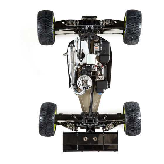
- Page 38 BAG H BAG H STEP H-07 Completed Chassis Assembly...
- Page 39 BEFORE RUNNING YOUR NEW 8IGHT OFF-ROAD RACING BUGGY for the fi rst time, you should run down the following check- list in order and complete the listed tasks. We’re sure you’re anxious to get out and run your new 8IGHT now that its built, but please note that fi...
- Page 40 “handle” go back to the kit (stock) setup, as this setup has proven to be reliable, consistent, and easy to drive. All of us at Team Losi are sure that you will fi nd the 8IGHT Off Road Racing Buggy to be the most versatile and easiest car to drive fast, with great consistency.
- Page 41 SETUP GUIDE SETUP GUIDE bite / smooth tracks, thick oil is easier to drive. Make sure you adjust oil when there is a drastic temperature change (20-25 degrees). If it gets cold outside you need to go to lighter shock oil. If it gets hotter outside you need to go to thicker weight shock oil. Front Toe: More front toe-in (longer steering rods) decreases steering response entering and in the middle of the turn.
- Page 42 SETUP GUIDE SETUP GUIDE Setup Notes: ____________________________________________________________________________________________________ ________________________________________________________________________________________________________________ _________________________________________________________________________________________________________________________________ _________________________________________________________________________________________________________________________________ _________________________________________________________________________________________________________________________________ _________________________________________________________________________________________________________________________________ ________________________________________________________________________________________________________________________________ ________________________________________________________________________________________________________________________________ ________________________________________________________________________________________________________________________________ ________________________________________________________________________________________________________________________________ ________________________________________________________________________________________________________________________________ ________________________________________________________________________________________________________________________________ ________________________________________________________________________________________________________________________________ ________________________________________________________________________________________________________________________________ ________________________________________________________________________________________________________________________________ ________________________________________________________________________________________________________________________________ ________________________________________________________________________________________________________________________________ ________________________________________________________________________________________________________________________________ ________________________________________________________________________________________________________________________________ ________________________________________________________________________________________________________________________________ ________________________________________________________________________________________________________________________________ ________________________________________________________________________________________________________________________________ ________________________________________________________________________________________________________________________________ ________________________________________________________________________________________________________________________________ ________________________________________________________________________________________________________________________________ ________________________________________________________________________________________________________________________________ ________________________________________________________________________________________________________________________________ ________________________________________________________________________________________________________________________________ ________________________________________________________________________________________________________________________________ ________________________________________________________________________________________________________________________________ ________________________________________________________________________________________________________________________________ ________________________________________________________________________________________________________________________________ ________________________________________________________________________________________________________________________________ ________________________________________________________________________________________________________________________________ ________________________________________________________________________________________________________________________________ ________________________________________________________________________________________________________________ ________________________________________________________________________________________________________________...
-
Page 43: Setup Sheet
SETUP SHEET SETUP SHEET Date: Name: Event: City: State: Track: Tight Smooth Blue Groove High Bite Track Hard Packed Low Bite Indoor Open Rough Conditions Outdoor Loose/Loamy Med Bite Other Dusty Front Suspension Ackerman Bump Steer Long Toe: Up Down Short Ride Height: Camber:... - Page 44 Bump Steer Toe: 1° Out Long Up Down Short Ride Height: 27mm Camber: -1° Caster: 20° Sway Bar: 2.32mm 55/35wt. Team Losi Piston/Oil: Outside Inside Spring: 4.4 Silver Limiter/Droop: 4.100” Overall Shock Length: Long Steering Ackerman: Bump Steer: Down Camber Link:...
- Page 45 HARDWARE HARDWARE Cap Head Flat Head 1 Flat Head 2 Button Head 2-56 x 1/4” (A6255) 2-56 x 1/4” (A6232) 3 x 8mm (A9104) 8-32 x 3/8” (A6264) 2-56 x 1/2” (A6254) 4-40 x 1/4” (A6234) 3 x 12mm (A3500) 4-40 x 3/8”...