
Summary of Contents for Soca ST-660
- Page 1 ST-660 PROXIMITY ACCESS CONTROL SYSTEM OPERATION AND INSTALLATION MANUAL SOCA TECHNOLOGY CO., LTD. 2000 July...
-
Page 2: Table Of Contents
CONTENTS SPECIAL FEATURES … … … … … … … … … … … … ..… … .....… ..1 FRONT PANEL AND TYPES OF CARDS ....… ....… … 1 III. INSTALLATION PROCEDURES … … … … … .… … … … … … … … … … ...3 SETTING MODE AND FUNCTIONS …... -
Page 3: Special Features
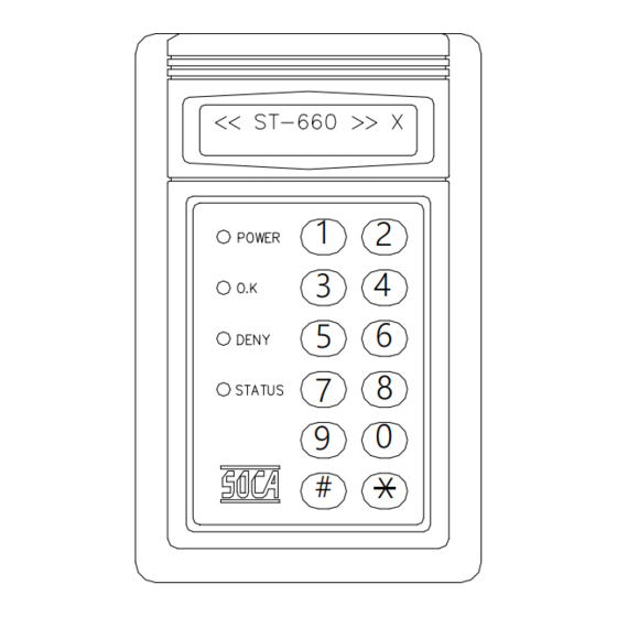
ST-660 Mode Setting SPECIAL FEATURES: 1. One set stand alone design. 2. After installation of proximity reader and connected to power source, the red power indicator on the front panel will brights up. After two seconds, there will be a “beep” sound . The display will show as follows: X means door identification mode. - Page 4 2. Ten digits input keys, two functional keys: “#”, “ * ”. # key: Confirmation key. * key: Clear or escape key. LCD display with back-light Power light (RED) Oaky light (GREEN) Deny light (YELLOW) Status light (YELLOW) Confirmation key Clear or escape key Types of proximity cards *...
-
Page 5: Installation Procedures
Then, observe for a beep immediately. sound and the screen will show “ ST-660 2 “ If yes, enter the system password ( # 5678#), then, observe a beep sound and that the yellow indicator flashes. If so, then it is in the setting mode. -
Page 6: Setting Mode And Functions
. SETTING MODES AND FUNCTIONS : For entering into the system setting mode, first press #, then press system password and press # subsequently to enter into system setting mode. By pressing # XXXX # (X X X X representing 4 digits system password). -
Page 7: Deletion And Loss Of Card (Delete One Card)
2. Delete to one car d : Deletion of user’ s card (such as loss card), card number is the 8 digits code indicated on the proximity card. SYSTEM FUNCTIONS SELECTION: ENTER STATUS LIGHT ON WILL BE SHOWN “ ” SYSTEM WITH A BEEP SOUND PRESS ON SCREEN... -
Page 8: Sets Of Door Access Passwords
3. Change the 8 sets of door openung passwor ds : SYSTEM FUNCTIONS SELECTION: ENTER STATUS LIGHT ON WILL BE SHOWN “ ” SYSTEM WITH A BEEP SOUND PRESS ON SCREEN PASSWORD “ ” CHANGE PASSWORDS NO: WILL BE SHOWN TERMINATE PRESS *... -
Page 9: Setting Identification Modes
5. Setting identification modes : There are four sets of door opening modes in the reader unit. But, it can only use one of them for setting the identification mode depending on the individual user’ s reader. In normal circumstances when this system is produced, the opening setting is set to card proximity. -
Page 10: Entire Batch Registration (Add Series Cards)
6. Entir e batch enter ing : To be used for registering multiple cards and cards in series. Enter 8 digits card number, then enter card quantity, in 4-digits manner (must be in full 4 digits, such as 100 pcs., enter 0100 ). Beside this function, this system can also apply to single card entry. -
Page 11: Anti-Damage Output Setting
7. Anti-damage output setting : This reader has a anti-damage output connecting point. There are two detection sources (1) Damage to the proximity reader(tamper switch). (2) Damage to the door (must add detection wiring such as reed switch). This function can be set whether door detection point is to be applied to activate the anti-damage output: (1) O : ON (2) I : OFF... -
Page 12: Deletion To The 8 Sets Of The Door Opening Passwords
9. Deletion on the 8 sets of door opening passwor ds : Please note that this function will clear the 8 set of door opening passwords and cannot be recovered . SYSTEM FUNCTIONS SELECTION: ENTER STATUS LIGHT ON WILL BE SHOWN “... -
Page 13: Door Opening (Using System Password)
11. Door opening (using system passwor d) : SYSTEM FUNCTIONS SELECTION: ENTER STATUS LIGHT ON WILL BE SHOWN “ ” SYSTEM WITH A BEEP SOUND PRESS ON SCREEN PASSWORD “ ” OPEN DOOR PRESS WILL BE SHOWN TERMINATE OPEN DOOR ON SCREEN 12. -
Page 14: Installation Of Proximity Reader
INSTALLATION OF PROXIMITY READER : 1. Reader connections : ST-660 Wiring diagram Purple Purple BLUE BLUE Door detection sensor point 2 Door detection sensor point 2 Green Green Door detection sensor point 1 Door detection sensor point 1 Yellow Yellow... -
Page 15: Installation Of Electric Lock And Exit Push Buttom
2. Installation of eletric lock and exit push button : A. Electr ic lock (fail secur e type) and r eader . A. Electr ic lock (fail secur e type) and r eader . ELECTRIC LOCK ELECTRIC LOCK EXIT PUSH EXIT PUSH YELLOW YELLOW... -
Page 16: Installation Of Door Sensor, External Relay And Siren
3. Installation of door sensor, external relay and siren : P. 13 A.Installation of r eed switch (nor mal close), exter nal r elay(anti-damage) A.Installation of r eed switch (nor mal close), exter nal r elay(anti-damage) 6Pin 6Pin 8Pin 8Pin REED(N.C) REED(N.C) N. -
Page 17: Precautions
P.S : (1) Proximity reader provides two external relay connecting points which are : A. Anti-damage ( tamper switch and door sensor ) alarm output connecting point ( 8P orange connecting point ). B. Duress alarm output connecting point ( 8P yellow connecting point ). - Page 18 1. Can sense the card but the door lock doesn’ t work? Remedy: (1) Please check whether there is power supply on the proximity reader and the eletric lock. (2) If it is okay, please check the electric lock power supply and whether the connecting points are correct.
- Page 19 Remedy : Enter into the system setting mode or open the door. 5. What is the operation of the door sensor detection (reed switch)? Remedy : If the door sensor detection function is being set at ON (for detail, refer to item 7 of the setting mode functional selection in the manual) and if the door is not closed within 30 seconds, then the anti-damage output function will be executed.