Table of Contents
TopPage
MODELS
CHAPTER 1. SPECIFICATION
[1]
Specification.................................... . ....... 1-1
[2]
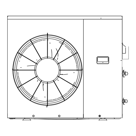
External Dimension....................... . ....... 1-2
[3]
Capacity Table ................................. . ....... 1-2
[4]
Electrical Parts ............................ . ....... 1-3
[5]
Wiring Diagrams.............................. . ....... 1-4
CHAPTER 2. EXPLANATION OF CIRCUIT AND OP-
ERATION
[1]
Block Diagarm ................................. . ....... 2-1
[2]
Function............................................. . ....... 2-2
CHAPTER 3. FUNCTION AND OPERATION OF PRO-
TECTIVE PROCEDURES
[1]
PROTECTIVE FUNCTIONS AND OPERA-
TIONS .................................................... . ....... 3-1
[2]
Troubleshooting Guide............... . ....... 3-3
Parts marked with "
" are important for maintaining the safety of the set. Be sure to replace these parts with specified ones for maintaining the
safety and performance of the set.
SERVICE MANUAL
MULTI SPLIT TYPE
ROOM AIR CONDITIONERS
AE-XM24HR
In the interests of user-safety (Required by safety regulations in some
countries) the set should be restored to its original condition and only
parts identical to those specified should be used.
CONTENTS
S6721AEXM24HRT
[1]
REFRIGERATION SYCLE.............................4-1
[2]
Performance Curves...........................4-3
[1]
OUTDOOR UNIT ...........................................5-1
This document has been published to be used for
after sales service only.
The contents are subject to change without notice.
Table of Contents

Related Manuals for Sharp AE-XM24HR


Summary of Contents for Sharp AE-XM24HR
-
Page 1: Service Manual
S6721AEXM24HRT MULTI SPLIT TYPE ROOM AIR CONDITIONERS OUTDOOR UNIT AE-XM24HR MODELS In the interests of user-safety (Required by safety regulations in some countries) the set should be restored to its original condition and only parts identical to those specified should be used. -
Page 2: Specification
AEXM24HR CHAPTER 1. AEXM24HR SPECIFICATION Service Manual [1] SPECIFICATION MODEL INDOOR UNIT OUTDOOR UNIT ITEMS AY-XPM7FR/9FR/ AE-XM24HR X12FR Cooling capacity 4-INDOOR OPERTION 7K&7K&7K&7K 7.0(3.0–8.2)* Heating capacity 4-INDOOR OPERTION 7K&7K&7K&7K 8.0(3.0–9.2)* Moisture removal (at cooling)✩ Liters/h 1.0X2&0.8* Electrical data Phase Single... -
Page 3: External Dimension
AEXM24HR [2] EXTERNAL DIMENSION 51.3 Figure OUTDOOR UNIT [3] CAPACITY TABLE 1. Recommended Combination Outdoor Indoor Units Units 7:AY-XPM7FR,GS-XPM7FR 9:AY-XPM9FR,GS-XPM9FR,GS-XPM9FGR 12:AY-XPM12FR,GS-XPM12FR,GS-XPM12FGR AE-XM24HR 1 – 2... -
Page 4: Electrical Parts
AEXM24HR 2. COOLING CAPACITY TABLE Running Current Power Consumption Combination of Indoor Units Cooling Capacity (kW) Oper- ating RATING (Min.- RATING (Min.- Status Max.) Max.) RATING (Min.-Max.) 1.75 1.75 1.75 1.75 7.0 (3.0-8.2) 10.0 (2.7-13.6) 2180 (600-2980) 2.40 1.80 1.40 1.40 7.0 (3.0-8.2) 10.0 (2.7-13.6) -
Page 5: Wiring Diagrams
AEXM24HR [5] WIRING DIAGRAMS 1. FOR MODEL AEXM24HR CC373 1 – 4... - Page 6 AEXM24HR 2. PRINTED WIRING BOARD 1 – 5...
-
Page 7: Printed Wiring Board
AEXM24HR 3. PRINTED WIRING BOARD from ELECTROLYTIC CAPACITOR C10(+) from CONTROL PWB CN14 from ELECTROLYTIC CAPACITOR C10(-) from COMPRESSOR TERMINAL W "ORANGE" from COMPRESSOR TERMINAL TERMINAL from COMPRESSOR U "RED" V "WHITE" from CONTROL PWB BCN1 figure IPM P.W.B 1 – 6... - Page 8 AEXM24HR 4. ELECTRONIC CONTROL CIRCUIT DIAGRAM 1 – 7...
-
Page 9: Eration 1] Block Diagarm
AEXM24HR CHAPTER 2. AEXM24HR EXPLANATION OF CIRCUIT AND OPERATION Service Manual [1] BLOCK DIAGARM 20 A Fuse Fuse Power supply Smoothing Active filter Filter AC power circuit circuit circuit circuit CPU oscillator circuit DC power supply circuit DC over voltage detection circuit Expansion valve A Expansion valve A... -
Page 10: Function
After that , the frequency is lowered approximately 5Hz once every Cooling mode Heating mode 60 seconds or approximately 15Hz once every 90 seconds. AE-XM24HR 16.5A 16.5A When the temperature of all of indoor heat exchangers go below the (2) Prevention control of outdoor heat exchanger overheating... - Page 11 AEXM24HR compressor is stopped, if the temperature is below 85°C,another When the indoor unit of a room requests for the cooling operation to starting try will be made. Three retries are allowed. On the fourth the outdoor unit and it runs responding to the request, retry, a complete stop request signal is sent to the indoor unit, requests for the heating can't be accepted if the indoor units in other and the outdoor unit will remain stopped until the indoor operation is...
- Page 12 AEXM24HR More than More than More than 20 min. 20 min. 20 min. Heating operation start Defrosting Defrosting Max. 10 min. Max. 10 min. (3) During defrosting When defrosting begins, the compressor stops. Approximately 1 minutes later, the compressor reactivates in the refrigeration cycle, and the outdoor heat exchanger is defrosted.
-
Page 13: Active Filter Circuit
AEXM24HR 2. Active Filter Circuit This circuit uses active filter and IPM as the figure below for the high efficiency operation of compressor. Active filter Choke coil Rectifica- tion circuit Comp Noise filter ressor circuit Positional detection Voltage raise Sine wave current ON/OFF signal Compressor... - Page 14 AEXM24HR Control Control IGBT IGBT PFC control PFC control BCN13 BCN13 Active Filter Circuit Active Filter Circuit 2.3. Active Filter Driving Electronics Circuit At the operation of compressor, the microcomputer (IC1), as the 50th pin gets “H”, will turn the transistor Q4 ON through the transistor Q3. By this, 18V is supplied to the 3rd pin of connector BCN13 of the active filter and the active filter will be turned ON.
- Page 15 AEXM24HR 1. Brief explanation of bootstrap system (single power drive system) To supply power to the upper-phase IC, the microcomputer (IC1) turns ON the lower-phase IGBT (LU, LV, LW). It results in a charging current that flows through the electrolytic capacitor in each upper-phase IC input and charges the bootstrap capacitor up to 15V voltage.
- Page 16 AEXM24HR microcomputer works in an internal processing so that detection is enabled only when it is ON. Based on the position signal detected, actual PWM waveform output timing is determined. Since it does not use a filter circuit, the accuracy of detection. The microcomputer works in an internal processing to eliminate spiky voltage during the regenerative process.
- Page 17 AEXM24HR FUSE 101 250V 20A C121 630v 0.33 R201 100KF R202 R113 18KF 20KF R100 C119 0.015 1000p ZD101 R200 R203 2.0KF 1000P 0.1μ R204 200KF R205 200KF Inverter current detection circuit 2 – 9...
-
Page 18: Protective Functions And Opera Tions
CHAPTER 3. FUNCTION AND OPERATION OF PROTECTIVE PROCEDURES [1] PROTECTIVE FUNCTIONS AND OPERATIONS FUNCTION AND OPERATION OF PROTECTIVE PROCEDURES Function Operation Description Detection time Restart condition Restarts door door time Compressor is stopped if a current DC over During Automatically 4 times Yes approximately 50A or more flows current... - Page 19 NO. Function Operation Description Detection time Restarts condition Restarts time door door During Automatically Compressor is stopped, if the oper- 4 times Yes starts after safety compressor ating frequency is above 70Hz and abnormal operation time (180 seconds) the compressor current is below current 0.8A.
-
Page 20: Troubleshooting Guide
[2] TROUBLESHOOTING GUIDE T R OUB L E S HOOT ING G UIDE 1. S E L F -DIA G NOS IS F UNC T ION A ND DIS P L A Y MODE (1) T o call out the content of the s elf-diagnos is memory, hold down the emergency operation button for more than five s econds when the indoor unit is not operating. - Page 21 3 – 4...
- Page 22 3 – 5...
- Page 23 CHECK METHOD (OUTDOOR) CAUTION IN CHECKING PRINTED CIRCUIT BOARDS (PWB) Non-insulated control circuit The GND terminals of the low-voltage circuits (control circuits for microcomputer and thermistors and drive circuits for expansion valve and relays) on the control printed circuit board (PWB) are connected to the compressor drive power supply (370-VDC negative terminal). Therefore, exercise utmost caution to prevent electric shock.
- Page 24 Figure 1 Cautions when attaching or removing the board When operating only the outdoor unit (cooling 55 Hz fixed mode) To make only the outdoor unit run in cooling mode, and apply a voltage of 220 ~ V AC to L and N on the terminal board and push the PUMP DOWN SWITCH (SW1).
- Page 25 Figure 2 Temperature properties of outdoor thermistors Connector Connector CN8A CN8C TH2 : Heat exchanger pipe thermistor (CN8A 3 - 4 ) TH3 : Outdoor temp. thermistor (CN8A 5 - 6 ) TH4 : Suction thermistor (CN8A 7 - 8 ) TH6 : Thermistor unit A (CN8C 1 - 2 ) TH7 : Thermistor unit B (CN8C 3 - 4 ) TH8 : Thermistor unit C (CN8C 5 - 6 )
- Page 26 3 – 9...
- Page 27 3 – 10...
- Page 28 3 – 11...
- Page 29 3 When all rooms are not heated Does the air get cooler in the Ye s cooling operation mode? Refer to 1 All rooms are Press the ON switch on the not cooled. remote control to run the air conditioner. Set the temperature to 32 in the heating mode and start operation.
-
Page 30: Chapter 4. Refrigeration Cycle 1] Refrigeration Sycle
AEXM24HR CHAPTER 4. AEXM24HR REFRIGERATION CYCLE Service Manual [1] REFRIGERATION SYCLE 1. class indoor unit is connected UNITA UNIT D S TOP valve (Liquid) E xpansion valve D Heat exchanger UNIT C E xpansion valve C Heat exchanger UNIT B E xpansion valve B Heat exchanger UNIT A... - Page 31 AEXM24HR 2. Cycle temperature and pressurre in stop valve (AEXM24HR) Running unit opration mode Cool(MAX) Cool(Test run) Heat(MAX) Heat(Test run) & & stop valve 1.12MPa(abs) 1.23MPa(abs) 2.33MPa(abs) 1.80MPa(abs) & (gas saide) Frequency 100Hz 55Hz 110Hz 50Hz (4 units) (1 unit) stop valve pressure 0.90MPa(abs) 1.08MPa(abs)
-
Page 32: Performance Curves
AEXM24HR 3. PERFORMANCE CURVES NOT E : T otal cooling capacity and total input with 4 units running. (R unning frequency: HZ) (R unning frequency: HZ) 2600 2400 2200 2400 2000 2200 1800 2000 1600 1800 Outside air temp. Outside air temp. F ig. - Page 33 AEXM24HR Gauge manifold Compound gauge Hose Service port Stop valve (gas side) Stop valve (liquid side) Vacuume pump adapter Service port Hexagon socket screw key Valve shaft cap OPEN Pump down (Pump down is adopted in the case of unit removal for re installation, abandonment, repair etc.) Pump down is to collect the refrigerant into the outdoor unit by control of the stop valves and the compressor.
- Page 34 AEXM24HR MISWIRING CHECK Miswiring check must be performed after installation, reinstallation and service. UNIT B UNIT B UNIT A UNIT A LED 2 LE D 2 LED 1 LE D 1 This multi-type air conditioner is designed with a WIRE CHECK SWITCH on the outdoor unit, and miswiring of unit-to-unit LED 4 LE D 4...
- Page 35 AEXM24HR CHAPTER 5. AEXM24HR DISASSEMBLING PROCEDURE Service Manual [1] OUTDOOR UNIT 4) Remove the 6 screws fixing the rear guard. 1) Remove the 5 screws fixing the front panel R and slide the front panel R down. 5) Remove the 11 screws fixing the side cover R. 2) Remove the 10 screws fixing the top cover.
- Page 36 AEXM24HR 9) Disconnect the 7 connectors. 12)Remove the 5 screws fixing the controlbox assembly. Fan motor / Reverse valve Thermistor/ Expansion valve 13).Cut the2 insulators. C ut 10)Remove the compressor cover. Compressor cover 11)Remove the terminal cover and disconnect 3 terminals. 14)Remove the 3 screws fixing the bulkhead.
- Page 37 AEXM24HR 15)Remove the 1 nut fixing the propeller fan. 19)Position of the thermistors Note :Caution to the position when reinstalling. L oos e G reen 16)remove the 2 screws fixing the motor angle. Orange B lack 17)Cut the fixing bands. Yellow 18)Remove the 4 screws fixing the fan motor.
- Page 38 AEXM24HR 20)How to disassemble the control box assembly 1.Cut the wire fixing band.(3 points) 2. Remove the 4 screws fixing the PWB. 3. Unlock the spacer's lock. Instal this SHORT-CIRCUIT CONNECTOR in a new CONTROL PWB at CONTROL PWB exchange. 5 –...
- Page 39 AEXM24HR 5 – 5...
- Page 40 AEXM24HR 5 – 6...
- Page 41 AEXM24HR PartsGuide PARTS GUIDE MALTI SPLIT TYPE ROOM AIR CONDITIONERS OUTDOOR UNIT AE-XM24HR MODELS CONTENTS CONTROL BOX PARTS PACKING PARTS CABINET AND PARTS ACCESSORY PARTS CYCLE PARTS INDEX OTHER PARTS Parts marked with " " are important for maintaining the safety of the set. Be sure to replace these parts with specified ones for maintaining the safety and performance of the set.
- Page 42 AEXM24HR PARTS CODE P R I C E N E W P A R T DESCRIPTION RANK MARK RANK [1] CONTROL BOX PARTS LEAD WIRE (TB-CN6) QW-VZF873JBZZ LEAD WIRE (TBN-TBN) QW-VZF814JBZZ LEAD WIRE (TB1-TB1) QW-VZF815JBZZ LEAD WIRE (TBE-TBE) QW-VZF816JBZZ 1-10-1 LEAD WIRE (TBN-L3-1) QW-VZF817JBZZ 1-10-2...
- Page 43 AEXM24HR [2] CABINET AND PARTS 2-37 2-23 2-70 1-45 2-40 1-71 1-44 2-24 2-26 1-48 2-25 2-20 1-60 2-17 2-28 1-12 1-66 2-20 2-19 1-58 1-36 2-55 1-66 1-63 1-76 2-38 1-52 2-41 1-11 1-62 1-62 1-5-2 1-61 3-15 1-65 2-39 1-70 2-31...
- Page 44 AEXM24HR PRICE PART PARTS CODE DESCRIPTION RANK MARK RANK [2] CABINET AND PARTS FAN MOTOR CMOTLB051JBEZ TERMINAL BOARD ANGLE LANG-A540JBWZ CORD HOLDER LHLD-A539JBFA CORD CLAMP HOLDER LHLD-A544JBFA 1-5-1 TERMINAL BOARD QTANZA044JBZZ 1-5-2 TERMINAL BOARD QTANZA021JBZZ 1-11 CONTROL BOX ASS'Y DBOX-A044JBWZ 1-12 CONTROL BOARD UNIT DSGY-C285JBKZ...
- Page 45 AEXM24HR [3] CYCLE PARTS 3-14 3-21 2-34 3-35 3-25 1-69 3-24 3-10 1-54 3-17 1-78 2-35 2-33 3-12 3-1-1 3-23 3-17 1-73 3-1-1 3-17 3-1-1 3-17 3-22 2-67 2-69 3-13 3-1-1 2-68 3-33 3-11 3-31 3-34 3-30 2-30 3-32 3-28 3-34 2-66 2-30...
- Page 46 AEXM24HR PRICE PART PARTS CODE DESCRIPTION RANK MARK RANK [3] CYCLE PARTS 1-54 COMPRESSOR CORD QW-IZA112JBZZ 1-69 THERMISTOR ASS'Y RH-HXA081JBZZ 1-73 THERMISTOR RTHM-A022JBE0 1-78 THERMISTOR RH-HXA092JBZZ 2-16 FLARE COUPLING BASE PDAI-A177JBTB 2-30 FLARE CUP.SUB-S LSUB-A020JBWZ 2-33 THERMISTOR SPRING MSPR-A026JBE0 2-34 THERMISTOR SPRING MSPR-A036JBE0 2-35...
- Page 47 AEXM24HR PRICE PART PARTS CODE DESCRIPTION RANK MARK RANK [5] PACKING PARTS BOTTOM PAD ASS'Y CPADBA072JBKZ PACKING PAD ASS'Y CPADBA073JBKZ PACKING CASE SPAKCC381JBEZ [6] ACCESSORY PARTS 6-10 6-10 6-10 PRICE PART PARTS CODE DESCRIPTION RANK MARK RANK [6] ACCESSORY PARTS INSTALLATION MANUAL TINS-B107JBRZ INSTALLATION MANUAL...
- Page 48 AEXM24HR INDEX PRICE PART PRICE PART PARTS CODE PARTS CODE RANK MARK RANK RANK MARK RANK PCON-A553JBPZ 2-3-15 [ C ] PCOV-0562JBE0 3-3-14 CCHS-A862JBKZ 2-2-14 PCOV-A940JBWZ 2-2-37 CCIL-A112JBEZ 3-3-8 PDAI-A177JBTB 3-2-16 CMOTLB051JBEZ 2-1-1 PGUM-A119JBEZ 3-2-67 CPADBA072JBKZ 5-5-1 PGUM-A120JBEZ 3-2-68 CPADBA073JBKZ 5-5-2 PGUM-A121JBEZ 3-3-24...
- Page 49 AEXM24HR PRICE PART PARTS CODE RANK MARK RANK [ S ] SPAKCC381JBEZ 5-5-3 [ T ] TINS-B107JBRZ 6-6-1 TINS-B108JBRZ 6-6-1 TINS-B109JBRZ 6-6-1 TLAB-B709JBRA 3-2-64 TLABBA146JBRA 2-2-52 TLAB-C770JBRA 3-2-63 TLAB-C773JBRZ 2-2-62 TLABCC373JBRZ 2-2-53 TLAB-D231JBRZ 4-1-90 TLAB-D234JBRZ 2-2-61 TLAB-D247JBRZ 4-1-86 TLAB-D257JBEZ 2-2-70 TSPC-F845JBRZ 2-2-55 [ V ]...
- Page 50 © COPYRIGHT XXXX BYSHARP CORPORATION ALL RIGHTS RESERVED. No part of this publication may be reproduced, stored in a retrieval system, or transmitted in any form or by any means, electronic, mechanical, photocopying, recording, or otherwise, without prior written permission of the publisher. –...