Table of Contents
Quick Links
Table of Contents

Related Manuals for Philips SL ParBlazer 100 UV


Summary of Contents for Philips SL ParBlazer 100 UV
- Page 1 SL ParBlazer 100 UV...
-
Page 2: Showline Offices
Showline. Its sole purpose is to provide the user with conceptual information on the equipment mentioned. The use of this document for all other purposes is specifically prohibited. Document Number: SL ParBlazer 100 UV User’s Manual Version as of: 9th Mar, 2015 Rev1.0 SL ParBlazer 100 UV Installation &... -
Page 3: Warnings And Notices
SL ParBlazer 100 UV Installation & User’s Manual IMPORTANT INOFRMATION Warnings and Notices When using electrical equipment, basic safety precautions should always be followed including the following: READ AND FOLLOW ALL SAFETY INSTRUCTIONS. Do not mount near gas or electric heaters. -
Page 4: Table Of Contents
Included Items SL ParBlazer 100 UV OVERVIEW SL ParBlazer 100 UV Components INSTALLATION AND SET UP Connecting Power Connecting SL ParBlazer 100 UV to AC Power Connecting to the DMX512 Network Mounting Luminaire Truss / Hanging Applications Floor Mounting OPERATION AND PROGRAMMING... -
Page 5: Preface
Please read all instructions before installing or using this product. Retain this manual for future reference. Additional product information and descriptions may be found on the product specification sheet. Note: The SL ParBlazer 100 UV luminaire works from 100 to 240 VAC (auto-ranging). Included Items... -
Page 6: Sl Parblazer 100 Uv Overview
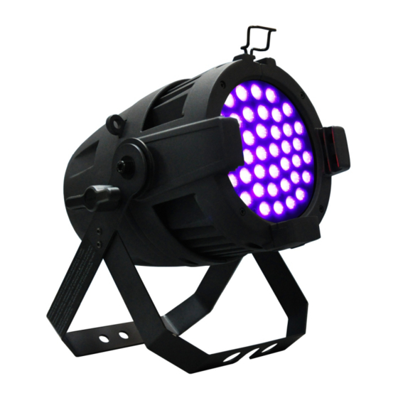
AC Input DMX512/ DMX512 / RDM Input RDM Output UV LEDs Figure 1: SL ParBlazer 100 UV Common Components LCD Display / Menu System EXIT Button CHECK MARK(OK) Button RIGHT Arrow Button LEFT Arrow Button Figure 2: LCD Display & Menu System "LCD Display and Menu System"... -
Page 7: Installation And Set Up
The SL Pa rBlazer 100 UV Luminaire operates on AC input voltages from 100 to 240 VAC. W ARN ING! The SL ParBlazer 100 UV luminaire does not have an ON/OFF switch. Always disconnect power input cable to completely remove power from the luminaire when not in use. - Page 8 Connecting SL ParBlazer 100 UV to AC Power Table 2 describes how to connect power to your SL ParBlazer 100 UV. Field wiring of the SL ParBlazer 100 UV LED Luminaire is straightforward. A total of 3 wires/conductors need to be brought to the unit.
-
Page 9: Connecting To The Dmx512 Network
"daisy-chain" fashion. A cable runs from the control console (or DMX512 control source) to the DMX connector on the first SL ParBlazer 100 UV. Another cable runs from the other DMX connector on the first unit to a DMX connector on the next SL ParBlazer 100 UV (or DMX512 device to be controlled). -
Page 10: Mounting Luminaire
Truss / Hanging Applications The SL ParBlazer 100 UV is provided with the ability to hang via truss hooks, clamps, etc. (sold separately). Simply attach hook, clamp, etc. to the SL ParBlazer 100 UV yoke in the provided M12 holes. It is recommended (and may be required by local and national safety codes) to use and install a safety cable (sold separately) as illustrated in Figure 6. -
Page 11: Operation And Programming
SL ParBlazer 100 UV Installation & User’s Manual OPERATION AND PROGRAMMING 1. LCD Display and Menu System The SL PARBLAZER Luminaire’s LCD Display and Menu System provides local control for accessing the following fixture’s settings: DMX Address Manual Dimming DMX Personality... -
Page 12: Lcd Display And Menu System Operation
Installation & User’s Manual SL ParBlazer 100 UV 2. LCD Display and Menu System Operation The LCD Display Menu system consists of several categories. Use the Menu Buttons to access and make changes to the menu items. When the desired menu item is reached, press the desired Menu Button to display the menu options and to navigate and configure the menu options as required. -
Page 13: Sl Parblazer 100 Uv Menu Tree
DMX 8Bit DMX 16Bit Manual Dimming Curve Linear Curve Square Curve S_Curve PL_Curve DMX Fail Last Hold Manual Default Setting Temperature 55^oC Firmware Rev1.00 RDM UID 0x405101020304 Figure 9: SL ParBlazer 100 UV Menu Tree SL ParBlazer 100 UV Menu Tree... -
Page 14: Master / Slave Operational Mode
4. Master / Slave Operational Mode The Master / Slave Operational Mode allows one SL ParBlazer 100 UV to act as the "Master" unit and all other connected units are controlled by this unit. When a unit is set to "Slave" mode, it will only listen to and follow any commands sent from a "Master"... -
Page 15: Dimming Curve Selection
S_Curve Square Curve Linear Curve PL_Curve * DMX Value DMX Value *PL Curve follows the dimming curve of Philips Selecon PL series LED luminaries. S_Curve Square Curve DMX Value DMX Value Figure 9: SL ParBlazer 100 UV Luminaire Dimmer Curves... -
Page 16: Dmx Control
SL ParBlazer 100 UV DMX Mapping 8-Bit Mode Table 3 provides DMX channel mapping of all DMX512 control values when the SL ParBlazer 100 UV LED Luminaire is in 8-bit DMX512 mode (as set by the luminaire’s menu system). Table 3: SL ParBlazer 100 UV DMX Channel Mapping ( 8 - Bit Mode) -
Page 17: Rdm Parameter Ids
Installation & User’s Manual 1. SL ParBlazer 100 UV RDM Parameter IDs The following tables outline and describe all the RDM parameters Ids associated with SL ParBlazer 100 UV LED Luminaires. Table 5, “SL ParBlazer 100 UV RDM Product Parameters IDs”... - Page 18 Installation & User’s Manual SL ParBlazer 100 UV Table 7: SL ParBlazer 100 UV RDM Parameters IDs RDM Parameter IDs Value Comment Implemented Allowed Allowed Category - Product Information DEVICE_INFO 0x0060 PRODUCT_DETAIL_ID_LIST 0x0070 DEVICE_MODEL_DESCRIPTION 0x0080 MANUFACTURER_LABEL 0x0081 DEVICE_LABEL 0x0082 FACTORY_DEFAULTS...
- Page 19 PRESET_PLAYBACK 0x1031 Table 8: SL ParBlazer 100 UV RDM Parameter Status IDs Manufacturer Specific messages are in the range of 0x8000 - 0xFFDF. Each Manufacturer-specific Status ID shall have a unique meaning, which shall be consistent across all products having a given Manufacturer ID. See Table B-2, ANSI E1.20-2010...
-
Page 20: Cleaning And Care
WARNING! Under no circumstances should ammonia-based cleaners, acetone, or other harsh solvents be used on or near the SL ParBlazer 100 UV. These types of cleaners or solvents can permanently damage the optics or housings of the fixture. -
Page 21: Technical Specifications
SL ParBlazer 100 UV Installation & User’s Manual TECHNICAL SPECIFICATIONS 1. OPERATIONAL SPECIFICATIONS Source: 40pcs High Power UV LED Array Beam Angle: 20 Degrees Light Output: 17,000 mW 40 degrees Field Angle: Input Voltage: 100V to 240V(+/- 10%, auto-ranging) Power Consumption: 100 Watts(max). -
Page 22: Luminaire Dimensions
Installation & User’s Manual SL ParBlazer 100 UV 2. Luminaire Dimensions LUMINAIRE DIMENSIONS... - Page 23 SL ParBlazer 100 UV Installation & User’s Manual NOTE...
- Page 24 2015 Philips Group...