Table of Contents
Illustration: CD-BK1600V
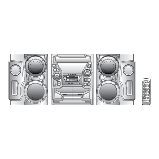
Illustration: CD-BK1800V
Illustration: CD-BK190V
Safety Precaution For Service Manual ........................................................................................................... 2
Voltage Selection ..................................................................................................................................................... 2
Specifications ............................................................................................................................................................. 3
Names Of Parts ........................................................................................................................................................... 4
Operation Manual ...................................................................................................................................................... 6
Disassembly .................................................................................................................................................................. 8
Removing And Reinstalling The Main Parts ................................................................................................... 11
Adjustment ................................................................................................................................................................. 12
Notes On Schematic Diagram .............................................................................................................................. 15
Block Diagram ........................................................................................................................................................... 16
Schematic Diagram ................................................................................................................................................... 20
Wiring Side Of P.w.board ........................................................................................................................................ 31
Voltage ........................................................................................................................................................................ 39
Waveforms Of Cd Circuit ...................................................................................................................................... 40
TROUBLESHOOTING ..................................................................................................................................................... 41
Function Table Of Ic ................................................................................................................................................ 45
FL DISPLAY ...................................................................................................................................................................... 56
REPLACEMENT PARTS LIST/EXPLODED VIEW
SERVICE MANUAL
MODEL
MODEL
CONTENTS
SHARP CORPORATION
– 1 –
CD-BK1600V/1800V/190V
VIDEO CD MINI SYSTEM
CD-BK1600V
CD-BK1600V Video CD Mini System consisting of
CD-BK1600V (main unit) and CP-BK1600 (speaker system).
CD-BK1800V
CD-BK1800V Video CD Mini System consisting of
CD-BK1800V (main unit), CP-BK1800 (front speakers) and
GBOXS0041AWM1 (surround speakers).
CD-BK190V
MODEL
CD-BK190V Video CD
CD-BK190V (main unit), CP-BK190 (front speakers) and
GBOXS0041AWM1 (surround speakers).
• In the interests of user-safety the set should be restored to its
original condition and only parts identical to those specified be
used.
This document has been published to be used
for after sales service only.
The contents are subject to change without notice.
No. S5041CDBK1600
Mini
System consisting of
NTSC/PAL
Page
Table of Contents

Related Manuals for Sharp CD-BK1600V

Summary of Contents for Sharp CD-BK1600V
- Page 1 CD-BK1600V/1800V/190V SERVICE MANUAL No. S5041CDBK1600 VIDEO CD MINI SYSTEM CD-BK1600V MODEL CD-BK1600V Video CD Mini System consisting of CD-BK1600V (main unit) and CP-BK1600 (speaker system). Illustration: CD-BK1600V CD-BK1800V MODEL CD-BK1800V Video CD Mini System consisting of CD-BK1800V (main unit), CP-BK1800 (front speakers) and GBOXS0041AWM1 (surround speakers).
-
Page 2: Safety Precaution For Service Manual
CD-BK1600V/1800V/190V SAFETY PRECAUTION FOR SERVICE MANUAL Precaution to be taken when replacing and servicing the Laser Pickup. The AEL (Accessible Emission Level) of Laser Power Output for this model is specified to be lower than Class 1 Requirements. However, the following precautions must be observed during servicing to protect your eyes against exposure to the Laser beam. -
Page 3: Specifications
CD-BK1600V/1800V/190V FOR A COMPLETE DESCRIPTION OF THE OPERATION OF THIS UNIT, PLEASE REFER TO THE OPERATION MANUAL. SPECIFICATIONS CD-BK1600V/1800V/190V CP-BK1600V General 3-way [10 cm (4") woofer 2 and Type: 5 cm (2") tweeter] Power source: AC 110/127/220/230-240 V, 50/60 Maximum input... -
Page 4: Names Of Parts
CD-BK1600V/1800V/190V NAMES OF PARTS CD-BK1600V/1800V/190V Front panel 22 23 18 19 20 21 1. Disc Tray 24. (TAPE 2) Reverse Play Button 2. (VCD/CD) Karaoke Mode Button 25. (VCD) Stop/Return Button 3. (VCD) Playback Control Button (CD/TAPE) Stop Button 4. (VCD) On Screen Display On/Off Button 26. - Page 5 CD-BK1600V/1800V/190V Rear panel 1. AC Voltage Selector 2. AC Power Input Socket 3. FM 75 Ohms Aerial Terminal 4. FM Aerial Earth Terminal 5. AM Loop Aerial Terminal 6. Span Selector Switch 7. Video Output Socket 8. Video/Auxiliary (Audio Signal) Input Sockets 9.
-
Page 6: Operation Manual
CD-BK1600V/1800V/190V CD-BK1600V/1800V/190V Remote control 1. Remote Control Transmitter LED 2. Echo Level Up/Down Buttons 3. Karaoke Mode Button 4. Vocal Replacer Button 5. (VCD) VCD Auto/On Button 6. (VCD) Playback Control Auto/Off Button 7. (VCD) On Screen Display On/Off Button 8. - Page 7 CD-BK1600V/1800V/190V – 7 –...
-
Page 8: Disassembly
CD-BK1600V/1800V/190V DISASSEMBLY CD-BK1600V/1800V/190V Caution on Disassembly Follow the below-mentioned notes when disassembling Front Panel the unit and reassembling it, to keep it safe and ensure (A1)x2 Top Cabinet excellent performance: ø3x12mm 1. Take cassette tape and compact disc out of the unit. - Page 9 CD-BK1600V/1800V/190V (J2)x1 Clamp Lever Front Panel Display PWB (J1)x15 ø3x10mm Tape Mechanism Open Cam Gear Rib (K1)x6 ø3x10mm Cassette Holder(Lift/Right) (L1)x1 Headphones PWB ø3x10mm Figure 9-1 Figure 9-4 Record/ (M2) x1 Playback (E1)x2 ø3x10mm (E2)x1 Turntable Front Panel Tape (E5)x1...
- Page 10 CD-BK1600V/1800V/190V (Q2) x3 Disc Tray (P2)x2 Video CD Mechanism (P1)x3 (Q1) x1 (Q1) x1 Disc Tray (P2)x2 Figure 10-1 Figure 10-2 CP-BK1600/BK190 CP-BK1800 REMOVAL PROCEDURE FIGURE REMOVAL PROCEDURE FIGURE STEP STEP Woofer/ 1. Front Panel .... (A1) x1 10-3 Woofer/ 1.
-
Page 11: Removing And Reinstalling The Main Parts
CD-BK1600V/1800V/190V REMOVING AND REINSTALLING THE MAIN PARTS TAPE MECHANISM SECTION TAPE 2 Perform steps 1, 2, 3, 4, 5, 7, 8 and 10 of the disassembly method to remove the tape mechanism. Record/Playback Head How to remove the record/playback and erase heads (Tape 2) (See Fig. -
Page 12: Adjustment
CD-BK1600V/1800V/190V CD MECHANISM SECTION Perform steps 1, 2, 3, 11, 12, 13, 14 and 15 of the disassembly method to remove the CD mechanism. How to remove the T/T Up/Down motor T/T Up/Down Motor (See Fig. 12-1) Disc Tray 1. Bend the hooks (A1) x 5 pcs., to remove the T/T Up/Down motor. - Page 13 CD-BK1600V/1800V/190V TUNER SECTION • FM RF fL: Low-range frequency fH: High-range frequency Signal generator: 400Hz, 22.5 kHz dev., FM modulated • AM IF/RF Test Stage Frequency Frequency Setting/ Instrument Signal generator: 400 Hz, 30%, AM modulated Display Adjusting Connection Point...
-
Page 14
CD-BK1600V/1800V/190V • TEST MODE Setting of test mode Any one test mode can be set by pressing several keys as follows.
+ + TEST: CD operation test Function:-CD test mode. -Enter test mode. T E S T IL isn't done OPEN/CLOSE operation is using manual. -
Page 15: Notes On Schematic Diagram
CD-BK1600V/1800V/190V NOTES ON SCHEMATIC DIAGRAM • The indicated voltage in each section is the one measured • Resistor: by Digital Multimeter between such a section and the chas- To differentiate the units of resistors, such symbol as K and sis with no signal given. -
Page 16: Block Diagram
CD-BK1600V/1800V/190V 27MHz 4.19MHz 2127 3545 DQ15 MD11 DQ12 MD12 DQ11 MD15 ICV2 D61012GC ICV1 MPEG DECODER MPEG CONTROLLER IX0352AW MCAS MRAS 35 32 33 9597 98 99 JK671 VIDO OUT CNPV3 PICKUP IN UP/DOWN CNS4 CNP4 MOTOR 29 22 21 14... - Page 17 CD-BK1600V/1800V/190V TO MAIN SECTION (TO IC601) CNSK1 10 11 10 11 BIK1 36 35 42 41 40 12 13 VRK1 MIC1 VRK2 VOLUME MIC2 VOLUME PINK1 CHASIS MIC1 MIC2 Figure 17 BLOCK DIAGRAM (2/4) – 17 –...
- Page 18 CD-BK1600V/1800V/190V FM ANTENNA SO302 IC301 T302 CF303 TA7358AP BF301 X351 FM FRONT END CF351 AM MIX AM IF FM+B MO/ST T301 L312 IC303 LA1832S FM IF DET./ FM/AM FM MPX./AM IF MPXIN FM/AM 21 24 AM LOOP ANTENNA FM OSC...
- Page 19 CD-BK1600V/1800V/190V R. PLAY SW401 FL701 F. PLAY SPAN SELECTOR FL DISPLAY T2 PLAY T1 PLAY 21 36 Q604 SOLENOID Q608 MOTOR TAPE DRIVER MOTOR Q601-Q603 Q607 Q606 LED722 Q605 60 5857 5655 54 5352 49 48 4746 44 4342 4140...
-
Page 20: Schematic Diagram
CD-BK1600V/1800V/190V KTA1298 Y 1SS133 RV84 4.7K KTA1298 Y RV85 47/6.3 3.3V KRC104 S KDS193 C2PO LRCK BCLK DATAD MBUSY AV_GND D_GND MCLK RV86 4.7K 9 8 7 6 5 4 3 2 16 15 14 13 12 11 10 RV93... - Page 21 CD-BK1600V/1800V/190V CD VIDEO PWB-B(1/2) VIDEO SIGNAL RV64 RV95 CV39 RV62 6.8K 1000/6.3 ICV4 RV63 NJM2267M VIDEO OPERATION AMP. CV40 22/6.3 CV41 4.7/25 FROM MAIN PWB P27 10-B RV96 CV17 0.01 CNS404 CV183 30/6.3 CNPV3 CV15 RV61 4.7/25 100K RV60 CV11 0.22...
- Page 22 CD-BK1600V/1800V/190V CD VIDEO PWB-B(2/2) CD SIGNAL Vref TIN1 FIN1 0.047 FIN2 TIN2 LA9236M 1.5M C24 SERVO AMP. 47/6.3 2.2/50 FIN1 CNP1 0.022 ODRV RFSW FIN2 120K AGCON TIN1 RF– TIN2 100/6.3 0.01 REF1 0.0047 VREF 0.33 0.047 ODRV 10/35 RFEV PH/BH FE–...
- Page 23 CD-BK1600V/1800V/190V C71 100P R71 1K C72 0.01 R72 1K C73 100P R73 1K C74 100P R74 1K KTA1266GR C75 100P R75 1K SERVO/SIGNAL C76 100P R76 1K CONTROL C77 100P R77 1K C78 100P R78 1K 2.2µH EFMO VDD5V 0.047 0.022...
- Page 24 CD-BK1600V/1800V/190V DISPLAY PWB-A2 FL701 FL DISPLAY Q602 Q603 KTC3199 GR KTC3199 GR C616 C609 1/50 47/50 82 83 84 85 87 88 89 92 93 94 95 97 98 99 VLOAD NO USE R677 S-BUSY R678 T-BIAS R679 T_T1/T2 R680...
- Page 25 CD-BK1600V/1800V/190V CNS701 BI701 CD INT WRQ(DSP) P23 12-E CD CE CD DO CD VIDEO PWB CD DI CNP12 CD CLK RES OUT CLAMP SW 89 90 92 93 94 95 97 98 99 S_BUSY NO USE R677 M_BUSY S-BUSY R678...
- Page 26 CD-BK1600V/1800V/190V IC401 LC75341 AUDIO PROCESSOR CNS402 R-CH A_GND P23 12-D L-CH C407 C408 CNP11 CD_GND 10/50 10/50 TO CD VIDEO VREF INTERFACE C409 0.1(ML) C410 LOUT ROUT R401 R409 0.1(ML) R415 BI402 C411 0.1(ML) 3.9K C412 0.1(ML) RBASS LBASS Q401 C414 0.0027...
- Page 27 CD-BK1600V/1800V/190V R421 L-ch R419 C429 SO401 4.7K 390P VIDEO/ AUX IN R420 C430 R426 C406 C408 390P 4.7K R422 22/25 R-ch 10/50 CNS404 BI404 JK671 C410 D403 VIDEO OUT 0.1(ML) CNPV3 R416 DS1SS133 C412 0.1(ML) 3.9K CD VIDEO C414 0.0027...
- Page 28 CD-BK1600V/1800V/190V IC901 STK40204 POWER AMP.(2Ch) FM SIGNA C902 220P C903 R918 R919 C911 C912 C901 10/50 10/50 R920 220P (1/4W) (1/4W) R901 C910 R905 100/50 R903 R904 R931 C906 C905 47/50 47/50 R933 R934 R907 0.1(1W) R908 0.1(1W) D901 D903...
- Page 29 CD-BK1600V/1800V/190V CNS971 C971 FM SIGNAL 47/50 R975 D971 R971 (1/2W) M901 DS1SS133 FAN MOTOR R973 C972 R972 10/50 R953 RL951 R954 FW951 4.7K 4.7K R952 330(1/2W) R951 JK951 330(1/2W) HEADPHONES D951 Q951 DS1SS133 HEADPHONES PWB-A3 KRC107 M L921 0.29µH SP_L Ch...
- Page 30 CD-BK1600V/1800V/190V AM LOOP ANTENNA SO302 FM TERMINAL CNP302 MAIN PWB-A1(3/3) C301 C375 0.01 0.001 C314 D305 DS1SS133 FM SIGNAL 0.0047 C303 C308 10P (CH) 4.7P C338 C304 C315 FM RF AM SIGNAL L312 C302 0.001 0.01 0.0047 0.001 C309 C316 D301 0.001...
-
Page 31: Wiring Side Of P.w.board
CD-BK1600V/1800V/190V KARAOKE PWB-G MIC SIGNAL ICK1 PINK1 M65856SP 1SS133 CK35 MIC AMP. RK11 CHASIS 0.01 MICSW DATA 1SS133 RK10 1K CK34 MCLKCONT CLOCK MIC2 VALC LATCH 0.47 MIC1IN CK33 4.7/50 ALC1 5.6K VRK2 CK31 0.15 2.2/50 MIC1NFIN VCFIL 20K(B) CK29 2.2/50... - Page 32 CD-BK1600V/1800V/190V P31 8 - H TO VIDEO CD TO KARAOKE PWB CNS404 CNSK1 P36 1-A CNPV3 R378 R374 R372 X352 C302 R373 R388 C382 1 2 3 4 5 6 7 8 9 1011 C395 C381 IC302 R376 C387 R379...
- Page 33 CD-BK1600V/1800V/190V DISPLAY PWB CNP702 P35 9-H CNS402 TO VIDEO CD FC701 P36 3-A CNP11 R423 R409 Q110 R142 B C E C138 C423 R132 R136 R124 C425 R139 C134 1 2 3 4 5 6 7 8 9 1011 12...
- Page 34 CD-BK1600V/1800V/190V DISPLAY PWB-A2 10 11 1314 2425 C609 C631 R601 R621 R606 R611 C632 R616 Q602 SW611 DIMMER SW614 VOLUME Q601 R679 D604 R680 ZD601 R612 C614 C622 C611 C603 C623 C604 R609 R620 C608 R619 R625 R615 R605 R610...
- Page 35 CD-BK1600V/1800V/190V VIDEO CD PWB P36 2-A CNP12 CNS701 121110 9 8 7 6 5 4 3 2 1 2425 2728 3031 3334 3637 3940 4243 44 4849 BI701 LED722 FL701 SW601 C616 ON/STAND-BY IC701 R730 R634 R696 R635 R700 R633...
- Page 36 CD-BK1600V/1800V/190V CD VIDEO PWB-C (BOTTOM VIEW) FROM FROM FROM MAIN PWB DISPLAY PWB MAIN PWB P32 4-A P35 11-A P33 10-A CNS404 CNS701 CNS402 CNP12 CNP11 CNPV3 121110 9 ZD61 48 49 RV84 60 64 ICV1 CNP4 CNP3 1 2 3 4 5 6...
- Page 37 CD-BK1600V/1800V/190V CD VIDEO PWB-C (TOP VIEW) RV64 RV63 CV17 RV62 ICV4 CV39 RV96 RV95 CV41 CV18 RV61 COLOR TABLE BROWN CV22 CV11 RD(R) 80 85 90 95 ORANGE YELLOW ICV2 GREEN BLUE RV37 VIOLET CV20 GRAY WH(W) WHITE CV25 CV23...
-
Page 38: Voltage
CD-BK1600V/1800V/190V P34 4-H TAPE MECHANISM TO DISPLAY PWB ASSEMBLY CNP703 FC702 TAPE MECHANISM PWB-D1 TAPE MOTOR SOLENOIDE SOLENOIDE TAPE 1 TAPE 2 PLAYBACK HEAD RECORD/PLAYBACK/ERACE HEAD TO MAIN PWB P33 12-E 6 5 4 3 2 1 3 2 1... - Page 39 CD-BK1600V/1800V/190V VOLTAGE IC101 IC303 IC701 ICV3 ICV2 PIN VOLTAGE PIN VOLTAGE NO. VOLTAGE NO. VOLTAGE NO. VOLTAGE NO. VOLTAGE VOLTAGE NO. VOLTAGE VOLTAGE 1.6V 0.7V 0V (0V) 2.1V (2.1V) 5.0V 4.29 V 3.0V 3.3V 3.3V 1.6V 0V (0V) 4.5V (4.5V) 4.29 V...
-
Page 40: Waveforms Of Cd Circuit
CD-BK1600V/1800V/190V WAVEFORMS OF CD CIRCUIT Stopped Stopped 1999/04/05 17:33:17 CH1=500mV CH3=500mV 500ms/div CH1=500mV CH3=1V CH4=1V 500ms/div DC 10:1 DC 10:1 (500ms/div) DC 10:1 DC 10:1 DC 10:1 (500ms/div) NORM:20kS/s NORM:20kS/s PDO1 IC2 1 IC2 24 PDO1 PDO2 IC2 2 OD02... -
Page 41: Trouble Shooting
CD-BK1600V/1800V/190V TROUBLE SHOOTING When the CD does not function When the CD section does not operate when the objective lens of the optical pickup is dirty, this section may not operate. Clean the objective lens, and check the playback operation. When this section does not operate even after the above step is taken, check the following items. - Page 42 CD-BK1600V/1800V/190V (1) Focus-HF system check Stopped CH1=500mV CH3=500mV 500ms/div Although a CD is inserted and the cover is closed, "NO DC 10:1 DC 10:1 (500ms/div) NORM:20kS/s DISC" is displayed. Press the OPEN/CLOSE switch (SW1) without inserting a disc, and try starting the playback operation.
- Page 43 CD-BK1600V/1800V/190V (2) Tracking system check Check the TE waveform at pin 18 on IC1. The tracking servo is not activated. If the waveform shown in Figure 43-1 appears and soon after Check the peripheral circuits at pins 18 and 19 on IC1, pin 23 on NO DISC appears.
- Page 44 CD-BK1600V/1800V/190V (4) PLL system check Stopped 1999/04/05 17:33:17 CH1=500mV CH3=1V CH4=1V 500ms/div DC 10:1 DC 10:1 DC 10:1 (500ms/div) NORM:20kS/s When a disc is loaded, start play operation. PDO1 The HF waveform is normal, but the TOC data cannot be PDO2 read.
-
Page 45: Function Table Of Ic
CD-BK1600V/1800V/190V FUNCTION TABLE OF IC IC1 VHiLA9235M/-1: Servo Amp. (LA9235M) ODRV FIN1 LA9235M RFSW FIN2 AGCON 28 RF- TIN1 TIN2 26 NC 25 PH 24 BH REF1 ODRV 23 NC PH/BH 22 RFEV VREF 21 FE- 20 FE LDOF 19 TE-... - Page 46 CD-BK1600V/1800V/190V IC2 VHiLC78636E-1: Servo/Signal Control (LC78636E) (1/2) Terminal Name Input/Output Setting in Reset Function Pin No. PD01 Output – For PULL Phase-comparison output terminal for built-in VOC control. PD02 Output – Phase-comparison output terminal for built-in VOC control. Rough servo : OFF, phase servo : ON.
- Page 47 CD-BK1600V/1800V/190V IC2 VHiLC78636E-1: Servo/Signal Control (LC78636E) (2/2) Terminal Name Input/Output Setting in Reset Function Pin No. LVDD – – L channel Power terminal for L channel. LCHO Output 1/2VDD D/A converter L channel output terminal. LVSS – – Ground terminal for L channel. Surely connected to 0V.
- Page 48 CD-BK1600V/1800V/190V IC701 RH-iX0331AWZZ: System Microcomputer (IX0331AW) (1/2) Pin No. Port Name Terminal Name Input/Output Function — (+) Power supply — — S-BUSY Output Commintcate to mpeg microcomputer T–BIAS Output Tape record bias T–T1/T2 Output Tape T1/T2 change REC/PLAY Output Tape rec/play change...
-
Page 49: Fl Display
CD-BK1600V/1800V/190V IC701 RH-iX0331AWZZ: System Microcomputer (IX0331AW) (2/2) Pin No. Port Name Terminal Name Input/Output Function P120 PLAY SW_B Input Play switch for Tape 2 P119 Input Tape 2 A–side full proof P118 Input Tape 2 B_side full proof P117 MIC IN... - Page 50 CD-BK1600V/1800V/190V IC401 VHiLC75341/-1: Audio Processor (LC75341) ROUT LOUT LBASS RBASS 0.1uF 0.1uF LTRE RTRE LSEL0 RSEL0 R1 R2 24 23 22 21 20 19 18 17 16 15 14 13 LC75341 10 11 12 Figure 50 BLOCK DIAGRAM OF IC...
- Page 51 CD-BK1600V/1800V/190V ICV1 RH-iX0352AWZZ: MPEG Controller (IX0352AW) Pin No. Port Name Function Terminal Name Input/Output VOCAL CANCEL Output Vocal cancel K_C_DATA Output Key control IC data K_C_CLOCK Output Key control IC clock K_C_STROBE Output Key control IC strobe KEY CONT. Output...
- Page 52 CD-BK1600V/1800V/190V ICV2 VHiD61012GC-1: MPEG Decoder (D61012GC) (1/2) Pin No. Terminal Name Input/Output Function — Digital supply. HD7-HD4 Input/Output Host data bus. HD7 = MSB, HDO = LSB. Internally pulled down. Pull down resistance = approx. 42 kohms. Can quit this pull down with the HD_PD_OFF register (74H, bo).
- Page 53 CD-BK1600V/1800V/190V ICV2 VHiD61012GC-1: MPEG Decoder (D61012GC) (2/2) Pin No. Terminal Name Input/Output Function Output DRAM write enable signal. MCAS Output DRAM column address strobe signal. 54-56 MD7-MD5 Input/Output DRAM data bus. MD15 = MSB, MD0 = LSB. Internally pulled down. Pull down resistance is approx. 42 kohms.
- Page 54 CD-BK1600V/1800V/190V ICV3 VHiSDM4260C-1: DRAM (SDM4260C) Function Port Name Pin No. Power supply 2-10 I/O0-I/O7 Data input/output 11*,12* Not used Read/write enable Row address strobe Not used 16-19 A0-A3 Address input (row/refresh: A0 to A3) (Column: A0 to A3) Power supply...
- Page 55 CD-BK1600V/1800V/190V ICV4 VHiNJM2267M-1: Video operation amp. (NJM2267M) Function Terminal Name Pin No. Clamp input terminal Input of 1.9 V clamp, 1 Vp-p composite or Y-signal Ground Sag correction terminal Able to obtain an output without any sag by feeding back the sag, generated from output coupling C, using the external C (see block diagram).
- Page 56 CD-BK1600V/1800V/190V FL701 VVKBJ749GNK-1: FL Display B7 B6 B5 B4 B3 B4 B5 B6 B7 Figure 56 FL DISPLAY – 56 –...
- Page 57 CD-BK1600V/1800V/190V PARTS GUIDE VIDEO CD MINI SYSTEM CD-BK1600V MODEL CD-BK1600V Video CD Mini System consisting of CD-BK1600V (main unit) and CP-BK1600 (speaker system). CD-BK1800V MODEL CD-BK1800V Video CD Mini System consisting of CD-BK1800V (main unit), CP-BK1800 (front speakers) and GBOXS0041AWM1 (surround speakers).
-
Page 58: Sled
CD-BK1600V/1800V/190V PRICE PRICE DESCRIPTION PARTS CODE PARTS CODE DESCRIPTION RANK RANK D807,808 VHD1N4004S/-1 AB Silicon,1N4004S CD-BK1600V/1800V/190V D851 VHDDS1SS133-1 AB Silicon,DS1SS133 D852,853 VHD1N4004S/-1 AB Silicon,1N4004S INTEGRATED CIRCUITS D901~903 VHDDS1SS133-1 AB Silicon,DS1SS133 D951 VHDDS1SS133-1 AB Silicon,DS1SS133 D971 VHDDS1SS133-1 AB Silicon,DS1SS133 VHILA9235M/-1 AQ Servo Amp.,LA9235M... - Page 59 CD-BK1600V/1800V/190V PRICE PRICE DESCRIPTION PARTS CODE DESCRIPTION PARTS CODE RANK RANK AA 0.022 µF,25V AA 0.001 µF,50V VCKYTV1EF223Z C338 VCKYMN1HB102K J AA 0.047 µF,50V AA 0.022 µF,25V VCKYTV1HB473K C342 VCTYMN1EF223Z AA 0.1 µF,25V AA 0.022 µF,25V VCKYTV1EB104K C350,351 VCTYMN1EF223Z AD 47 µF,10V,Electrolytic AC 10 µF,16V,Electrolytic...
- Page 60 CD-BK1600V/1800V/190V PRICE PRICE PARTS CODE DESCRIPTION PARTS CODE DESCRIPTION RANK RANK AB 22 µF,25V,Electrolytic C833 VCEAZA1EW226M J VRS-TV2AB273J AA 27 kohms,1/10W AB 0.047 µF,50V,Mylar C834 VCQYKA1HM473K J VRS-TV2AB123J AA 12 kohms,1/10W AB 0.1 µF,50V,Mylar C841,842 VCQYKA1HM104K J R12,13 VRS-TV2AB681J AA 680 ohms,1/10W AB 47 µF,25V,Electrolytic...
- Page 61 CD-BK1600V/1800V/190V PRICE PRICE DESCRIPTION PARTS CODE DESCRIPTION PARTS CODE RANK RANK R353 VRD-MN2BD271J AA 270 ohms,1/8W R661 VRD-ST2CD222J AA 2.2 kohms,1/6W R355 VRD-MN2BD332J AA 3.3 kohms,1/8W R662 VRD-MN2BD103J AA 10 kohm,1/8W R356 VRD-MN2BD102J AA 1 kohm,1/8W R663~665 VRD-ST2CD222J AA 2.2 kohms,1/6W...
- Page 62 CD-BK1600V/1800V/190V PRICE PRICE DESCRIPTION PARTS CODE PARTS CODE DESCRIPTION RANK RANK VRS-TV2AB102J AA 1 kohm,1/10W SW603 92LSWICH1401AT J AC Switch,Key Type RV11 VRS-TV2AB102J AA 1 kohm,1/10W [TIMER/SLEEP] RV15 VRS-TV2AB102J AA 1 kohm,1/10W SW604 92LSWICH1401AT J AC Switch,Key Type RV20 VRS-TV2AB102J...
- Page 63 92LPT0311101 AB Lever,Clamp TINSZ0578AWZZ Operation Manual 92LPT0311102 AC Lever,Disc [190V Except for Thailand] 92LPT0312005 AL Gear,Cam TLABB0001AWZZ AB Label,SHARP Corporation Japan 92LPT0320201 AE Support,Stabilizer for Set 92LPT0330301 AU Chassis,CD Player Unit TLABE0405AWZZ Label,Bar Code 92LPT0330803 AK CD,Chassis [1600V For Asia/Middle and...
- Page 64 SP3,4 VSPA010WB25WA J Woofer [For BK190] TLABG0002AWZZ AB Label,Hong Kong SP3,4 VSPA010WB27CA J Woofer [For BK1600] TLABJ0003AWZZ AB Label,SHARP Corporation Japan SP5,6 VSPA010WB26WA J Sub Woofer [For BK190] for Packing Case SP5,6 VSPA010WB28CA J Sub Woofer [For BK1600] TLABS0247AWZZ Label,Safety [For Hong Kong]...
- Page 65 CD-BK1600V/1800V/190V CD-BK1600V/1800V/190V 306-2 306-1 306-3 703x2 305x2 PWB-C Figure 8 CD MECHANISM EXPLODED VIEW – 8 –...
- Page 66 CD-BK1600V/1800V/190V CD-BK1600V/1800V/190V PWB-A1 607x2 607x2 280x2 602x2 202-1 608x2 609x2 604x9 IC901 614x2 614x2 Q831 IC851 231x6 202-2 Silicon grease 607x3 615x15 PWB-A2 IC841 BELT CONNECTION TAPE 2 Motor FF/REW 201-15 Motor Roller Ass'y 201-13 TAPE 1 201-12 Flywheel Ass'y...
- Page 67 CD-BK1600V/1800V/190V CD-BK1600V/1800V/190V 604x2 604x2 Mechanism PWB-E 250x4 239x4 204-2 204-1 204-3 PWB-B Figure 10 CABINET EXPLODED VIEW (2/2) – 10 –...
- Page 68 CD-BK1600V/1800V/190V CP-BK1600/190 (with Capacitor C1,2) 901(Left) 902(Right) 911x4 SP3(L-CH) SP4(R-CH) 911x4 SP1(L-CH) SP2(R-CH) SP5(L-CH) SP6(R-CH) 910x2 908x4 903(Left) 904(Right) 912x2 WOOFER SP3(L-CH) SP4(R-CH) 912x2 TWEETER SP1(L-CH) SP2(R-CH) C1,2 Capacitor 2.2µF,50V WOOFER Electrolytic(N.P.) SP3(L-CH) SP4(R-CH) SUB WOOFER TWEETER SP5(L-CH) SUB WOOFER...
- Page 69 CD-BK1600V/1800V/190V CP-BK1800 (with Capacitor C1,2) 901,902 910x4 SP3(L-CH) SP4(R-CH) SP3(L-CH) SP4(R-CH) 910x4 SP1(L-CH) SP2(R-CH) SP5(L-CH) SP6(R-CH) 909x2 908x4 903,904 911x4 WOOFER SP3(L-CH) SP4(R-CH) TWEETER SP1(L-CH) C1,2 SP2(R-CH) Capacitor 3.3µF,100V Electrolytic WOOFER (N.P.) SP3(L-CH) SP4(R-CH) SUB WOOFER SP5(L-CH) SUB WOOFER SP6(R-CH)
- Page 70 CD-BK1600V/1800V/190V GBOXS0041AWM1 905x6 SP1(L-CH) SP2(R-CH) SP1(L-CH) SP2(R-CH) Figure 13 SPEAKER EXPLODED VIEW (3/3) – 13 –...
- Page 71 CD-BK1600V/1800V/190V –– MEMO –– – 14 –...
- Page 72 CD-BK1600V/1800V/190V © COPYRIGHT 2000 BY SHARP CORPORATION ALL RIGHTS RESERVED. No part of this publication may be reproduced, stored in a retrieval system, or transmitted in any from or by any means, electronic, mechanical, photocopying, recording, or otherwise, without prior written permission of the publisher.