Hitachi C12LSH Handling Instructions Manual
Slide compound miter saw
Hide thumbs
Also See for C12LSH:
- Instruction manual (43 pages) ,
- Handling instructions manual (74 pages)
Table of Contents
Slide Compound Miter Saw
Model C12LSH
Handling instructions
Note:
Before using this Electric Power Tool, carefully read through these
HANDLING INSTRUCTIONS to ensure efficient, safe operation. It is
recommended that these INSTRUCTIONS be kept readily available
as an important reference when using this power tool.
C12RSH
•
Table of Contents

Related Manuals for Hitachi C12LSH


Summary of Contents for Hitachi C12LSH
-
Page 1: Handling Instructions
Slide Compound Miter Saw Model C12LSH C12RSH • Handling instructions Note: Before using this Electric Power Tool, carefully read through these HANDLING INSTRUCTIONS to ensure efficient, safe operation. It is recommended that these INSTRUCTIONS be kept readily available as an important reference when using this power tool. -
Page 2: General Operational Precautions
15. Disconnect tools. When not in use, before servicing, a soft cloth lightly dampened with soapy water. and when changing accessories such as blades, bits Use only original HITACHI replacement parts. and cutters. 10. This tool should only be disassembled for... - Page 3 53. Always keep your hands out of the path of the saw 23. Use only saw blades recommended by HITACHI. blade. 24. The saw blades should be from 290 mm to 305 mm 54.
-
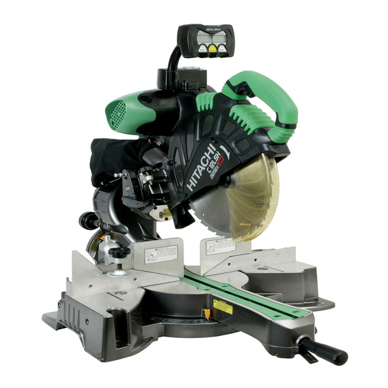
Page 4: Name Of Parts
NAME OF PARTS Digital display Motor Nameplate Gear case (only C12LSH) Motor head Dust bag Handle Locking pin Spindle cover Hinge Holder (A) Rotation Clamp lever direction Laser marker Lower guard Knob (B) Indicator (For right bevel scale) Saw blade... -
Page 5: Specifications
Left (Bevel) 0° – 45°, Left (Miter) 0° – 45°, Right (Miter) 0° – 31° Right (Bevel) 0° – 45°, Right (Miter) 0° – 45°, Left (Miter) 0° – 31° Net weight C12LSH 30 kg C12RSH 29 kg Cord 2 Conductor type cable 1.8 m... -
Page 6: Preparation Before Operation
Adjust the holder until its bottom surface contacts the NOTE work bench surface. Accessories are subject to change without any After adjustment, firmly tighten the 6 mm bolt. obligation on the part of the HITACHI. APPLICATIONS Wood and aluminum sash. 6 mm Bolt Holder... -
Page 7: Before Using
2. Releasing the locking pin When the power tool is prepared for shipping, its main parts are secured by a locking pin. Move the handle slightly so that the locking pin can be disengaged. Handle Lower guard Fig. 7 Locking pin WARNING NEVER OPERATE THE POWER TOOL if the lower Pull... -
Page 8: Before Cutting
Table inserts are installed on the turntable. When BEFORE CUTTING shipping the tool from the factory, the table inserts are so fixed that the saw blade does not contact them. 1. Cutting a groove on the guard The burr of the bottom surface of the workpiece is Holder (A) has a guard (see Fig. - Page 9 (1) Turn the 8 mm depth adjustment bolt, change the Turn Right bevel angle cutting Left bevel angle height where the bolt head and the hinge contacts, Direct angle cutting cutting and adjust the lower limit position of the saw blade. NOTE Confirm that the saw blade is adjusted so that it will not cut into the turntable.
- Page 10 9. Installing the holders ... (Optional accessory) (2) Miter cutting and compound cutting The holders help keep longer workpieces stable and (Miter cutting + bevel cutting) in place during the cutting operation. Upon lowering the motor section, the lower guard is (1) As indicated in Fig.
- Page 11 (1) Light up the laser marker and make a groove of about 5 mm deep on the workpiece that is about 20 mm in height and 150 mm in width. Hold the grooved workpiece by vise as it is and do not move it. For grooving work, refer to “13.Groove cutting procedures”...
- Page 12 • The laser marker will not light up if the digital display Fig. 25-b switch is turned off. (only on C12LSH) • Do not use the main unit near equipment that generates electrical noise such as generators.
-
Page 13: Practical Applications
WARNING PRACTICAL APPLICATIONS Always firmly clamp or vise to secure the workpiece to the fence; otherwise the workpiece might be thrust WARNING from the table and cause bodily harm. To avoid personal injury, never remove or place a CAUTION workpiece on the table while the tool is being Always confirm that the motor head (see Fig. - Page 14 Continued cutting operation can result in overload of 1 Pull forward the motor. Touch the motor and if it's hot, stop your 3 Push rearward cutting operation once and rest for 10 minutes or so, to cut Handle and then restart your cutting operation. Do not operate the head section or lift up the main unit while grasping the digital display (Fig.
- Page 15 Loosen Tighten Clamp Lever Clamp lever Pull Knob (B) Holder (A) Indicator Bevel scale Set pin (A) (for right bevel scale) Fig. 35 Fig. 33 (1) Grip the handle on the motor head and position it at the bevel angle you need. Temporarily tighten the WARNING clamp lever.
- Page 16 (2) Re-tighten the side handle to secure the turntable in 11. Compound cutting procedures the desired position. Compound cutting can be performed by following the (3) The miter scale (Fig. 37) indicates both the cutting angle instructions in 7 and 10 above. For maximum on the angle scale and the gradient on the grade scale.
- Page 17 Head To process crown To process crown molding at positions molding at positions Type of 1 and 4 in Fig. 41. 2 and 3 in Fig. 41. Crown Molding Miter Angle Bevel Angle Miter Angle Bevel Angle Setting Setting Setting Setting 45°...
- Page 18 • Crown molding Stopper (L) Head • Crown molding Stopper (R) Crown molding Bevel angle scale stopper (R) Crown molding vise ass’y (optional accessories) (optional accessories) 6mm knob bolt 6mm knob bolt Fence (A) Miter angle scale Turntable Base Crown molding stopper (L) Fig.
- Page 19 Position crown molding with its WALL CONTACT EDGE 14. Cutting easily-deformed materials, such as aluminum against the guide fence and its CEILING CONTACT EDGE sash against the crown molding Stoppers as shown in Fig. 50-b. Materials such as aluminum sash can easily deform Adjust the crown molding Stoppers according to the size when tightened too much in a vise assembly.
-
Page 20: Saw Blade Mounting And Dismounting
CAUTION Empty the dust bag frequently to prevent the duct and Washer (B) the lower guard from becoming clogged. Tighten 10 mm bolt Sawdust will accumulate more quickly than normal during bevel cutting. Loosen SAW BLADE MOUNTING AND DISMOUNTING WARNING To prevent an accident or personal injury, always turn Fig. -
Page 21: Maintenance And Inspection
(A) and pulley (B). Then turning the pulley (A) and on this tool should ONLY be performed by a Hitachi pulley (B), connect all 13 teeth of the belt to the pulleys. Authorized Service Center. -
Page 22: Service And Repairs
To assure that only authorized replacement parts will be used and that the double insulation system will be protected, all service (other than routine mainte- nance) must be performed by an AUTHORIZED HITACHI POWER TOOL REPAIR CENTER ONLY. NOTE Specifications are subject to change without any obligation on the part of HITACHI. - Page 32 Hitachi Koki Co., Ltd. Code No. C99141312 Printed in China...