
Related Manuals for Sailor A1


Summary of Contents for Sailor A1
- Page 1 SAILOR A1 Basic VHF Operating Instructions Distress Call, see page ii. Contents, see page 1.
-
Page 2: Distress Call
DISTRESS Call 1. If off or UNIT OFF: press ON/OFF. 2. Hook off the handset. 3. To enter VHF mode on CH 16 press 1 10 03 Press Pressing PTT, say: “MAYDAY” “This is” - the 9-digit identity and the call sign or other identification of the ship, - The ship’s position, - The nature of distress and... -
Page 3: Abbreviations Used In This Manual
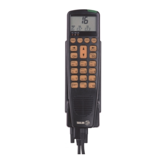
Handset What is What? Abbreviations Used in this Manual ADDR Address ATIS Automatic Transmitter Identification System Channel Mode used when sailing on European rivers 1. Display 9. FUNC key (details on p. 7) 2. Indicator lamps 10. ON/OFF button Control Unit 11. -
Page 4: Introduction
Doc. No.: B4900GB0 Issue: H/0139 The SAILOR A1 Basic and A1 DSC are part of the new SAILOR System 4000. This is a full range of maritime communication equipment developed to increase safety and ease communication for all kinds of vessels: leisure boats, fishing vessels, cargo ships, and cruise liners. -
Page 5: Table Of Contents
Contents DISTRESS Call ..............ii Handset ................iii What is What? ..............iii Abbreviations Used in this Manual ........iii Introduction ................. iv About this Manual .............. iv Telephony Display ............... 2 Handset Main Function Keys ..........2 Basic Operation ..............3 Switching ON/OFF ............ -
Page 6: Telephony Display
Telephony Display Handset Main Function Keys Normal display ON/OFF key. Turns the handset on or off. “16” key. Selects TELEPHONY mode and channel 16. Function menu. Enters the function menu to set up the handset and system. If function menu is active it enters VHF telephony mode. -
Page 7: Basic Operation
Listening for Telephony Calls Basic Operation According to international rules, all ships shall monitor channel 16 constantly: Switching ON/OFF 1. Select channel 16 by pressing: 1 10 03 2. Set the squelch level by means of the buttons To switch on the handset unit, push the ON/OFF button on the handset. -
Page 8: Receiving A Telephony Call
Receiving a Telephony Call Making a Telephony Call When a call comes in, and your call name is heard in the loud- In telephony mode: speaker: 1. Hook off the handset. Press 1 08 02 2. Press the PTT key on the handset. 1. -
Page 9: Channel Control
Channel Control Setting the VHF channel can be done in three ways by means of the The next channel function is active until the key numeric input keys (sequentially) or by means of the function “next is released again, toggling through the channel up/down”, or by using the quick select key “16”: channels as long as pushed. -
Page 10: Setting The Volume Level
Setting the Volume Level Setting Transmitter Power Level Setting the volume level can be done both for the speaker and the The handset can control the transmitter power level, which can be earpiece individually. (The setting can be 0-15). set to either 1W or 25W. The volume level of the speaker can be controlled when handset is on hook, or the speaker is set to be active when handset is hooked Low power 1W is indicated by the indicator lamp on the display. -
Page 11: Full Operation
Full Operation Full VHF Telephony Operation Setting Channel Mode 25W Transmitter Power Level NB! For US channels 13 and 67. Some VHF radios offer a choice between two sets of channels, If the VHF is programmed with the set of US called channel modes. -
Page 12: Setting Memory Scan Table
Setting Memory Scan Table Scanning of Channels The VHF 4000 system has eight independent sets of memory tables to save channels for making scanning sessions. Each memory table To start scanning: Pr - may contain all channels available in the system. To distinguish between the tables, each table has a number (0-7) Press and to each number can be attached a name of maximum seven... - Page 13 If scanning is in progress and a signal is detected on eg. channel 6, To delete a channel from a scan table: the display changes to show the selected channel number and Select channel number (shown on the display), and then volume level.
-
Page 14: Dual Watch
To view contents of channels in a scan table: Dual Watch Viewing which channels a specific scan table contains, can be done The handset may perform a dual watch of channels, a priority in two ways: channel and the selected channel being monitored simultaneously. While the key is being pressed down, the display will step through the channels of the scan table selected. -
Page 15: Keyboard Lock
Keyboard Lock Intercom The handset has a keyboard lock, which locks some keys to avoid If your VHF system has more than one control unit, it is possible to unintentional channel changes during a telephony session. carry out an intercom between two control units. When the keyboard is locked the only functions that can be con- When the intercom feature is used the handset will perform as trolled are:... - Page 16 This indicates that a dial-up is in progress to the control unit with location number 2. The lower part of the display now toggles the message CALLING and the NAME of the called control unit. During the dialling time of 30 seconds it is possible to hook off the handset and speak into the microphone.
-
Page 17: Function Menu
Function Menu The function menu offers facilities to view and set up the functionality of the handset unit. It also offers facilities to view and change functionality of the VHF transceiver and of the DSC modem as well. To enter the function menu. To view or set any specific items in the function menu press the keys FUNC TELEPHONY... - Page 18 Example: To activate keyboard “beep” function for keyboard to beep every time a key is pressed. SELECT FUNC Edits item Y(es)/N(o) FUNC KB.BEEP Y Enters the function menu TELEPHONY When Y(es)... FUNC FUNC Selects the setting and reenters the function menu GENERAL TELEPHONY Pushed twice, finds the general entry...
-
Page 19: Function Menu Item Description
Function Menu Item Description Path: Data: Description: Light intensity of each indicator lamp dimmer GENERAL\ILLUMIN\INDICATOR\LEVL_0-3 level. Light intensity of each display backlight GENERAL\ILLUMIN\DISPLAY\DB_L_0-3 dimmer level. GENERAL\ILLUMIN\DIMMER\D_LEVL Dimmer level when handset is turned on. Dimmer level start direction (see diagram on GENERAL\ILLUMIN\DIMMER\D_LEVL\DIMDIR next page). - Page 20 The dimmer start direction can be set up in three different ways: Start direction 0: Start direction 1: Start direction 2:...
-
Page 21: Function Menu Tree
FUNCtion Menu Tree Telephony Scanner Mem-no X Name XXX Pr-ch XX Pr_sc X Squelch Mode X Atis no XXXXXXXXX General Illumin Indicator Levl_0 X Levl_1 X Levl_2 X Levl_3 X Display Levl_0 X Levl_1 X Levl_2 X Levl_3 X Dimmer D_levl X D_dir X Keyboard... -
Page 22: Vhf System Description
When a control unit is master of the system, VHF System Description the other control units, if in VHF mode, show the following display to To the VHF system can be connected up to 7 control units. Each indicate that the transceiver is in use by another control unit: control unit has a unique location (1-7). -
Page 23: International Channels
International Channels &KDQQHOV 6,03/(; '83/(; &KDQQHOV 6,03/(; '83/(; ,QWHUVKLS 3RUW 3RUW 3XEOLF ,QWHUVKLS 3RUW 3RUW 3XEOLF 156,050 160,650 156,025 160,625 156,100 160,700 156,075 160,675 156,150 160,750 156,125 160,725 156,200 160,800 156,175 160,775 156,250 160,850 156,225 160,825 156,300 156,300 156,275 160,875 156,350 160,950 156,325 160,925 156,400 156,400... -
Page 24: Us Channels
US Channels &KDQQHOV 6,03/(; '83/(; &KDQQHOV 6,03/(; '83/(; &KDQQHOV 156,050 156,050 162,550 156,075 156,075 162,400 156,150 156,150 162,475 156,175 156,175 162,425 156,250 156,250 156,225 156,225 162,450 156,300 156,300 156,275 156,275 162,500 156,350 156,350 156,325 156,325 162,525 156,400 156,400 156,375 156,375 161,650 156,450 156,450 156,425 156,425... -
Page 25: Bi Channels
BI Channels &KDQQHOV 6,03/(; '83/(; &KDQQHOV 6,03/(; '83/(; ,QWHUVKLS 3RUW 3RUW 3XEOLF ,QWHUVKLS 3RUW 3RUW 3XEOLF 156,050 160,650 156,025 160,625 156,100 160,700 156,075 160,675 156,150 160,750 156,125 160,725 156,200 160,800 156,175 160,775 156,250 160,850 156,225 160,825 156,300 156,300 156,275 160,875 156,350 160,950 156,325 160,925 156,400 156,400...