Table of Contents
VENTILCONVETTORE
CON TERMOSTATO ELETTRONICO
FAN COIL
FOR UNIVERSAL INSTALLATION
WITH ELECTRONIC THERMOSTAT
VENTILO-CONVECTEUR
MUNI DE THERMOSTAT ÉLECTRONIQUE
GEBLÄSEKONVEKTOR
MIT ELEKTRONISCHEM THERMOSTAT
FAN COIL
PARA INSTALACIÓN UNIVERSAL
CON TERMOSTATO ELECTRÓNICO
Omnia UL N
Omnia UL 11 N
Omnia UL 16 N
Omnia UL 26 N
Omnia UL 36 N
Sostituisce il • Replace • Remplace le n° • Ersetzt • Sustituye a: 4528500_01 / 0809
M A N U A L E
D ' U S O
U S E
A N D
I N S T A L L A T I O N
MANUEL D'UTILISATION ET D'INSTALLATION
BEDIENUNGS- UND INSTALLATIONSANLEITUNG
MANUAL DE INSTRUCCIONES E INSTALACIÓN
PER INSTALLAZIONE UNIVERSALE
POUR INSTALLATION UNIVERSELLE
FÜR UNIVERSELLEN EINBAU
IULNLJ 1002 - 6976415_00
E
I N S T A L L A Z I O N E
M A N U A L
Table of Contents

Related Manuals for AERMEC Omnia UL 11 N


Summary of Contents for AERMEC Omnia UL 11 N
- Page 1 MIT ELEKTRONISCHEM THERMOSTAT FAN COIL PARA INSTALACIÓN UNIVERSAL CON TERMOSTATO ELECTRÓNICO Omnia UL N Omnia UL 11 N Omnia UL 16 N Omnia UL 26 N Omnia UL 36 N IULNLJ 1002 - 6976415_00 Sostituisce il • Replace • Remplace le n° • Ersetzt • Sustituye a: 4528500_01 / 0809...
- Page 2 Alle in diesem Handbuch enthaltenen Informationen auf- sich für die Garantiearbeiten als erforderlich erweisen sollten. merksam und vollständig lesen. Insbesondere auf die Die AERMEC S.p.A. übernimmt keine Haftung für Schäden aus Benutzungsanweisungen mit den Hinweisen "VORSICHT" oder dem unsachgemäßen Gebrauch des Gerätes und der teilweisen "ACHTUNG"...
- Page 3 INDICE DICHIARAZIONE DI CONFORMITÀ DECLARATION OF CONFORMITY DÉCLARATION DE CONFORMITÉ KONFORMITÄTSERKLÄRUNG DECLARACIÓN DE CONFORMIDAD Trasporto • Simboli di sicurezza Transport • Safety symbols Transport • Symboles de sécurité Transport • Sicherheitssymbole Transporte • Símbolos de seguridad Italiano English Français Deutsche Español Dimensioni Dimensions...
- Page 4 Il est interdit de faire fonctionner l'appareil avec des accessoires qui ne Falls das Gerät mit Zubehörteilen ausgerüstet wird, die nicht von sont pas fournis de Aermec. Aermec geliefert werden, ist dessen Inbetriebnahme solange untersagt. DECLARACIÓN DE CONFORMIDAD Los que suscriben la presente declaran bajo la propia y exclusiva responsabilidad que el conjunto en objeto, defi...
- Page 5 TRASPORTO • CARRIAGE • TRANSPORT • TRANSPORT • TRANSPORTE NON bagnare • Do NOT wet NON calpestare • Do NOT trample CRAINT l’humidité • Vor Nässe schützen NE PAS marcher sur cet emballage • Nicht betreten NO mojar NO pisar Sovrapponibilità: controllare sull’imballo la sovrapponibilità...
-
Page 6: Table Of Contents
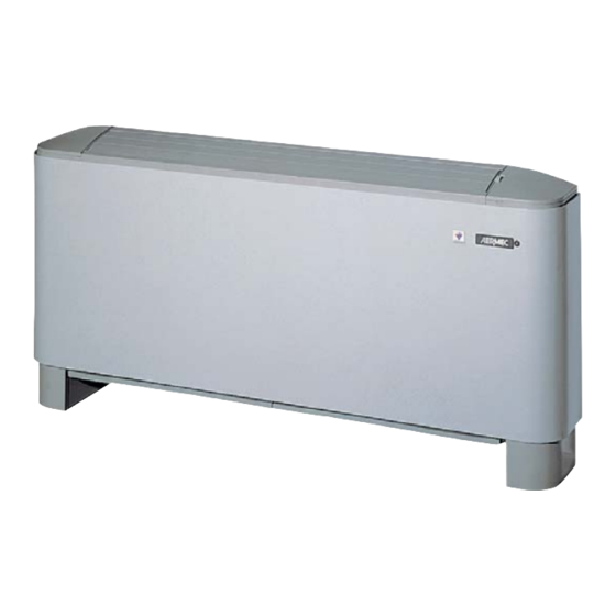
Congratulations on your purchase of the Aermec OMNIA UL_N fan coil. Made with materials of superior quality in strict compliance with safety regulations, "OMNIA UL_N" is easy to use and will have a long life. CONTENTS Important information • Package Maintenance •... -
Page 7: Important Information • Package
IMPORTANT INFORMATION you follow this rule, the energy (otherwise dust in the air could WARNING: OMNIA fan coils of the electrostatic charges can- soil the coil surface area). are designed for indoor use. not reach or damage the sensitive WHAT IS NORMAL parts. -
Page 8: Troubleshooting
Extraordinary maintenance can - cleaning the electrostatically pre- the fan fins, the basin and all only be performed by Aermec charged filter, every two weeks the parts in contact with the After-Sales Services or by people or weekly if the installation is in a treated air. -
Page 9: Control Panel Functions
CONTROL PANEL FUNCTIONS Ventilation is only allowed with the fin open; it must be manually opened. The closure of the fin causes venti- lation to switch off. To access the control panel, lift the protection flap. Closing the master fan coil fin, the electronic thermostat card and the other fan coils in the network will carry on working. -
Page 10: Use
Starting - To start up the fan coil, turn the knob and choose a ventilation speed. - To switch off the fan coil, turn the knob to the position. The fan coil is switched off. In the OFF condition, the thermostat carries on working. If the room temperature falls below 7°C, and the system conditions allow it, the thermostat will activate ventilation (anti-freeze function). - Page 11 INDICATOR LIGHTS FOR THE USER (STANDARD CONFIGURATION) LED D indicates a ventilation request: YELLOW - (ON) The ambient conditions require the use of the fan (when the speed selector is on AUTO, V1, V2, V3) - (OFF) The ambient conditions do not require the use of the fan, or the selector is in the OFF (standby) position, or the fin is closed - (slow flashing) Operation mode managed by the centralised system.
-
Page 12: Operation
OPERATION The OMNIA UL_N fan coil concentrates ensure thorough cleaning of the unit The settings made on the control panel hi-tech and highly functional features (by specifically trained personnel), can be transmitted (without additional that make it the ideal means of climate essential for installations in venues sub- interfaces) to a network with up to control in every room. - Page 13 - Modulated output thermostat, with positioned downstream or upstream tronic card can automatically detect the the selector on AUTO. The fan makes from the shutoff valve, so also the dip- problem and enable an emergency pro- cycles, alternating the speeds according switches on the card must be set.
-
Page 14: Description Of The Unit
DESCRIPTION OF THE UNIT AIM OF THE UNIT The fan coil is a room air treatment terminal unit for both winter and summer operation. Omnia UL_N version A fan coil with cabinet, for universal installation and fitted with a multifunction electronic thermostat. It can be installed as an autonomous unit or within a network: it can, in fact, manage a network of a further 5 fan coils*. - Page 15 C O R R E C T I O N F A C T O R S W H E N O P E R A T I N G U S I N G G L Y C O L W A T E R Key: Pressure drops...
-
Page 16: Main Components
MAIN COMPONENTS 1 Control panel (UL N) 7 Fan motor 2 Electronic card 8 Fan 3 Cabinet 9 Basin 4 Feet (accessory ZU) 10 Heat exchange coil 5 Load-bearing structure 11 Head with adjustable fins 6 Air filter OMNIA UL_N DESCRIPTION OF COMPONENTS CON TR OL PA NEL pipes. - Page 17 ELECTROSTATICALLY PRECHARGED AIR FILTER = Aermec UL range filter = Standard filter for fan coils 0 , 3 0 , 5 0 , 7 1 , 0 2 , 0 Particle diameter [µm] INSTALLATION insulation strength. with the treated air can be deposited...
- Page 18 UNIT INSTALLATION - Loosen the screws to remove the housing. supplied) with suitable characteristics - Make all the connections. - With wall-mounted units, keep a for the specific type of wall. - Reassemble the casing. minimum clearance of 80mm from - Apply any accessories.
-
Page 19: Water Connections
CONNECTIONS The water, condensate discharge and electrical circuit ducts must be provided for. WATER CONNECTIONS - Make the water connections. To help The position and diameter of the accessory), to prevent dripping during the bleeding of air from the coil, you water connections are shown in the the cooling function. - Page 20 CONNECTIONS TO THE ELECTRONIC CARD Connections key: L - N = Power supply SP = Not present MS = Microswitch 230V AC - 50Hz Edge-type connector SW = Water probe Screw clamps Analogue input Control panel - TTL = Local serial TTL Minimum cable section = 0.5mm Faston-type connector Removable-type connector...
- Page 21 1 2 3 4 5 6 7 8 1 2 3 4 5 6 7 8 INSTALLING THE ELECTROSTATICALLY PRECHARGED AIR FILTER • • (available as a spare part from Aermec Installation Characteristics After Sales centres). - Remove the suction filter frame from Class 2 (UL 900).
- Page 22 DIMENSIONI • DIMENSIONS • ABMESSUNGEN • DIMENSIONES [mm] 5 0 m 5 0 m UL 11N Larghezza • Width • Largeur • Breite • Longitud 1200 Altezza • Height • Hauteur • Höhe • Altura Profondità • Depth • Profondeur • Tiefe • Profundidad Altezza zoccoli •...
- Page 23 DIMENSIONI • DIMENSIONS • ABMESSUNGEN • DIMENSIONES [mm] 1 Testata con alette orientabili 2 Mobile di copertura 3 Struttura portante 4 Zoccolo UL 5 Spazio per i collegamenti 1 Head with adjustable fins 2 Cabinet 3 Load-bearing structure 4 Foot UL 5 Space for connections 1 Tête avec ailettes orientables 2 Carosserie de protection...
- Page 24 SCHEMI ELETTRICI • WIRING DIAGRAMS • SCHEMAS ELECTRIQUES • ELEKTRISCHE SCHALTPLÄNE • ESQUEMAS ELECTRICOS LEGENDA • KEY • LEGENDE • LEGENDE • LEYENDA = Interruttore generale • Master switch • Interrupteur général • Hauptschalter • Interruptor general = Morsettiera • Control board • Bornier • Klemmleiste • Caja de conexiones = Microinterruttore •...
-
Page 25: Wiring Diagrams
SCHEMI ELETTRICI • WIRING DIAGRAMS • SCHEMAS ELECTRIQUES • ELEKTRISCHE SCHALTPLÄNE • ESQUEMAS ELECTRICOS LEGENDA • KEY • LEGENDE • LEGENDE • LEYENDA = Arancio = Orange = orange = Orange = Naranja = Bianco = White = blanc = Weiß = Blanco = Blu = Blue... - Page 26 AERMEC S.p.A. si riserva la facoltà di apportare in qualsiasi momento tutte le modifiche ritenute necessarie per il miglioramento del prodotto. Les données mentionnées dans ce manuel ne constituent aucun engagement de notre part. Aermec S.p.A. se réserve le droit de modifier à tous moments les données considérées nécessaires à...