Table of Contents
REVISED VERSION
This manual is to amend the following content provided in the Service Manual (SC No. 0015E)
issued on Dec 2005 :
(1) "WIRING DIAGRAM" on page 12
(2) "PCB DIAGRAMS" on page 19, 21-22 & 24
(3) "TROUBLESHOOTING" on page 29-39
(4) "REPLACEMENT PART LIST" on page 40-50
Please ignore these pages and replace them with the following pages respectively.
SPECIFICATIONS AND PARTS ARE SUBJECT TO CHANGE FOR IMPROVEMENT
Jun 2006
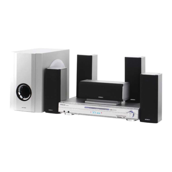
DVD Home Theatre System
Digital Media Systems Group, Hitachi Asia Ltd.
HTD-K210
REVISE THE SERVICE MANUAL
(SC No. 0015E) ISSUED ON DEC
2005
-1
Table of Contents

Related Manuals for Hitachi HTD-K210


Summary of Contents for Hitachi HTD-K210
- Page 1 (4) “REPLACEMENT PART LIST” on page 40-50 Please ignore these pages and replace them with the following pages respectively. SPECIFICATIONS AND PARTS ARE SUBJECT TO CHANGE FOR IMPROVEMENT DVD Home Theatre System Jun 2006 Digital Media Systems Group, Hitachi Asia Ltd.
- Page 2 WIRING DIAGRAM (To replace Pg 12 of SC No. 0015E) YZEA9288 YZEA9464 FUNCTION BUTTON BOARD 1 YZEA9287 YZEA9286 FUNCTION BUTTON BOARD 3 YZEA9285 YZES30970 TRAY IN FUNCTION BUTTON BOARD 2 TRAY OUT DATA LOAD+ LOAD- YZES30969 POWER SW LIMIT YZES3772 YZES30967 HVCC SD/USB BOARD...
- Page 3 SCHEMATIC DIAGRAMS (To replace Pg 19 of SC No. 0015E) DVA2630 FUNCTION BUTTON CIRCUIT DIAGRAM...
- Page 4 (To replace Pg 21 of SC No. 0015E) POWER CIRCUIT DIAGRAM (REVISED)
- Page 5 (To replace Pg 22 of SC No. 0015E) AMP CIRCUIT DIAGRAM (REVISED)
- Page 6 (To replace Pg 24 of SC No. 0015E) DECODER PCB CIRCUIT DIAGRAM 1 (REVISED)
- Page 7 TROUBLESHOOTING (To replace Pg 29-39 of SC No. 0015E) SYMPTOM: POWER CIRCUIT ABNORMAL (REVISED) Start Secure the Is the No defect, return connection of Set OK? AC power of set to customer power cord. C333 220V? Replace F3011. Is the Replace L301.
- Page 8 (To replace Pg 29-39 of SC No. 0015E) SYMPTOM: OUTPUT DISPLAY ABNORMAL (REVISED) Start Is the voltage at F+ & F- of Replace VF1. VF1 normal? Is the voltage at pin 34 of Replace PT6311. PT6311 -24V? Is the connection Secure the connection of Function Button Function Button...
- Page 9 (To replace Pg 29-39 of SC No. 0015E) SYMPTOM: LOAD DISC ABNORMAL (REVISED) Start Check the Replace Loading Pick-up lens light up dimly optical pick-up Assy lens Pick-up lens do not light up at all Check the connectors of the Loading Assy &...
- Page 10 (To replace Pg 29-39 of SC No. 0015E) SYMPTOM: AUDIO CIRCUIT ABNORMAL (REVISED) Start Is the relay Replace S1, S2 S1,S2 & S3 short or S3 at standby? Is the Refer to Symptom voltage of XP3 pin 2,5 +/-19V “Power Circuit Abnormal”...
- Page 11 REPLACEMENT PART LIST (To replace Pg 40-50 of SC No. 0015E) The following service parts list are available for purchase. Serviceman may quote the components shown in this page for servicing purposes. PRODUCT SAFETY NOTE : Components marked with a have special characteristics important to safety.
- Page 12 REPLACEMENT PART LIST (To replace Pg 40-50 of SC No. 0015E) The following service parts list are available for purchase. Serviceman may quote the components shown in this page for servicing purposes. PRODUCT SAFETY NOTE : Components marked with a have special characteristics important to safety.
- Page 13 PART NAME Q'TY HTD-K210 × × × × × × × × YZES7713 DVA2630 FUNCTION BUTTON ASS'Y YZES14154D HTD-K210 OWNER MANUAL (ENGLISH) YZES14154E HTD-K210 OWNER MANUAL (CHINESE) YZES14154F HTD-K210 OWNER MANUAL (RUSSIA) YZES14154G HTD-K210 OWNER MANUAL (ARABIA) YZEA7755 CCT5902-0701C SOCKET (GERMAN)
- Page 14 PART LIST (FOR REFERENCE ONLY) (To replace Pg 40-50 of SC No. 0015E) The components shown in the remaining pages served as a reference only. It is not meant for ordering of components for servicing purposes. Do not quote any components from these lists. REF No.
- Page 15 PART LIST (FOR REFERENCE ONLY) (To replace Pg 40-50 of SC No. 0015E) The components shown in the remaining pages served as a reference only. It is not meant for ordering of components for servicing purposes. Do not quote any components from these lists. REF No.
- Page 16 PART LIST (FOR REFERENCE ONLY) (To replace Pg 40-50 of SC No. 0015E) The components shown in the remaining pages served as a reference only. It is not meant for ordering of components for servicing purposes. Do not quote any components from these lists. REF No.
- Page 17 PART LIST (FOR REFERENCE ONLY) (To replace Pg 40-50 of SC No. 0015E) The components shown in the remaining pages served as a reference only. It is not meant for ordering of components for servicing purposes. Do not quote any components from these lists. REF No.
- Page 18 PART LIST (FOR REFERENCE ONLY) (To replace Pg 40-50 of SC No. 0015E) The components shown in the remaining pages served as a reference only. It is not meant for ordering of components for servicing purposes. Do not quote any components from these lists. REF No.
- Page 19 PART LIST (FOR REFERENCE ONLY) (To replace Pg 40-50 of SC No. 0015E) The components shown in the remaining pages served as a reference only. It is not meant for ordering of components for servicing purposes. Do not quote any components from these lists. REF No.
- Page 20 No. 0015E-1 Copyright Digital Media Systems Group, (2006) All rights reserved...
-
Page 21: Table Of Contents
Be sure to read this manual before servicing. To assure safety from fire, electric shock, injury harmful radiation and materials, various measures are provided in this Hitachi DVD home theatre system. Be sure to read the cautionary items described in the manual to maintain safety before servicing. -
Page 22: Safety Notice
SAFETY NOTICE PRODUCT SAFETY SERVICING GUIDELINES FOR VIDEO PRODUCTS SUBJECT GRAPHIC SYMBOLS CAUTION: DO NOT ATTEMPT TO MODIFY THIS PRODUCT IN ANY WAY AND N E V E R P E R F O R M C U S T O M I Z E D I N S T A L L AT I O N S W I T H O U T THE LIGHTNING FLASH WITH APROWHEAD SYMBOL. - Page 23 SERVICING PRECAUTIONS CAUTION : Before servicing the DVD covered by this Electrostatically Sensitive (ES) Devices service data and its supplements and ADDENDUMS, read Some semiconductor (solid state) devices can be damaged and follow the SAFETY PRECAUTIONS NOTE : if easily by static electricity. Such components commonly are unforeseen circumstances create conflict between the called Electrostatically Sensitive (ES) Devices.
-
Page 24: Product Specifications
PRODUCT SPECIFICATIONS DVD Player Pickup Semiconductor Laser, wavelength 650nm Signal System PAL/AUTO/NTSC Video Signal Horizontal Resolution 480 Lines (DVD) Video Signal-to-noise Ratio 50dB (DVD) Audio Frequency Response (at 2 CH Stereo Mode) DVD (PCM): 180Hz ~ 20kHz (+/-1.0dB) CD: 180Hz ~ 20kHz (+/-1.0dB) Audio Signal-to-noise Ratio 85dB Total harmonic Distortion... -
Page 25: Functional Overview
FUNCTION TUNING MEMORY MENU TITLE PLAY PAUSE STOP PREV NEXT VOLUME HITACHI HTD-K210 OPEN/CLOSE DOWN STANDBY CARD SLOT USB MEMORY MIC1 MIC2 MIC LEVEL ECHO 1. POWER ( ON/STANDBY) 11. VOLUME UP/DOWN Press to turn the unit on or standby. -
Page 26: Rear Panel
Front Panel Display MEMORY PROG STEREO MONO 1. DVD 7. ANGLE 13. SECOND Indicator Indicator Indicator 2. CD 8. DOLBY DIGITAL 14. MINUTE Indicator Indicator Indicator 3. TITLE 9. PROGRAM 15. TITLE/CHAPTER/TRACK Indicator Indicator Indicator 4. CHAPTER/TRACK 10. MONO 16. PAUSE Indicator Indicator Indicator... -
Page 27: Remote Control
Press to display the titlemenu while playing a DVD disc. 22. PAUSE ( Press to pause a playback. RETURN 23. STOP ( Press to stop a playback. HITACHI 24. REPEAT HTD-RM210 Press to repeat a disc/title/chapter/track playback. 25. FUNCTION Press to select DVD, TUNER or AUX mode. -
Page 28: Connections
CONNECTIONS Switch off all power supplies to the equipments before connection. The unit has many kinds of output modes like AV output, S-Video output, Component Video/Progressive Scan output and digital signal output (Optical and Coaxial). Connecting to a TV FM Antenna To S-Video Input To Video Input VIDEO... -
Page 29: Connecting To An Amplifier
Connecting to an Amplifier To Video Input VIDEO FM 75 COAXIAL OPTICAL SUBWOOFER FRONT SURROUND CENTER COMPONENT VIDEO / S-VIDEO AUDIO OUT AUX IN PROGRESSIVE SCAN OUT (5.1 CHANNEL) Amplifier To Audio Input NOTE: There will be no sound output from the output terminal when a Digital Theater System (DTS) disc is played. Connecting to an Amplifier with Digital Signal Input To Video Input VIDEO... - Page 30 Connecting to an Amplifier with 5.1 channel Surround Sound To Video Input To S-Video Input VIDEO FM 75 COAXIAL OPTICAL SUBWOOFER FRONT SURROUND CENTER COMPONENT VIDEO / S-VIDEO AUDIO OUT AUX IN PROGRESSIVE SCAN OUT To Video Input (5.1 CHANNEL) Amplifier To Subwoofer Input To Surround Speaker R/L Input...
- Page 31 Connecting to Speakers Center Subwoofer Front Front Left Right REAR FRONT SUBWOOFER CENTER (IMPEDANCE 4 ) (IMPEDANCE 6 ) SPEAKER SYSTEMS Rear Rear Left Right Connecting to Speaker Terminals 1. Push the lever. 2. Insert the cord. 3. Return the lever.
-
Page 32: Wiring Diagram
WIRING DIAGRAM FUNCTION BUTTON BOARD 1 FUNCTION BUTTON BOARD 3 FUNCTION BUTTON BOARD 2 TRAY IN TRAY OUT DATA LOAD+ LOAD- POWER SW LIMIT LD-DVD AVCC (DVD SD/USB BOARD HVCC MECHANISM USB- LD-CD KHL-310A) USB+ VR DVD VR CD SD-CLK L-VCC CD/DVD MIC BOARD... -
Page 33: Pcb Diagrams
PCB DIAGRAMS FUNCTION BUTTON BOARD DIAGRAM 1 FUNCTION BUTTON BOARD DIAGRAM 2 FUNCTION BUTTON BOARD DIAGRAM 3 FUNCTION BUTTON BOARD DIAGRAM 4... - Page 34 POWER BOARD DIAGRAM AMP BOARD DIAGRAM...
- Page 35 MIC BOARD DIAGRAM 2630 USB BOARD DIAGRAM...
- Page 36 DECODER BOARD DIAGRAM (TOP)
- Page 37 DECODERBOARD DIAGRAM (BOTTOM)
-
Page 38: Block Diagram
BLOCK DIAGRAM... -
Page 39: Schematic Diagrams
SCHEMATIC DIAGRAMS FUNCTION BUTTON CIRCUIT DIAGRAM... - Page 40 MIC CIRCUIT DIAGRAM...
- Page 41 POWER CIRCUIT DIAGRAM...
- Page 42 AMP CIRCUIT DIAGRAM...
- Page 43 SD/USB CIRCUIT DIAGRAM...
- Page 44 DECODER PCB CIRCUIT DIAGRAM 1...
- Page 45 DV33A CON1 +P12V +12V -P12V -12V AVCC RFV33 AV33 Alive LED CE12 CB11 CE15 +P12V +P12V 0.1uF 10uF/25v A 0.1uF 47uF/16v 0.1uF 0.1uF LED1 10uF/25v A 47uF/16v -P12V -P12V LED2 LED DIP2.54 LED DIP2.54 6x1 W/HOUSING DIP6/W/H/P2.54 AV33 DV33A URST# URST# CE10 DV33A...
- Page 46 DECODER PCB CIRCUIT DIAGRAM 3...
- Page 47 R108 +12V +12V 220pF AVDD5 DVDD3 AVDD5 -12V -12V -12V R110 AVCC DV33 ASDAT[0..2] 5.1k U13A R111 ASDAT[0..2] R109 LMAIN1 CB53 ACLK L CH CE36 ACLK ABCK CB48 CB52 10uF/25v A CB47 CE35 0.1uF ABCK ALRCK 0.1uF 100uF/16v R112 ALRCK R113 A_MUTE 2200pF...
- Page 48 DECODER PCB CIRCUIT DIAGRAM 5 DQ16 DQ17 DQ18 DQ19 DQ20 DQ21 DQ22 DQ23 DQ24 DQ25 MA10 DQ10 MA10 DQ26 MA10 DQ10 DQ10 DQ10 DBA0 DQ11 A10/AP DQ10 DBA0 DQ27 MA11 DQ11 BA/A11 DQ11 BA/A11 DQ11 DQ12 DQ11 DQ28 DBA0 DQ12 DQ12 DQ12 SDCLK...
-
Page 49: Troubleshooting
TROUBLESHOOTING GUIDES Connection of the unit is correct Setting of the unit is correct Is power normal? Refer to power guide Is fluoresce display correct? Refer to display guide Is open/close normal? Refer to open/close guide Can disc be read? Refer to read disc guide Is video normal? Refer to video guide... - Page 50 Power Circuit abnormal Scart F301 is open. XP301 is open. Is C333 AC 220V? Power cord isn’t inserted firmly or power cord is open. Check commute circuit. Is C305 DC 310V? Check L301. Is the voltage between 4,6 pin of N301 13V? Replace N301.
- Page 51 Display abnormal Scart Check if voltage of screen F1 and F2 is normal. Check if voltage of 34 pin of PT6311 is -24V. Does the screen appear? Check grounded negative voltage of screen F1 and F2. Replace PT6311. Check if connection cord between screen and decoder ass’y is broken.
- Page 52 Open/close abnormal Scart Is"open"showed on the screen? Is there voltage difference in L23 UNLOAD pin and LOAD pin? Check if RMC pin of XS9 have waveform. Does XS 9 power have voltage? Does drive motor have voltage? Replace key ass’y. Replace connection cord.
- Page 53 Read disc abnormal Disc in Fouse on? Refer to fouse guide. Is laser normal? refer to laser guide. Does the disc turn? Refer to fouse guide. Can TOC be read? Refer to TOC guide. Normal...
- Page 54 Video abnormal Scart No picture,no sound. Replace decoder ass’y. Check jack of output board or replace No picture,have sound. decoder ass’y. Have picture,no color or lolor Check decoder ass’y and replace G1(27MHz). disappeared during playback. Have picture,but picture Check decoder ass’y and replace G1(27MHz). disappearedduring playback.
- Page 55 Audio abnormal Have picture,no sound Check if voltage of R,L pin or Check STK402-920 and peripheral components. STK402-920 is normal? Is N1 signal output normal? Check N1 and peripheral components. Is signal of main board XS7 normal? Replace main board. Normal...
- Page 56 Focus abnormal No focus Does normal voltage at FCS+ Check connection cord. and FCS- of XS2? Replace pickup. Check connection between 14,7 pin of Does normal voltage at 14,7 BA5954 and FCS+,FCS- of XS2. pin of BA5954? Check if G1 normal operation. Check BA5954 and peripheral components.
- Page 57 Laser abnormal No laser Check connection between pickup Is LD pin of XS2(19,23) 4.5V? and decoder ass’y. Replace pickup. Check connection between 22,23 pin of Does voltage at 22,23 pin of D17? D1389 and LD pin of XS2. Check D1389 and peripheral components. Does noraml voltage at 24,46,52,65,69, 73,80,97,108,122,127,141,152,155,167, Check D1389 and peripheral components.
- Page 58 Turn abnormal Disc doesn’t turn Check if voltge of SP+ of SP- of XS4 Check connection of mechanism. are different. Check if voltage of 11 and 12 pin of Check connections between BA5954 and XS4 D9 are different. Check BA5954 and peripheral components. Check connections between 36 pin of D1389 Check if voltage of 36 pin of D17 is noraml.
- Page 59 TOC abnormal TOC doesn’t read Limited switch is closed. Refer to laser guide. Is laser on? Check slide motor and connections Is FOK noraml to decoder ass’y check connections between 8-11 pin of D17 Does normal A.B.C.D signal and 5,6,9,10 pin of XS2. at 8-11 pin of D17? Check connections between XS2 and pickup.
- Page 60 REPLACEMENT PRAT LIST The following service parts list are available for purchase. Serviceman may quote the components shown in this page for servicing purposes. PRODUCT SAFETY NOTE : Components marked with a have special characteristics important to safety. The use of a substitute replacement part which does not have the same safety characteristics may create shock, fire or other hazards.
-
Page 61: Replacement Part List
PART NAME Q’TY HTD-K210(Singapore) YZE22112 DHC2630 DECODER ASS’Y YZE22137 DVA2630SD/USB ASS’Y YZEA7594 TFCF1U802A RECEIVER YZES06152 HTD-RM210 REMOTE YZES14154B HTD-K210 OWNER MANUAL YZES2586 HTD-K210 SPEAKER ASS’Y YZES2588 HTD-K210 SUBWOOFER SPEAKER YZES2672 VDE POWER CORD YZES2701 7# BATTERY YZES3021A RCA CORD AUDIO... - Page 62 PART NAME Q’TY HTD-K210(UAE) YZE22112 DHC2630 DECODER ASS’Y YZE22137 DVA2630SD/USB ASS’Y YZEA7594 TFCF1U802A RECEIVER YZES06152 HTD-RM210 REMOTE YZES14154B HTD-K210 OWNER MANUAL YZES2586 HTD-K210 SPEAKER ASS’Y YZES2588 HTD-K210 SUBWOOFER SPEAKER YZES2637 BS POWER CORD YZES2701 7# BATTERY YZES3021A RCA CORD AUDIO...
- Page 63 PART NAME Q’TY HTD-K210(Germany) YZE22112 DHC2630 DECODER ASS’Y YZE22137 DVA2630SD/USB ASS’Y YZEA7594 TFCF1U802A RECEIVER YZES06152 HTD-RM210 REMOTE YZES14154B HTD-K210 OWNER MANUAL YZES2586 HTD-K210 SPEAKER ASS’Y YZES2588 HTD-K210 SUBWOOFER SPEAKER YZES2672 VDE POWER CORD YZES2701 7# BATTERY YZES3021A RCA CORD AUDIO...
- Page 64 PART NAME Q’TY HTD-K210(Russia) YZE22112 DHC2630 DECODER ASS’Y YZE22137 DVA2630SD/USB ASS’Y YZEA7594 TFCF1U802A RECEIVER YZES06152 HTD-RM210 REMOTE YZES14154B HTD-K210 OWNER MANUAL YZES2586 HTD-K210 SPEAKER ASS’Y YZES2588 HTD-K210 SUBWOOFER SPEAKER YZES2672 VDE POWER CORD YZES2701 7# BATTERY YZES3021A RCA CORD AUDIO...
- Page 65 The components shown in the remaining pages served as a reference only. It is not meant for ordering of components for servicing purposes. Do not quote any components from these lists. REF No. PART No. PART NAME REF No. PART No. PART NAME DVA2630 FUNCTION BUTTON ASS’Y YZEA5004 1N4148...
- Page 66 The components shown in the remaining pages served as a reference only. It is not meant for ordering of components for servicing purposes. Do not quote any components from these lists. REF No. PART No. PART NAME REF No. PART No. PART NAME YZEG0728 RT13-0.167W-4.7K–5% YZEA3579 CD11CX-100uF-M-16V...
- Page 67 The components shown in the remaining pages served as a reference only. It is not meant for ordering of components for servicing purposes. Do not quote any components from these lists. REF No. PART No. PART NAME REF No. PART No. PART NAME R305 YZEG0735 RT13-0.167W-10K–5%...
- Page 68 The components shown in the remaining pages served as a reference only. It is not meant for ordering of components for servicing purposes. Do not quote any components from these lists. REF No. PART No. PART NAME REF No. PART No. PART NAME L306 YZEA1126B CZ6V2...
- Page 69 The components shown in the remaining pages served as a reference only. It is not meant for ordering of components for servicing purposes. Do not quote any components from these lists. REF No. PART No. PART NAME REF No. PART No. PART NAME YZEA2324 CT1-05B-471K-50V-Y5P YZEA3306 CT4D-2F4-0.22uF-63V-S...
- Page 70 The components shown in the remaining pages served as a reference only. It is not meant for ordering of components for servicing purposes. Do not quote any components from these lists. REF No. PART No. PART NAME REF No. PART No. PART NAME YZEA6514 9 PINS SOCKET YZEP20015 GRM39F104Z25PT...
- Page 71 HTD-K210 SC No. 0015E Copyright Digital Media Systems Group, (2005) All rights reserved...