Table of Contents
SERVICE MANUAL
SPECIFICATIONS
American TV standard
TV standard
VHF channels 2-13
Channel
coverage
UHF channels 14-69
Radio frequency range
FM 87.6-l 08 MHz
AM 530-l ,710 kHz
VHF/UHF/FM: telescopic antenna
A n t e n n a
AM: Built-in ferrite
picture measured diagonally
Picture tube
EXT ANT: minijack, 75 ohms
Input
EAR: minijack,
output
impedance
range
Full
Speaker
Power requirements 12 V DC
Battery life
See page 4 for "Power sources."
Power consumption 10.8 W
Approx. 176.2 x 177x 175.5 mm (w/h/d)
Dimensions
(7 x 7 x 7 inches)
Mass
Approx. 2.8 kg (6 lb 3 oz)
Supplied accessory
AC power adaptor (1)
Design and specifications are subject to change without
notice.
Note
Use only recommended AC power adaptor. Do not use
any other AC
adaptor.
power
Polarity of the plug
bar antenna
8-300
ohms
05 cm (02 inches)
pans
and controls
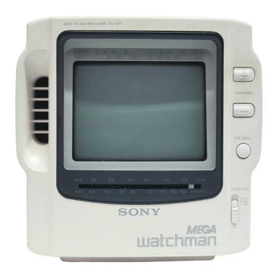
FD-525
FEATURES
4.5inch black and white 90" deflection picture tube.
l
The voltage synthesizer tuning system allows easy tuning.
l
AM/FM tuner is combined.
l
Built-in e-inch
dia. speaker with powerful output and good
l
sound suitable for garden and kitchen use.
Carrying handle for easy carrying.
l
SAFETY-RELATED
COMPONENT
COMPONENTS IDENTIFIED BY MARK A OR DOTTED
LINE WITH MARK A ON THE SCHEMATIC DIAGRAMS
AND IN THE PARTS LIST ARE CRITICAL TO SAFE
OPERATION.
REPLACE THESE COMPONENTS WITH
SONY PARTS WHOSE PART NUMBERS APPEAR AS
SHOWN :lN THIS MANUAL OR IN SUPPLEMENTS PUB-
LISHED BY SONY.
BLACK AND WHITE
TV-AM/FM TUNER
US Model
WARNING!!
Table of Contents

Related Manuals for Sony FD-525


Summary of Contents for Sony FD-525
- Page 1 Use only recommended AC power adaptor. Do not use OPERATION. REPLACE THESE COMPONENTS WITH any other AC adaptor. power SONY PARTS WHOSE PART NUMBERS APPEAR AS SHOWN :lN THIS MANUAL OR IN SUPPLEMENTS PUB- LISHED BY SONY. BLACK AND WHITE Polarity of the plug TV-AM/FM TUNER...
-
Page 2: Table Of Contents
Pinch and remove the anode pin with a pair of tweezers. N O T E O N T H E A N O D E C A P R E M O V A L At this time, be careful not to scratch the anode button. Even when the power switch is off, the voltage at the anode cap is still high. - Page 3 SAFETY CHECK-OUT LEAKAGE TEST After correcting the original service problem, perform the following safety checks before releasing The AC leakage from any exposed metal part to the set to the customer: earth ground and from all exposed metal parts to any Check the area of your repair for unsoldered or exposed metal part having a return to chassis, must poorly-soldered connections.
-
Page 4: Power Sources
To indicate the current channel T e l e s c o p i c a n t e n n a P r e s s t h e C H C A L L b u t t o n . T h e l i n e a p p e a r s e t t h e p o s i t i o n o f the c u r r e n t c h a n n e l B R T ( b r i g h t n e s s ) mntrcl POWER swkch... -
Page 5: Watching The Tv
Outdoor antenna Monitoring the video camera recorder After connecting as illustrated, turn on the power d the equipment and tune in the channel 3 or 4. antenna cable F-type Antenna cable EAC-110 Press the POWER switch. Set the MODE selector to FM or AM. MODE RADIO TUNING... -
Page 6: Disassembly
SECTION 2 DISASSEMBLY Note : Follow the disassembly procedure in the numerical order given. 2-3. CATHODE-RAY TUBE 2-1. CABINET (REAR) battery case lid C board CRT retainer spring 0 PTP3XB 2-2. A BOARD board 2-5. POINTER SETTING board pointer to the ditch of left edge. -
Page 7: Electrical Adjustments
SECTION 3 ELECTRICAL ADJUSTMENTS 3-1. TUNER SECTION FM FREQUENCY COVERAGE A D J U S T M E N T FM Section Adjust for a maximum reading on VTVM. Setting : MODE switch : FM FM rf signal generator antenna Adjust for a maximum reading on VTVM. -
Page 8: Tv Section
Adjustment Location : A board (component side) 3-2. TV SECTION Setting : : TV MODE switch TV BAND switch : VHF or UHF Centering Adjustment Procedures : Tune in off-the-air signal. Adjust the centering magnet so that the picture is in the center. - Page 9 : B board (conductor side) Adjustment Location TUNING AOJ...
-
Page 10: Diagrams
SECTION 4 DIAGRAMS 4-1. SEMICONDUCTOR LEAD LAYOUTS (TOP VIEW) letter ride cathode anode cathode 1 2 3 4 view) (Top anode... -
Page 15: Schematic Diagram
SECTION 6 ELECTRICAL PARTS L1S-i NOTE : Due to standardization, replacements in Items marked ‘I*” are not stocked since the parts list may be different from the they are seldom required for routine service. Some delay should be anticipated parts specified in the diagrams or the components used on the set. - Page 16 Ref. No. Part No. Description Remark Ref. No. Part No. Description Remark 1-101-005-00 CERAMIC 22000PF 1-101-004-00 CERAMIC 0. OluF FUSE, GLASS TUBE (2A/125V) 1-124-472-11 ELECT < IC > l-101-005-00 CERAMIC 22000PF ’ 0. OOluF CERAMIC 47uF 8-759-982-21 IC RC78105A 2oov l-808-293-11 IC AN5151N 2oov IC451 8-759-702-01 IC NJM386BS...
- Page 17 Ref. No. Part No. Description Remark Description Remark 1-249-428-11 CARBON 2 2 0 1-249-435-11 CARBON 33K 5% 1-249-393-11 CARBON 39K 1% l-215-459-00 METAL 1-249-412-11 CARBON 3 9 0 1-249-437-11 CARBON 47K 5% 1-249-417-11 CARBON R113 1-249-429-11 CARBON 1-249-417-11 CARBON 5. 6K 5% R115 1-249-426-11 CARBON 1-249-429-11...
- Page 18 Ref. No. Part No. Description Remark Ref. No. Part No. Description Remark 100 5% A-3016-362-A R BOARD, COMPLETE 1-249-429-11 CARBON 560K 5% 1-247-897-11 CARBON 1-247-897-11 CARBON 560K 5% SCREW (1.7X4) 4-039-681-01 GEAR, TUNING 1-249-433-11 CARBON 22K 5% 4-039-691-01 KNOB, RADIO TUNING (BLACK) 1-259-882-11 CARBON 4-039-691-11 KNOB, RADIO TUNING (WHITE) 4-039-693-01...
-
Page 19: Rear Cabinet Section
Description Ref. No. Part No. Description Ref. No. Part No. Remark Remark **t*********************** < IC > HARDWARE L 1 ST 7-685-648-79 SCREW +BVTP 3X12 TYPE2 N-S 7-626-323-31 SPRING PIN 4X14 l-402-523-11 ANTENNA, FERRITE-ROD (AM) 7-682-548-04 SCREW +B 3X8 l-406-042-00 COIL, FM OSC 7-685-646-79 SCREW +P 3X8 TYPE2 NON-SLIT * 12-z l-426-074-00 COIL, FM RF (A) -
Page 20: Front Cabinet Section
FD-525 English Sony Corporation in Japan General Audio Group 9-957-689-l 1 Published by Audio Corporate Planning Group...