Sony DP-RF6000 Service Manual
Digital surround processor sony dp-rf6000
Hide thumbs
Also See for DP-RF6000:
- Operating instructions manual (92 pages) ,
- Operating instructions manual (32 pages)
Table of Contents
Quick Links
SERVICE MANUAL
Ver. 1.0 2006. 02
• The DP-RF6000 is the digital surround
processor that comprises the MDR-DS6000.
* The digital surround processor for this system incorporates the Dolby Digital decoder, the Dolby Pro Logic II
decoder, the DTS decoder and the MPEG-2 AAC decoder.
Manufactured under licence from Dolby Laboratories and Digital Theater Systems, Inc.
"Dolby," "Pro Logic," the "AAC" logo and the double-D symbol are trademarks of Dolby Laboratories.
"DTS" and "DTS VIRTUAL " are trademarks of Digital Theater Systems, Inc.
• MDR-DS6000 consists of the following models respectively.
Cordless stereo headphone
Digital surround processor
Sony Corporation
9-887-076-01
Personal Audio Division
2006B02-1
Published by Sony Techno Create Corporation
© 2006.02
MDR-RF6000
DP-RF6000
SPECIFICATIONS
Decoder functions
Virtual surround function
Compression function
Modulation System
Carrier wave frequency
Transmission distance
Frequency response
Distortion rate
Audio inputs
Audio output
Power requirements
Dimensions
Mass
Design and specifications are subject to change without notice.
DP-RF6000
Dolby Digital
Dolby Pro Logic II
DTS
MPEG-2 AAC
OFF
CINEMA
MUSIC
OFF
ON
DSSS
2.412 ~ 2.462 GHz (US, Canadian)
2.412 ~ 2.472 GHz (AEP)
2.417 ~ 2.467 GHz (Korea)
Approx. 30 m (100 ft) of longest
12 – 22,000 Hz
(digital input, sampling frequency 48 kHz)
1% or less (1 kHz)
Optical digital input
(rectangular-type) × 1
Analog input (pin jack left/right) × 1
Optical digital output
(rectangular-type) × 1
DC 9 V
(from the supplied AC power adaptor)
Approx. 182 × 38 × 182 mm
× 1
× 7
(7
1
/
1
/
1
/
in) (w/h/d)
4
2
4
Approx. 345 g
(12.17 oz)
DIGITAL SURROUND PROCESSOR
US Model
Canadian Model
AEP Model
Korea Model
Table of Contents

Related Manuals for Sony DP-RF6000


Summary of Contents for Sony DP-RF6000
-
Page 1: Specifications
Ver. 1.0 2006. 02 AEP Model Korea Model • The DP-RF6000 is the digital surround processor that comprises the MDR-DS6000. * The digital surround processor for this system incorporates the Dolby Digital decoder, the Dolby Pro Logic II decoder, the DTS decoder and the MPEG-2 AAC decoder. -
Page 2: Table Of Contents
IC pins, etc. • Usable with ordinary solder It is best to use only unleaded solder but unleaded solder may also be added to ordinary solder. • Repaier DP-RF6000 with MDR-RF6000. -
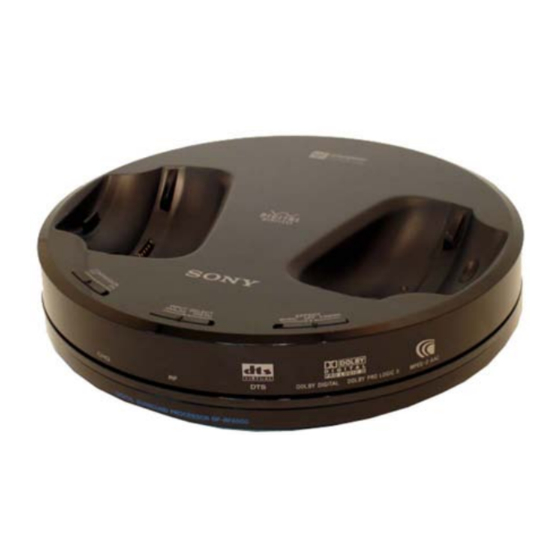
Page 3: General
DP-RF6000 SECTION 1 This section is extracted GENERAL from instruction manual. LOCATING THE CONTROLS Front Panel of the Processor DOLBY DIGITAL DOLBY PRO LOGIC MPEG-2 AAC 1 Contact pin 6 CHG indicator Lights red while charging. 2 Charging lever 7 RF indicator 3 COMPRESSION switch Lights blue while emitting RF signals. -
Page 4: Diagrams
DP-RF6000 SECTION 2 DIAGRAMS NOTE FOR PRINTED WIRING BOARDS AND SCHEMATIC DIAGRAMS. For printed wiring boards. For schematic diagrams. Note: Note: • All capacitors are in µF unless otherwise noted. (p: pF) 50 WV or • X : parts extracted from the component side. -
Page 5: Block Diagrams
DP-RF6000 2-1. BLOCK DIAGRAM ANT4000 IC003 IC052 AUDIO A/D LINE AMP CONVERTER IC1202(2/2) J051 LEVEL SHIFT 8 LIN DSPOUT SDATO FSDATAN1 R-CH LINE IN 7 RIN R-CH R-CH CH/ID SYNC_BUTTON FSCLKN2 S051 S504 ADCLRC TUNE/ID SET MCLK -8dB FSCLKN1,STCCLK2 TX-RF... -
Page 6: Printed Wiring Board - Tx Board Section (Side A)
DP-RF6000 2-2. PRINTED WIRING BOARD – TX BOARD SECTION (SIDE A) – : Uses unleaded solder. TX BOARD (SIDE A) • Semiconductor Location Ref. No. Location D051 D052 D053 D054 D055 D056 D057 D205 D301 D302 D4000 D4001 D4002 D4003... -
Page 7: Printed Wiring Board - Tx Board Section (Side B)
DP-RF6000 2-3. PRINTED WIRING BOARD – TX BOARD SECTION (SIDE B) – : Uses unleaded solder. TX BOARD (SIDE B) • Semiconductor Location Ref. No. Location D521 D522 D523 D524 D525 D526 IC001 G-10 IC004 H-10 MPEG-2 AAC TUNE / ID SET... -
Page 8: Printed Wiring Board - Function, Charge Boards Section
DP-RF6000 2-4. PRINTED WIRING BOARD – FUNCTION, CHARGE BOARDS SECTION – : Uses unleaded solder. BOARD FUNCTION BOARD (SIDE A) (Page 7) CHRGE BOARD 1-868-112- (31) BOARD (Page 7) ANALOG DIGITAL FUNCTION BOARD (SIDE B) INPUT SELECT (31) 1-868-110- EFFECT... -
Page 9: Schematic Diagram - Tx Board Section (1/4)
DP-RF6000 2-5. SCHEMATIC DIAGRAM – TX BOARD SECTION (1/4) – • See page 13, 14 for IC Block Diagrams. 15uH 15uH DP-RF6000... -
Page 10: Schematic Diagram - Tx Board Section (2/4)
DP-RF6000 2-6. SCHEMATIC DIAGRAM – TX BOARD SECTION (2/4) – • See page 14 for IC Block Diagrams. • See page 4 for Waveforms. • See page 15 for IC Pin Function Discription. DP-RF6000... -
Page 11: Schematic Diagram - Tx Board Section (3/4)
DP-RF6000 2-7. SCHEMATIC DIAGRAM – TX BOARD SECTION (3/4) – • See page 17 for IC Pin Function Discription. DP-RF6000... -
Page 12: Schematic Diagram - Tx Board Section (3/4)
DP-RF6000 2-8. SCHEMATIC DIAGRAM – TX (4/4), FUNCTION, CHARGE BOARDS SECTION – • See page 13 for IC Block Diagrams. DP-RF6000... - Page 13 DP-RF6000 • IC BLOCK DIAGRAMS IC305 XC6365A253MR V OUT PHASE ERROR AMP . COMPENSATION COMPARATOR BUFFER, EXT/ DRIVER RAMP WAVE VREF WITH PWM/PFM GENERATOR SOFT START, CONTROLLER IC4002 XC9201D09AKR EXT TIMMING CURRENT V SS CONTROL LIMIT LOGIC PROTECTION V OUT...
- Page 14 DP-RF6000 IC4004 XC6365B103MR PHASE ERROR AMP . COMPENSATION COMPARATOR BUFFER, EXT/ DRIVER RAMP WAVE VREF WITH PWM/PFM GENERATOR SOFT START, CONTROLLER IC4006 XC6219B332MR VOLTAGE REFERENCE CURRENT LIMIT VOUT ON/OFF CONTROL EACH CIRCUIT...
-
Page 15: Ic Pin Function Descriptions
DP-RF6000 2-9. IC Pin Function Descriptions • IC201 MB90488BPFV-G-150E1 SYSTEM CONTROL (TX BOPARD) Pin No. Pin Name Description 1 to 8 P22 to P27, P30, P31 — Not used (Open) — Ground — Not used (Open) COMPRESSION switch signal input (L : ON,H:OFF) - Page 16 DP-RF6000 Pin No. Pin Name Description XRST System reset signal input Reset signal output to LC89052T-TLM-E — Not used (Open) — Not used (Connect to Ground) — Ground Clock output (4MHz) Clock input (4MHz) VCC3 — Power supply (+3.3V) REG+9V Main Power supply ON/OFF signal output...
- Page 17 DP-RF6000 • IC1201 CS494003-CQZ DECODER/DSP (TX BOARD) Pin No. Pin Name Description UHS0 Mode select signal input UHS1 Mode select signal input XINTREQ DSP Interrupt request signal output to MB90488BPFV-G-150E1 FSCDIN Serial data input from MB90488BPFV-G-150E1 GPIO20 — Not used (Open)
- Page 18 DP-RF6000 Pin No. Pin Name Description CLKOUT — Not used (Open) — Not used (Open) CLKIN Not used (Pull up) 62,63 A8, A7 — Not used (Open) CLKEN — Not used (Open) 65 to 67 A6 to A4 — Not used (Open) SD_CS —...
- Page 19 DP-RF6000 Pin No. Pin Name Description GPIO9 — Not used (Open) GPIO13 — Not used (Open) FSDATAN1 Serial A/D data input from WM8738GED/R VDD4 — Power supply (+2.5V) VSS4 — Ground FSCLKN1, STCCLK2 Serial clock signal input from LC98052T-TLM-E XSCS...
-
Page 20: Exploded Views
DP-RF6000 SECTION 3 EXPLODED VIEWS NOTE: • The mechanical parts with no reference number • Abbreviation • -XX, -X mean standardized parts, so they may in the exploded views are not supplied. CND : Canadian model have some differences from the original one. -
Page 21: Electrical Parts List
DP-RF6000 CHARGE FUNCTION SECTION 4 ELECTRICAL PARTS LIST NOTE: When indicating parts by reference • RESISTORS • Due to standardization, replacements in the number, please include the board. All resistors are in ohms. parts list may be different from the parts... - Page 22 DP-RF6000 Ref. No. Part No. Description Remarks Ref. No. Part No. Description Remarks C208 1-162-964-11 CERAMIC CHIP 0.001uF C1212 1-104-655-91 ELECT 470uF 6.3V C209 1-107-826-11 CERAMIC CHIP 0.1uF C1213 1-124-584-00 ELECT 100uF C210 1-107-826-11 CERAMIC CHIP 0.1uF C211 1-107-826-11 CERAMIC CHIP 0.1uF...
- Page 23 DP-RF6000 Ref. No. Part No. Description Remarks Ref. No. Part No. Description Remarks D523 8-719-059-98 DIODE SLR-342VC3F (DOLBY PRO LOGIC II) L1201 1-412-953-11 INDUCTOR 15uH D524 8-719-059-98 DIODE SLR-342VC3F (DTS) D525 8-719-059-98 DIODE SLR-342VC3F (MPEG-2 AAC) L1202 1-414-760-21 INDUCTOR, FERRITE BEAD...
- Page 24 DP-RF6000 Ref. No. Part No. Description Remarks Ref. No. Part No. Description Remarks R054 1-216-841-11 METAL CHIP 1/10W R1244 1-216-827-11 METAL CHIP 3.3K 1/10W R055 1-218-345-11 METAL CHIP 9.1K 1/10W R1245 1-216-827-11 METAL CHIP 3.3K 1/10W R056 1-218-345-11 METAL CHIP 9.1K...
- Page 25 DP-RF6000 MEMO...
- Page 26 DP-RF6000 REVISION HISTORY Clicking the version allows you to jump to the revised page. Also, clicking the version at the upper right on the revised page allows you to jump to the next revised page. Ver. Date Description of Revision...