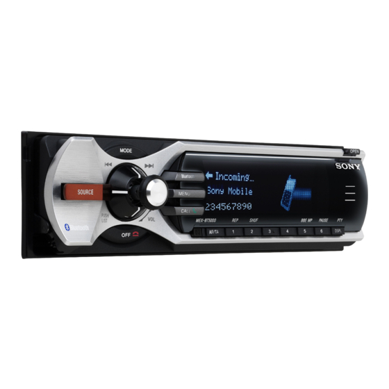
Sony MEX-BT5000 Service Manual
Bluetooth audio system
Hide thumbs
Also See for MEX-BT5000:
- Installation manual ,
- Operating instructions manual (204 pages) ,
- Installation/connections (2 pages)
Table of Contents
Quick Links
SERVICE MANUAL
Ver. 1.0 2006.06
US and foreign patents licensed from Dolby
Laboratories.
Manufactured under license
from BBE Sound, Inc.
R
The BBE MP process
improves digitally compressed sound, such as
MP3, by restoring and enhancing the higher
harmonics lost through compression. BBE MP
works by generating even-order harmonics from
the source material, effectively recovering
warmth, detail and nuance.
The "SAT Radio Ready"
logo indicates that this
product will control a
satellite radio tuner module
(sold separately). Please see your nearest
authorized Sony dealer for details on the
satellite radio tuner module.
"SAT Radio," "SAT Radio Ready," the SAT
Radio and SAT Radio Ready logos and all
related marks are trademarks of Sirius Satellite
Radio Inc. and XM Satellite Radio Inc.
The Bluetooth word mark and logos are owned
by the Bluetooth SIG, Inc. and any use of such
marks by Sony Corporation is under license.
Other trademarks and trade names are those of
their respective owners.
SonicStage and its logo are trademarks of Sony
Corporation.
"ATRAC" and
are trademarks of
Sony Corporation.
Microsoft, Windows Media,
and the Windows logo are
trademarks or registered
trademarks of Microsoft
Corporation in the United States and/or other
countries.
Sony Corporation
9-887-268-01
eVehicle Division
2006F05-1
Published by Sony Techno Create Corporation
© 2006.06
MEX
Model Name Using Similar Mechanism
CD Mechanism Type
Optical Pick-up Name
SPECIFICATIONS
AUDIO POWER SPECIFICATIONS
(US, Canadian only)
POWER OUTPUT AND TOTAL HARMONIC
DISTORTION
23.2 watts per channel minimum continuous
average power into 4 ohms, 4 channels driven
from 20 Hz to 20 kHz with no more than 5% total
harmonic distortion.
CEA2006 Standard
Power Output: 17 Watts RMS × 4 at
4 Ohms < 1% THD+N
SN Ratio: 82 dBA
(reference: 1 Watt into 4 Ohms)
CD Player section
Signal-to-noise ratio: 120 dB
Frequency response: 10 − 20,000 Hz
Wow and flutter: Below measurable limit
Tuner section (US, Canadian)
FM
Tuning range: 87.5 − 107.9 MHz
Antenna terminal: External antenna connector
Intermediate frequency: 10.7 MHz/450 kHz
Usable sensitivity: 9 dBf
Selectivity: 75 dB at 400 kHz
Signal-to-noise ratio: 67 dB (stereo), 69 dB (mono)
Harmonic distortion at 1 kHz: 0.5 % (stereo),
0.3 % (mono)
Separation: 35 dB at 1 kHz
Frequency response: 30 − 15,000 Hz
AM
Tuning range: 530 − 1,710 kHz
Antenna terminal: External antenna connector
Intermediate frequency: 10.7 MHz/450 kHz
Sensitivity: 30 µV
BLUETOOTH AUDIO SYSTEM
BT5000
-
US Model
Canadian Model
AEP Model
UK Model
MEX-1GP
MG-611WA-186//Q
KSS1000E
Tuner section (AEP, UK)
FM
Tuning range: 87.5 − 108 MHz
Aerial terminal: External aerial connector
Intermediate frequency: 10.7 MHz/450 kHz
Usable sensitivity: 9 dBf
Selectivity: 75 dB at 400 kHz
Signal-to-noise ratio: 67 dB (stereo), 69 dB (mono)
Harmonic distortion at 1 kHz: 0.5 % (stereo),
0.3 % (mono)
Separation: 35 dB at 1 kHz
Frequency response: 30 − 15,000 Hz
MW/LW
Tuning range:
MW: 531 − 1,602 kHz
LW: 153 − 279 kHz
Aerial terminal: External aerial connector
Intermediate frequency: 10.7 MHz/450 kHz
Sensitivity: MW: 30 µV, LW: 40 µV
Tuner section (E)
FM
Tuning range:
87.5 − 108.0 MHz (at 50 kHz step)
87.5 − 107.9 MHz (at 200 kHz step)
FM tuning interval: 50 kHz/200 kHz switchable
Aerial terminal: External aerial connector
Intermediate frequency: 10.7 MHz/450 kHz
Usable sensitivity: 9 dBf
Selectivity: 75 dB at 400 kHz
Signal-to-noise ratio: 67 dB (stereo), 69 dB (mono)
Harmonic distortion at 1 kHz: 0.5 % (stereo),
0.3 % (mono)
Separation: 35 dB at 1 kHz
Frequency response: 30 − 15,000 Hz
AM
Tuning range:
531 − 1,602 kHz (at 9 kHz step)
530 − 1,710 kHz (at 10 kHz step)
AM tuning interval: 9 kHz/10 kHz switchable
Aerial terminal: External aerial connector
Intermediate frequency: 10.7 MHz/450 kHz
Sensitivity: 30 µV
– Continued on next page –
E Model
Table of Contents

Related Manuals for Sony MEX-BT5000


Summary of Contents for Sony MEX-BT5000
-
Page 1: Specifications
FM tuning interval: 50 kHz/200 kHz switchable Selectivity: 75 dB at 400 kHz Aerial terminal: External aerial connector SonicStage and its logo are trademarks of Sony Signal-to-noise ratio: 67 dB (stereo), 69 dB (mono) Intermediate frequency: 10.7 MHz/450 kHz Corporation. - Page 2 Fraunhofer IIS and Thomson. Note This unit cannot be connected to a digital preamplifier or an equalizer which is Sony BUS system compatible. Design and specifications are subject to change without notice. • AEP, UK, E model...
-
Page 3: Table Of Contents
MEX-BT5000 TABLE OF CONTENTS SERVICING NOTES ..........4 GENERAL ..............6 DISASSEMBLY 3-1. Disassembly Flow ............16 3-2. Front Back Panel Assy ............ 16 3-3. KEY Board ..............17 3-4. Sub Panel Assy ..............17 3-5. CD Mechanism Block (MG-611WA-186//Q) ....18 3-6. -
Page 4: Servicing Notes
MEX-BT5000 SECTION 1 SERVICING NOTES UNLEADED SOLDER NOTES ON HANDLING THE OPTICAL PICK-UP Boards requiring use of unleaded solder are printed with the lead- BLOCK OR BASE UNIT free mark (LF) indicating the solder contains no lead. The laser diode in the optical pick-up block may suffer electrostatic... - Page 5 [1] t [2] ([2] is pressed for two seconds) to the USB memory. (The USB memory is a thing to prepare the one of about 64MB made of SONY POCKET BIT.) button of the set sequentially, and disc slot is unlocked.
-
Page 6: General
MEX-BT5000 SECTION 2 This section is extracted from instruction manual. GENERAL (US, Canadian) Location of controls and basic operations Refer to the pages listed for details. The C MODE button Audio function corresponding buttons on the card remote To select the radio band (FM/AM)/select the... - Page 7 MEX-BT5000 Bluetooth function D MENU button Refer to the pages listed for details. The corresponding buttons on the card remote To enter menu; receive a call. Main unit commander control the same functions as those E Display window on the unit.
- Page 8 MEX-BT5000 (AEP, UK) Location of controls and basic operations Audio function Refer to the pages listed for details. The Radio: Push up/down to: corresponding buttons on the card remote − Receive stored station. Main unit commander control the same functions as those Push left/right to: on the unit.
- Page 9 MEX-BT5000 Bluetooth function D MENU button Refer to the pages listed for details. The corresponding buttons on the card remote To enter menu; receive a call. Main unit commander control the same functions as those E Display window on the unit.
- Page 10 MEX-BT5000 Location of controls and basic operations Audio function Refer to the pages listed for details. The Radio: corresponding buttons on the card remote Push up/down to: − Receive stored station. Main unit commander control the same functions as those on the unit.
- Page 11 MEX-BT5000 Bluetooth function D MENU button Refer to the pages listed for details. The corresponding buttons on the card remote To enter menu; receive a call. Main unit commander control the same functions as those E Display window on the unit.
-
Page 12: Connection Diagram
MEX-BT5000 (US, Canadian, E) 6 To the +12 V power terminal which is Cautions energized in the accessory position of the ignition key switch Notes • If there is no accessory position, connect to the +12 V Be sure to install this unit in the dashboard of the car power (battery) terminal which is energized at all times. - Page 13 Before installing the unit, remove the protection You may not be able to install this unit in some makes of collar 4 and the bracket 1 from the unit. Japanese cars. In such a case, consult your Sony dealer. Note Remove the protection collar 4.
- Page 14 MEX-BT5000 (AEP, UK) BUS AUDIO IN AUDIO OUT FRONT BUS CONTROL IN UB OUT ( MONO ) BUS AUDIO IN AUDIO OUT REAR Source selector* XA-C40 BUS CONTROL IN * not supplied Note for the aerial connecting If your car aerial is an ISO (International Organisation for Standardisation) type, use the supplied adaptor 2 to connect it.
- Page 15 MEX-BT5000 Face the hook inwards. Dashboard 1 8 2 Fire wall 5 3 m Claws Precautions 6-B To attach Place the hole A in the front panel onto the spindle B • Choose the installation location carefully so that the on the unit, as illustrated, then push the left side in.
-
Page 16: Disassembly
MEX-BT5000 SECTION 3 DISASSEMBLY • This set can be disassembled in the order shown below. 3-1. DISASSEMBLY FLOW SET (FRONT PANEL BLOCK) SET (MAIN BLOCK) 3-2. FRONT BACK PANEL ASSY 3-4. SUB PANEL ASSY (Page 16) (Page 17) 3-3. KEY BOARD 3-5. -
Page 17: Key Board
MEX-BT5000 3-3. KEY BOARD Note1: Please use a hexagon head wrench of 0.89mm when you remove hexagon socket set screw. 3 KEY board Note2: Please tighten by the torque of 1.5k when you install hexagon socket set screw. 1 hexagon socket set screw 2 knob assy (S) 3-4. -
Page 18: Cd Mechanism Block (Mg-611Wa-186//Q)
MEX-BT5000 3-5. CD MECHANISM BLOCK (MG-611WA-186//Q) 7 CD mechanism block 6 bracket (CD) (MG-611WA-186//Q) 5 two screws (PTT2.6 × 4) 2 screw (PTT2.6 × 6) 1 screw (PTT2.6 × 6) 4 connector (CNP501) 3-6. MAIN BOARD 4 screw (PTT2.6 × 8) -
Page 19: Antenna Board, It Board
MEX-BT5000 3-7. ANTENNA BOARD, IT BOARD 7 three ground point screws (PTT2.6 × 6) 9 shield plate (IT A) 4 coaxial cable (ANTENNA board: CN1, q; Remove the four solders. IT board) qf IT board qd radiation sheet (SH) qs shield plate... -
Page 20: Roller Arm Assy
MEX-BT5000 3-9. ROLLER ARM ASSY 3 washer 5 roller arm assy 4 gear (RA1) 2 spring (RAR-B) 1 spring (RAL-B) 3-10. CHASSIS (OP) ASSY 9 chassis (OP) assy 8 coil spring (damper) lever (D) 1 optical pick-up flexible board (16 core) -
Page 21: Optical Pick-Up (Kss1000E)
MEX-BT5000 3-11. OPTICAL PICK-UP (KSS1000E) 2 chucking arm sub assy 5 claw 1 tension coil spring (CHKG) 7 optical pick-up (KSS1000E) 6 main shaft 4 rack (SL) 3 screw (B1.4 × 5) 3-12. SL MOTOR ASSY (SLED) (M902) 1 screw (P1.4 ×... -
Page 22: Le Motor Assy (B) (Loading) (M903)
MEX-BT5000 3-13. LE MOTOR ASSY (B) (LOADING) (M903) 7 screw (M1.7 × 2.5) 9 gear (LE) assy 8 bearing (LEB-N) q; screw (M1.7 × 2.5) qd two toothed lock screws 2 gear (LE1) (M1.4) qf LE motor lever (D) assy (B) -
Page 23: Test Mode
3 histories or less. 051 CD error information (error content + error detailed) (History 1) button of the set sequentially, and enter the service mode. The SONY BUS slave unit that becomes an object is CD Joystick to up Joystick to down 4. -
Page 24: Diagrams
MEX-BT5000 SECTION 5 DIAGRAMS 5-1. BLOCK DIAGRAM – CD SERVO Section – • R-ch is omitted due to same as L-ch. • Signal Path : CD PLAY DETECTOR (Page 26) FPI2 AGCI RFEQO CD_L RFRPI R-CH FNI2 FPI1 FNI1 RF AMP,DIGITAL SERVO,... -
Page 25: Block Diagram - Bluetooth Section
MEX-BT5000 5-2. BLOCK DIAGRAM – BLUETOOTH Section – BLUETOOTH MODULE IC500 PATTERN ANTENNA • R-ch is omitted due to same as L-ch. A-OUT_N_L LINE AMP (Page 26) BT_L • Signal Path IC504 A-OUT_P_L : AUDIO A-OUT_N_R MIC500 R-CH A-IN_N_L DATA BUS INTERFACE... -
Page 26: Block Diagram - Audio Section
MEX-BT5000 5-3. BLOCK DIAGRAM – AUDIO Section – AUDIO SELECT IC302 ELECTRICAL VOLUME PJ301 IC301 (2/2) (Page 24) CD_L IN1B OUTLF 20 OUTB 11 SE1L AUDIO OUT (Page 25) FRONT BT_L IN2B R-CH DIFFL OUTLR 19 AUDIO OUT REAR R-CH... -
Page 27: Block Diagram - Display/Main Section
UNI_CLK LATCH (Page 24) GCP1 UNI_SI OR GATE GCP2 UNI_SO IC705 GCP3 BU_IN LINK_OFF CNP102 LED801 – 803 SONY BUS INTERFACE BT_LED1, BUS CONTROL IN LED DRIVE IC102 BT_LED2, BU-IN BLUETOOTH Q801 – 803 BT_LED3 INDICATOR DATA B-DATA (Page 28) -
Page 28: Block Diagram - Power Supply Section
MEX-BT5000 5-5. BLOCK DIAGRAM – POWER SUPPLY Section – REGULATOR IC201 (2/2) +8.4V REG1 B+ SWITCH USB_EN (Page 25) RDS +3.3V Q403, 404 USB_OCP (Page 26) HIGH-SIDE VBUS SWITCH +3.3V IC522 BU +3.3V REGULATOR IC504 +3.3V +3.3V SYSTEM CONTROLLER REGULATOR FL +3.3V... - Page 29 MEX-BT5000 • Note for Printed Wiring Boards and Schematic Diagrams • Circuit Boards Location Note on Printed Wiring Board: Note on Schematic Diagram: • X : parts extracted from the component side. • All capacitors are in µF unless otherwise noted. (p: pF) •...
-
Page 30: Schematic Diagram - Servo Section (1/2)
MEX-BT5000 • See page 41 for Waveforms. • See page 47 for IC Block Diagrams. • See page 52 for IC Pin Function Description. 5-6. SCHEMATIC DIAGRAM – SERVO Section (1/2) – TP33 TP32 IC B/D TP31 TP52 TP38 TP39... -
Page 31: Schematic Diagram - Servo Section (2/2)
MEX-BT5000 • See page 41 for Waveforms. • See page 47 for IC Block Diagrams. • See page 52 for IC Pin Function Description. 5-7. SCHEMATIC DIAGRAM – SERVO Section (2/2) – (Page 30) (Page 39) CNP501 TP74 TP88 TP75... -
Page 32: Printed Wiring Boards - Servo Section
MEX-BT5000 • See page 29 for Circuit Boards Location. 5-8. PRINTED WIRING BOARDS – SERVO Section – : Uses unleaded solder. TP39 TP38 TP26 TP24 TP41 FMB3 FMA6 TP23 TP29 TP42 TP43 TP45 TP44 TP27 TP37 TP46 TP53 TP36 TP48... -
Page 33: Printed Wiring Board - It Board
MEX-BT5000 • See page 29 for Circuit Boards Location. 5-9. PRINTED WIRING BOARD – IT Board – : Uses unleaded solder. ANTENNA BOARD ANTENNA BOARD (COMPONENTSIDE) (CONDUCTORSIDE) • Semiconductor 1-869-288 - Location Ref. No. Location (12) 1-869-288 - 12 D500... -
Page 34: Schematic Diagram - It Board (1/2)
MEX-BT5000 • See page 41 for Waveforms. • See page 47 for IC Block Diagrams. 5-10. SCHEMATIC DIAGRAM – IT Board (1/2) – (1/2) CN504 RB500 R554 4.7k 4.7k TRST TRST ASEBRKAK C532 R539 R556 ASEBRKAK 1.8k AUDO_NR (NC) R552... -
Page 35: Schematic Diagram - It Board (2/2)
MEX-BT5000 • See page 41 for Waveforms. • See page 47 for IC Block Diagrams. • See page 52 for IC Pin Function Description. 5-11. SCHEMATIC DIAGRAM – IT Board (2/2) – MAS_RST (2/2) IC516 TC7WBL126FK(T5RS BUS SWITCH IC513 S-1170B19UC +1.9V REGULATOR... -
Page 36: Main Board (Component Side)
MEX-BT5000 • See page 29 for Circuit Boards Location. 5-12. PRINTED WIRING BOARD – MAIN Board (Component Side) – : Uses unleaded solder. • Semiconductor Location Ref. No. Location Ref. No. Location D101 D102 IC101 D103 IC102 D104 IC301 D105... -
Page 37: Printed Wiring Board - Main Board (Conductor Side)
MEX-BT5000 • See page 29 for Circuit Boards Location. 5-13. PRINTED WIRING BOARD – MAIN Board (Conductor Side) – : Uses unleaded solder. PJ301 BUS AUDIO AUDIO AUDIO (FRONT VIEW) AUX IN REAR FRONT CNP102 CNJ351 MAIN BOARD BUS CONTROL... -
Page 38: Schematic Diagram - Main Board (1/3)
MEX-BT5000 • See page 41 for Waveforms. • See page 47 for IC Block Diagrams. 5-14. SCHEMATIC DIAGRAM – MAIN Board (1/3) – Q301-305 (1/3) EEPROM MUTING TUX401 TUX032//Q PJ301 (TUNER UNIT) Q301 ELECTRICAL VOLUME DTC614TK C328 100p AUDIO OUT... -
Page 39: Schematic Diagram - Main Board (2/3)
MEX-BT5000 • See page 41 for Waveforms. • See page 47 for IC Block Diagrams. • See page 52 for IC Pin Function Description. 5-15. SCHEMATIC DIAGRAM – MAIN Board (2/3) – (2/3) (Page (Page 38) MUTE +3.3V REGULATOR SYS_RST... -
Page 40: Schematic Diagram - Main Board (3/3)
MEX-BT5000 • See page 47 for IC Block Diagrams. 5-16. SCHEMATIC DIAGRAM – MAIN Board (3/3) – (3/3) Q116 DTC144EKA R144 C103 L101 L103 3300 C104 D114 0µH TH101 0.22 1N5404TU 47µH D124 RB751V R130 R143 BUS INTERFACE CONTROL D122... - Page 41 MEX-BT5000 • Waveforms – SERVO Board – – IT Board – – MAIN Board – – KEY Board – IC2 5 (FEI) IC3 ia (X1) IC506 qd (XTAL1) IC401 q; (XTO) IC704 qd (X2) Approx. 1.1 Vp-p 1.5 Vp-p 1.9 Vp-p 2.3 Vp-p...
-
Page 42: Printed Wiring Board - Sub Board
MEX-BT5000 • See page 29 for Circuit Boards Location. 5-17. PRINTED WIRING BOARD – SUB Board – : Uses unleaded solder. SUB BOARD (COMPONENT SIDE) LED902, 903 S901 LED903 DISC SLOT ILLUMINATION D903 CN902 D902 (12) 1-869-287- LED902 ILLUMINATION KEY BOARD... -
Page 43: Schematic Diagram - Sub Board
MEX-BT5000 5-18. SCHEMATIC DIAGRAM – SUB Board – LED902 LED903 CL-190UB2- CL-270UB2- DISC SLOT ILLUMINATION ILLUMINATION CN901 D902 D903 R903 UDZSTE UDZSTE -176.8B -176.8B DOOR_IND(+BATT) FL-F1(+,+4.3) FL-VSS FL-VDD2(+55V) S901 FL-F2(-,+1.0V) FL-VDD1(3.3V) LED+10V CN902 DOOR_SW RE_IN0 DOOR_SW RE_IN1 FL-F1(+,+4.3) KEY_0 FL-VSS... -
Page 44: Schematic Diagram - Key Board (1/2)
MEX-BT5000 • See page 41 for Waveforms. • See page 47 for IC Block Diagrams. • See page 52 for IC Pin Function Description. 5-19. SCHEMATIC DIAGRAM – KEY Board (1/2) – (1/2) R719 100k ENC702(1/2) (Page R751 C711 R704... -
Page 45: Schematic Diagram - Key Board (2/2)
MEX-BT5000 5-20. SCHEMATIC DIAGRAM – KEY Board (2/2) – (2/2) LED801-803 (Page 44) (BLUETOOTH INDICATOR) R811 R812 R801 R802 R803 R804 R805 R806 R807 R808 R809 R810 1.5k 1.5k 1.5k 1.5k 1.5k 1.5k 1.5k 1.5k 2.2k 2.2k 2.2k 2.2k LED803... -
Page 46: Printed Wiring Board - Key Board
MEX-BT5000 • See page 29 for Circuit Boards Location. 5-21. PRINTED WIRING BOARD – KEY Board – : Uses unleaded solder. KEY BOARD (COMPONENT SIDE) LED815, S708 LED815 MODE S708 LED817 LED812, S705 Bluetooth R827 LED805, S702 Q801 S705 LED812 SOURCE LED801 –... -
Page 47: Ic Block Diagrams
MEX-BT5000 • IC Block Diagrams – SERVO Board – IC1 BA5968FP-E2 OPIN4+ LDCTL OUTR OUTF OPIN4– OPOUT1 OPOUT4 OPIN3+ OPIN3– OPOUT2 OPOUT3 POWVCC MUTE MUTE VOL– VOL+ VOL+ VOL2– VOL3– LEVEL LEVEL SHIFT SHIFT VOL2+ VOL3+ VO1– VOL4– LEVEL LEVEL... - Page 48 MEX-BT5000 IC506 XR16L2550IM-F 48 47 46 45 44 43 42 41 40 39 38 37 36 RESET TRANSMIT SHIFT RESISTER (THR/FIFO) RECEIVER SHIFT RESISTER TXRDYB# (RHR/FIFO) 8-bit DATA OP2B# 35 DTRB# CSA# 34 DTRA# INTERFACE MODEM CSB# GENERAL NC 12...
- Page 49 MEX-BT5000 – MAIN Board – IC101 BD9300FV-FE2 IC102 BA8271F-E2 14 NON 13 1/2VREF – 12 INV 11 VREF VREF 10 CTL RESET SWITCH – – N.C. TIMER 9 SCP LATCH 8 VCC IC301 TDA7419TR AUOUTR/ AC2OUTR ACINR/ FILOR ACINL/ FILOL...
- Page 50 MEX-BT5000 IC302 NJM2750M-TE2 IN1A 1 CNT1 2 IN2A 3 OUTA CNT2 4 IN4A 5 IN3A LOGIC BIAS VREF IN1B IN2B 7 OUTB IN4B 8 IN3B IC401 TDA7333013TR 16 MPX VDDA 15 INTN REF3 14 CSN SIGMA DELTA REF2 CONVERTER 13 SA_DATAOUT...
- Page 51 MEX-BT5000 IC601 BD9851EFV-E2 SEL1 20 GND BOTH CH 19 STB ON/OFF – – 18 VCC VREF 17 VREF (2.5V) – NON2 16 INV1 – INV2 – 15 FB1 TIMER 14 SCP LATCH 13 DTC1 12 PVCC1 11 OUT1 – –...
- Page 52 MEX-BT5000 • IC Pin Function Description SERVO BOARD IC2 TC94A70FG-002 (RF AMP, DIGITAL SERVO, DIGITAL SIGNAL PROCESSOR) Pin No. Pin Name Description AVSS3 Ground terminal RFZI RF ripple zero crossing signal input terminal RFRP RF ripple signal output terminal SBAD/RFDC/...
- Page 53 MEX-BT5000 Pin No. Pin Name Description PIO3 Muting on/off control signal input from the CD system control "L": mute VSS1-3 Ground terminal VDDT3-2 Power supply terminal (+3.3 V) SBSY Not used SBOK/FOK Not used Not used SFSY/LOCK Not used ZDET...
- Page 54 MEX-BT5000 Pin No. Pin Name Description FPI1 Main beam input terminal (Connect with pin diode B) Sub beam amplification input terminal (Connect with pin diode F) TNPC Not used Sub beam amplification input terminal (Connect with pin diode E)
- Page 55 47 to 49 MD0 to MD2 CPU operation mode setting terminal BUS_ON SONY bus on/off control signal input terminal "L": bus on BU_IN Back up power supply detection signal input terminal "L" is input at low voltage Not used MEC_SELFSW Disc insert detection switch signal input terminal "L": disc in interruption...
- Page 56 Mechanism deck power supply on/off control signal output terminal CDON CD servo power supply detection output terminal XUART Sony-bus/MC-bus change signal input terminal Not used ZMUTE Muting on/off control signal output to the system controller MECON_CHK CD mecha +6V power rising detection signal input CDON_CHK CD servo +3.3V power rising detection signal input terminal...
- Page 57 MEX-BT5000 IT BOARD IC511 HD6417727F100CV (BLUETOOTH CONTROLLER) Pin No. Pin Name Description VCC-RTC Power supply terminal (+1.9V) XTAL2 System clock input terminal for internal real time clock Not used EXTAL2 System clock output terminal for internal real time clock Not used...
- Page 58 MEX-BT5000 Pin No. Pin Name Description VCCQ Power supply terminal (+3.3V) 78, 79 A13, A14 Address signal output to the SD-RAM and flash ROM 80 to 85 A15 to A20 Address signal output to the flash ROM VSSQ Ground terminal...
- Page 59 MEX-BT5000 Pin No. Pin Name Description SD_CKE Clock enable signal output to the SD-RAM SD_RAS Row address strobe signal output to the SD-RAM PTJ1 Not used SD_CAS Column address strobe signal output to the SD-RAM VSSQ Ground terminal PTJ3 Not used VCCQ Power supply terminal (+3.3V)
- Page 60 MEX-BT5000 Pin No. Pin Name Description Ground terminal Power supply terminal (+1.9V) XTAL System clock input terminal (12.5 MHz) EXTAL System clock output terminal 12.5 MHz) TXRDYA Ready signal input from the data bus interface PINT9 Not used PINT Not used...
- Page 61 MEX-BT5000 Pin No. Pin Name Description EVOL_DATA Serial data input terminal from the audio select 234 to 236 AN3 to AN5 Not used AVCC Power supply terminal (+3.3V) 238, 239 AN5, AN7 Not used AVSS Ground terminal...
- Page 62 GUI_RST Reset signal output to the bluetooth controller, data bus interface and flash rom Muting on/off control signal output terminal SYSRST Reset signal output to the SONY bus interface IC and CD system control VCC5 Power supply terminal (+3.3V) EESIO...
- Page 63 Serial data input from the SONY bus interface IC UNISO Serial data output to the SONY bus interface IC UNISCK Serial data transfer clock signal output to the SONY bus interface IC and CD system control 59, 60 Not used DOOR_IND LED drive signal output terminal for sub panel LED "H": LED on...
- Page 64 MEX-BT5000 Pin No. Pin Name Description CDMUTE_IN Muting on/off control signal input from the CD system control CDON_IN CD servo power supply detection input terminal CDMON_IN CD mecha power supply detection input terminal TEST_IN Test mode setting terminal "L": test mode DEBUG Debug mode setting terminal "H": debug mode...
- Page 65 MEX-BT5000 KEY BOARD IC704 uPD70F3263GC-B500-8EA-A (FRONT PANEL CONTROLLER) Pin No. Pin Name Description AVREF0 Reference voltage (+3.3V) input terminal (for A/D conversion) AVSS Ground terminal 3, 4 Not used AVREF1 Reference voltage (+3.3V) input terminal (for D/A conversion) 6, 7...
- Page 66 MEX-BT5000 Pin No. Pin Name Description 58 to 67 Not used ENC_SEL Terminal for encoder identification "H": Made in the alps, "L": Made in the hoshiden BVSS Ground terminal BVDD Power supply terminal (+3.3V) BT_LED1 LED drive signal output terminal for bluetooth indicator KEY0_SW Bus switch control signal output terminal "H": bus switch active (KEY0 is reading enable)
-
Page 67: Exploded Views
MEX-BT5000 SECTION 6 EXPLODED VIEWS NOTE: • -XX and -X mean standardized parts, so they • Items marked “*” are not stocked since they The components identified by mark 0 or dotted line with mark 0 are may have some difference from the original are seldom required for routine service. -
Page 68: Front Panel Section
MEX-BT5000 6-2. FRONT PANEL SECTION ENC702 not supplied supplied FL701 not supplied not supplied not supplied (KEY board) not supplied not supplied not supplied not supplied not supplied not supplied not supplied not supplied not supplied Ref. No. Part No. -
Page 69: Cd Mechanism Deck Section-1 (Mg-611Wa-186//Q)
MEX-BT5000 6-3. CD MECHANISM DECK SECTION-1 (MG-611WA-186//Q) not supplied (SENSOR board) not supplied not supplied not supplied CD mechanism deck section-2 (MG-611WA-186//Q) not supplied CD mechanism deck section-3 (MG-611WA-186//Q) Ref. No. Part No. Description Remark Ref. No. Part No. Description... -
Page 70: Cd Mechanism Deck Section-2 (Mg-611Wa-186//Q)
MEX-BT5000 6-4. CD MECHANISM DECK SECTION-2 (MG-611WA-186//Q) (including spindle motor (M901)) not supplied M902 not supplied (spindle motor not supplied (M901)) supplied not supplied not supplied not supplied Ref. No. Part No. Description Remark Ref. No. Part No. Description Remark... -
Page 71: Cd Mechanism Deck Section-3 (Mg-611Wa-186//Q)
MEX-BT5000 6-5. CD MECHANISM DECK SECTION-3 (MG-611WA-186//Q) M903 CD mechanism deck section-4 (MG-611WA-186//Q) Ref. No. Part No. Description Remark Ref. No. Part No. Description Remark 2-186-696-22 BRACKET (LEM-N) 3-348-993-01 WASHER 2-186-699-21 GEAR (RA1) 3-345-648-91 SCREW (M1.4), TOOTHED LOCK A-1075-641-D ARM ASSY, ROLLER... -
Page 72: Cd Mechanism Deck Section-4 (Mg-611Wa-186//Q)
MEX-BT5000 6-6. CD MECHANISM DECK SECTION-4 (MG-611WA-186//Q) Ref. No. Part No. Description Remark Ref. No. Part No. Description Remark 2-186-700-21 GEAR (CHK1) 2-590-545-34 GEAR (LE2-M) 3-259-470-33 GEAR (LE1) A-1075-640-C CHASSIS (M) BLOCK ASSY 3-253-755-43 LEVER (D) 3-348-993-01 WASHER... -
Page 73: Electrical Parts List
MEX-BT5000 SECTION 7 ANTENNA ELECTRICAL PARTS LIST NOTE: • Due to standardization, replacements in the • Items marked “*” are not stocked since they The components identified by mark 0 or dotted line with mark 0 are parts list may be different from the parts are seldom required for routine service. - Page 74 MEX-BT5000 Ref. No. Part No. Description Remark Ref. No. Part No. Description Remark C614 1-164-931-11 CERAMIC CHIP 100PF < FILTER > C615 1-107-820-11 CERAMIC CHIP 0.1uF E500 1-469-987-21 FILTER, EMI REMOVAL (SMD) C616 1-107-820-11 CERAMIC CHIP 0.1uF C617 1-107-820-11 CERAMIC CHIP 0.1uF...
- Page 75 MEX-BT5000 Ref. No. Part No. Description Remark Ref. No. Part No. Description Remark R514 1-218-990-11 SHORT CHIP R607 1-218-977-11 RES-CHIP 100K 1/16W R515 1-218-990-11 SHORT CHIP R608 1-218-965-11 RES-CHIP 1/16W R609 1-218-965-11 RES-CHIP 1/16W R520 1-218-990-11 SHORT CHIP R610 1-218-965-11 RES-CHIP...
- Page 76 MEX-BT5000 Ref. No. Part No. Description Remark Ref. No. Part No. Description Remark R693 1-218-965-11 RES-CHIP 1/16W R694 1-218-990-11 SHORT CHIP < SWITCH > R695 1-218-941-11 RES-CHIP 1/16W S500 1-786-458-11 SWITCH, PUSH (1 KEY) (NOSE DETECT) R696 1-218-941-11 RES-CHIP 1/16W...
- Page 77 MEX-BT5000 Ref. No. Part No. Description Remark Ref. No. Part No. Description Remark D719 8-719-978-33 DIODE DTZ-TT11-6.8B R710 1-414-760-21 FERRITE, EMI (SMD) (1608) R711 1-414-760-21 FERRITE, EMI (SMD) (1608) < IC > R712 1-414-760-21 FERRITE, EMI (SMD) (1608) R713 1-414-760-21 FERRITE, EMI (SMD) (1608)
- Page 78 MEX-BT5000 MAIN Ref. No. Part No. Description Remark Ref. No. Part No. Description Remark R811 1-216-823-11 METAL CHIP 1.5K 1/10W C106 1-126-960-11 ELECT R812 1-216-823-11 METAL CHIP 1.5K 1/10W C108 1-107-826-11 CERAMIC CHIP 0.1uF C109 1-107-826-11 CERAMIC CHIP 0.1uF R813 1-216-823-11 METAL CHIP 1.5K...
- Page 79 MEX-BT5000 MAIN Ref. No. Part No. Description Remark Ref. No. Part No. Description Remark C314 1-126-960-11 ELECT C422 1-126-947-11 ELECT 47uF C315 1-162-927-11 CERAMIC CHIP 100PF (AEP, UK) C423 1-162-970-11 CERAMIC CHIP 0.01uF C316 1-126-960-11 ELECT (AEP, UK) C317 1-124-721-85 ELECT...
- Page 80 MEX-BT5000 MAIN Ref. No. Part No. Description Remark Ref. No. Part No. Description Remark C629 1-162-964-11 CERAMIC CHIP 0.001uF D501 8-719-914-44 DIODE DAP202K C630 1-162-965-11 CERAMIC CHIP 0.0015uF 10% C631 1-164-217-11 CERAMIC CHIP 150PF D502 6-501-422-01 DIODE RSX501LA-20TR C632 1-164-315-11 CERAMIC CHIP...
- Page 81 MEX-BT5000 MAIN Ref. No. Part No. Description Remark Ref. No. Part No. Description Remark < JACK > Q607 6-551-268-01 TRANSISTOR 2SC5625 J401 1-815-185-13 JACK (ANT) (ANTENNA IN) Q608 6-551-478-01 TRANSISTOR 2SA2114TL Q609 8-729-120-28 TRANSISTOR 2SC1623-L5L6 < COIL > Q610 8-729-600-22 TRANSISTOR...
- Page 82 MEX-BT5000 MAIN Ref. No. Part No. Description Remark Ref. No. Part No. Description Remark R301 1-216-833-11 METAL CHIP 1/10W R417 1-216-845-11 METAL CHIP 100K 1/10W R302 1-216-833-11 METAL CHIP 1/10W (AEP, UK) R303 1-216-295-00 SHORT CHIP R304 1-216-833-11 METAL CHIP...
- Page 83 MEX-BT5000 MAIN Ref. No. Part No. Description Remark Ref. No. Part No. Description Remark R551 1-216-809-11 METAL CHIP 1/10W R634 1-216-841-11 METAL CHIP 1/10W R552 1-216-809-11 METAL CHIP 1/10W R635 1-216-845-11 METAL CHIP 100K 1/10W R553 1-216-809-11 METAL CHIP 1/10W...
- Page 84 MEX-BT5000 SENSOR SERVO Ref. No. Part No. Description Remark Ref. No. Part No. Description Remark SENSOR BOARD 1-100-567-81 CERAMIC CHIP 10000PF 1-100-567-81 CERAMIC CHIP 10000PF ************* 1-125-777-11 CERAMIC CHIP 0.1uF < SWITCH > 1-125-777-11 CERAMIC CHIP 0.1uF 1-529-566-61 SWITCH, PUSH (1 KEY) (SELF) 1-125-777-11 CERAMIC CHIP 0.1uF...
- Page 85 MEX-BT5000 SERVO Ref. No. Part No. Description Remark Ref. No. Part No. Description Remark 1-218-989-11 RES-CHIP 1/16W 1-218-947-11 RES-CHIP 1/16W < VIBRATOR > 1-218-990-11 SHORT CHIP 1-813-678-11 OSCILLATOR, CERAMIC (CHIP TYPE) (12MHz) 1-216-864-11 SHORT CHIP 1-795-561-21 VIBRATOR, CERAMIC (16.9344MHz) 1-162-961-11 CERAMIC CHIP...
- Page 86 MEX-BT5000 Ref. No. Part No. Description Remark Ref. No. Part No. Description Remark ACCESSORIES (AEP, UK) ************ 1-474-006-11 REMOTE COMMANDER (RM-X301) (US, CND) 1-474-006-21 REMOTE COMMANDER (RM-X302) (AEP, UK) 1-474-006-31 REMOTE COMMANDER (RM-X303) (E) 2-693-038-11 MANUAL, INSTRUCTION (ENGLISH, FRENCH, GERMAN, ITALIAN, DUTCH, RUSSIAN)
- Page 87 MEX-BT5000 MEMO...
- Page 88 MEX-BT5000 REVISION HISTORY Clicking the version allows you to jump to the revised page. Also, clicking the version at the upper right on the revised page allows you to jump to the next revised page. Ver. Date Description of Revision...