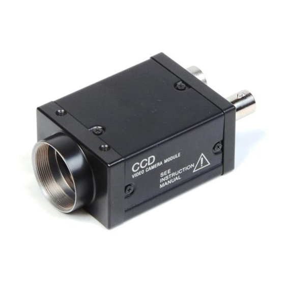
Sony XC-ST50 Technical Manual
B/w video camera module
Hide thumbs
Also See for XC-ST50:
- Specifications (4 pages) ,
- Service manual (92 pages) ,
- User manual (31 pages)

Related Manuals for Sony XC-ST50


Summary of Contents for Sony XC-ST50
- Page 1 CCD B/W VIDEO CAMERA MODULE XC-ST50/50CE XC-ST30/30CE Technical Manual (Ver. 1.0) — English —...
-
Page 2: Table Of Contents
RESTART RESET (R.R) ..................10 FRAME IMAGE OUTPUT WITH STROBE LIGHT ..........12 OUTPUT WAVEFORM TIMING CHART (XC-ST50 (EIA)/XC-ST30 (EIA)) ... 13 TIMING CHART OF EXTERNAL TRIGGER SHUTTER - MODE 1 ....... 17 TIMING CHART OF EXTERNAL TRIGGER SHUTTER - MODE 2 ....... 23 DIMENSIONS ...................... -
Page 3: Outline
XC-75 (installing a 1/2 type CCD) and the XC-73 (installing a 1/3 type CCD), which are used in various types of devices and systems and win popularity in the machine vision field. The XC-ST50/50CE and XC-ST30/30CE provides an external trigger shutter that can capture the image of a high-speed moving object using an external signal. -
Page 4: Specifications Comparison
XC-ST50/50CE XC-ST30/30CE SYSTEM CONFIGURATION The components making up the system based on XC-ST50/ST50CE or XC-ST30/ST30CE video camera are as follows. Camera cables Video camera module Camera adaptor CCXC-12P02N (2 m) XC-ST50/50CE DC-700/700CE CCXC-12P05N (5 m) XC-ST30/30CE CCXC-12P10N (10 m) CCXC-12P25N (25 m) -
Page 5: Main Specifications
Cell size Supply voltage +12 VDC (+10.5 V to 15V) XC-ST50: 8.4(H) x 9.8(V) um Power consumption XC-ST50/50CE: 2.0 W 8.6(H) x 8.3(V) um XC-ST50CE: XC-ST30/30CE: 1.9 W XC-ST30: 6.35(H) x7.4(V) um Operating temperature –5 ˚C to +45 ˚C... -
Page 6: Connection Diagram
2: A VS signal cannot be used simultaneously with an HD/VD signal. Junction box JB-77 Note : All functions of the XC-ST50/50CE and XC-ST30/30CE cannot (No trigger input terminal is provided.) be used when using DC-777/CE, DC-77RR/CE, and JB-77. Refer to the table shown below. -
Page 7: Location Of Parts And Operation
1 Lens mount section XC-ST30/30CE A commercial C-mount lens as well as a (XC-ST50 model) Sony standard lens can be used. 2 Camera mounting reference hole These screw holes are positioned with high precision related to CCD sensor. VIDEO CAMERA MODULE... -
Page 8: Phase Conditions Of External Synchronization
EXT-HD 455 (454) 455 (454) Unit: Clock 1 CLK = 69.84 n sec (XC-ST50/ST30) = 70.48 n sec (XC-ST50CE/ST30CE) The operation in parentheses refers to XC-ST50CE/ST30CE. Note : The synchronized VD signals are delayed for 1H at HD/VD external synchronization mode, while... -
Page 9: Electronic Shutter
XC-ST50/50CE XC-ST30/30CE ELECTRONIC SHUTTER Two types of electronic shutter are provided: normal shutter and external trigger shutter. The electronic shutter speed and type can be set using the DIP switch on the rear panel. DIP switch on the rear panel... -
Page 10: External Trigger Shutter
Set all DIP switches 1 to 4 on the rear panel to 0. An arbitrary shutter speed can be obtained by setting the trigger pulse width to the range of 2 µsec to 250 • msec. Exposure time = Trigger pulse width + 97 µsec (XC-ST50/ST30) Mode 1 Mode 2 Switch... - Page 11 The voltage and pulse width used are measured at pin 11 of the 12-pin multi-connector on the rear panel. Specifications of WEN (Write ENable Pulse) A: 5.0 V B: 0 V T: 15.875 ms (XC-ST50/30), 18.752 ms (XC-ST50CE/30CE) Output impedance: 10 kΩ or more...
-
Page 12: Restart Reset (R.r)
Continuous signal: 15.734 kHz (XC-ST50/ST30), 15.625 kHz (XC-ST50CE/30CE) Allowable frequency value ±1% EXT HD EXT VD VD interval(T): 262.5H or more (XC-ST50/ST30), 312.5H or more (XC-ST50CE/30CE) and 1 second or less (Recommended) Four or more VD pulses are required. Exposure time for Odd field... - Page 13 Continuous signal: 15.734 kHz (XC-ST50/ST30), 15.625 kHz (XC-ST50CE/30CE) Allowable frequency value ±1% EXT HD EXT VD VD interval(T): 262.5H or more (XC-ST50/ST30), 312.5H or more (XC-ST50CE/30CE) and 1 second or less (Recommended) Four or more VD pulses are required. 1/60 second...
-
Page 14: Frame Image Output With Strobe Light
Avoid lighting the scene during the light-emitting inhibit zone (see Note below). (The field is transfered to the storage area of the CCD, so it can be read out.) Note : For best performance, it is recommended not to use a flash between VD and VD + 10H (XC-ST50/ST30)/ 16H (XC-ST50CE/ST30CE). -
Page 15: Output Waveform Timing Chart (Xc-St50 (Eia)/Xc-St30 (Eia))
XC-ST50/50CE XC-ST30/30CE OUTPUT WAVEFORM TIMING CHART (XC-ST50 (EIA)/XC-ST30 (EIA)) Timing chart of horizontal output waveform 91 (6.36 µs) output signal Effective total pixel Dummy 69.8 ns pixel Optical black portion Horizontal transfer stop period Optical black portion Horizontal blanking period (11.0 µs) - Page 16 XC-ST50/50CE XC-ST30/30CE ELECTRONIC SHUTTER OUTPUT WAVEFORM TIMING CHART (XC-ST50 (EIA)/XC-ST30 (EIA)) Timing chart of vertical output waveform (2:1 interlaced field integration) Odd field (262.5 H) Even field (262.5 H) 253.5 H 253.5 H output signal 242.5 242.5 Empty Empty transfer...
- Page 17 XC-ST50/50CE XC-ST30/30CE OUTPUT WAVEFORM TIMING CHART (XC-ST50CE (CCIR)/XC-ST30CE (CCIR)) Timing chart of horizontal output waveform (6.91 µs) output signal Effective total pixel 752 Dummy 70.5 ns Optical black pixel portion Horizontal transfer stop period Optical black portion Horizontal blanking period (12.1 µs)
- Page 18 XC-ST50/50CE XC-ST30/30CE ELECTRONIC SHUTTER OUTPUT WAVEFORM TIMING CHART (XC-ST50CE (CCIR)/XC-ST30CE (CCIR)) Timing chart of vertical output waveform (2:1 interlaced field integration) Odd field (312.5 H) Even field (312.5 H) 7.5 H 305 H 7.5 H 305 H output signal 287.5 287.5...
-
Page 19: Timing Chart Of External Trigger Shutter - Mode 1
10 µs 1: This is a signal input from external equipment. Be sure to input both HD and VD signals in this case. Te = Trigger width + 97 µs (XC-ST50/30) 2: Exposure time Te Te = Trigger width + 120 µs (XC-ST50CE/30CE) (The trigger width should be between 2 µs and 1/4 s) - Page 20 1: This is a signal input from external equipment. Be sure to input both HD and VD signals in this case. The phase of the VD signal must coincide with the falling edge of the HD signal during input operation. Te = Trigger width + 97 µs (XC-ST50/ST30) 2: Exposure time Te Te = Trigger width + 120 µs (XC-ST50CE/ST30CE)
- Page 21 250H (XC-ST50/ST30) 293H (XC-ST50CE/ST30CE) 1: This is a signal input from external equipment. Te = Trigger width + 97 µs (XC-ST50/ST30) 2: Exposure time Te Te = Trigger width + 120 µs (XC-ST50CE/ST30CE) 3: Normal operation is engaged when the high period exceeds 1/3 sec. After that, the external trigger shutter operation is engaged when the trigger pulse goes “low”.
- Page 22 T : T = 10 ms or more T : T = 10 ms or more Video out 250H (XC-ST50/30) 250H (XC-ST50/30) 293H (XC-ST50CE/30CE) 293H (XC-ST50CE/30CE) 1: This is a signal input from external equipment. The period of a continuous VD signal is prescribed as one field.
- Page 23 XC-ST50/50CE XC-ST30/30CE TIMING CHART OF EXTERNAL TRIGGER SHUTTER - MODE 1 (NON-RESET MODE) For setting the shutter speed using DIP switch HD/VD input • Continuous HD input and single VD input Mode transition External input External trigger inhibition area shutter operation...
- Page 24 T : T = 10 ms or T : T = Under 10 ms T : T = 10 ms or more more Video out 250H (XC-ST50/30) 250H (XC-ST50/30) 293H (XC-ST50CE/30CE) 293H (XC-ST50CE/30CE) 1: This is a signal input from external equipment.
-
Page 25: Timing Chart Of External Trigger Shutter - Mode 2
+ 2H period or more. The trigger interval shorter than described above cannot be ensured. If a trigger pulse is not input under the prescribed conditions, please wait several V before re-entering a trigger pulse. Te = Trigger width + 97 µs (XC-ST50/ST30), 2: Exposure time Te Te = Trigger width + 120 µs (XC-ST50CE/ST30CE) - Page 26 XC-ST50/50CE XC-ST30/30CE TIMING CHART OF EXTERNAL TRIGGER SHUTTER - MODE 2 (RESET MODE) For setting the shutter speed using DIP switch Mode transition External input External trigger inhibition area shutter operation External trigger shutter operation Normal operation (50 ms) Trigger...
-
Page 27: Dimensions
XC-ST50/50CE XC-ST30/30CE DIMENSIONS XC-ST50/50CE XC-ST30/30CE (XC-ST50 model) 2-M3 deep 4 (Unit: mm) VIDEO CAMERA MODULE XC-ST50 57.5 65.5 4-M3 deep 4 50±0.5... -
Page 28: Spectral Response Characteristics (Typical Value)
XC-ST50/50CE XC-ST30/30CE SPECTRAL RESPONSE CHARACTERISTICS (TYPICAL VALUE) XC-ST50/ST30 1000 Wavelength (nm) COMPARISON OF SPECTRAL RESPONSE CHARACTERISTICS (TYPICAL VALUE) XC-75/73 and XC-ST50/ST30 XC-ST50/30 XC-75/73 (without IR cut filter) XC-75/73 (with IR cut filter) 1000 Wavelength (nm) -
Page 29: Various Lens Selection
XC-ST50/50CE XC-ST30/30CE VARIOUS LENS SELECTION The following shows the various lens specifications of the accessories available. XC-ST50/50CE and XC-ST30/30CE compatibility List of C-Mount Lenses Model name VLC-08YM VLC-12YM VLC-16Y-M VLC-25Y-M VLC-50Y-M Focal distance (mm) 1: 1.4 1: 1.8 1: 1.4 1: 1.6... - Page 30 Technical information contained herein is for reference only and does not convey any license by any implication or otherwise under any intellectual property right or other right of Sony or third parties. Sony cannot assume responsibility for any right infringements arising out of the use of this information.
- Page 31 4-14-1 Asahi-cho,Atsugi-shi, Kanagawa,243-0014 Japan Tel: +81-46-230-5873 Fax: +81-46-230-6243 U S A http://www.sony.com/videocameras Sony Electronics Inc. 1 Sony Drive Park Ridge, NJ 07656 Tel: +1-800-686-7669 Canada Sony of Canada Ltd. 115 Gordon Baker Rd, Toronto, Ontario M2H 3R6 Tel: +1-416-499-1414 Fax: +1-416-497-1774 Europe http://www.pro.sony-europe.com/ISP...