Table of Contents
DEALER NAME:
DEALER PHONE #:
MODEL #:
SERIAL #:
DATE INSTALLED:
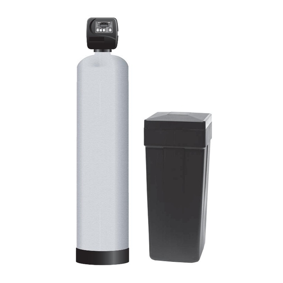
TTV Series
Softening Water System
Installation, Operation and
Maintenance Manual
CAUTION: Read and Follow all safety rules and
operating instructions before first use of product.
Aqua Treatment Service
194 Hempt Road
Mechanicsburg, PA 17050
www.aquat.com
Revised 01/17/13
Table of Contents

Related Manuals for ATS TTV1EEM-3T

Summary of Contents for ATS TTV1EEM-3T
-
Page 1: Maintenance Manual
TTV Series Softening Water System Installation, Operation and Maintenance Manual CAUTION: Read and Follow all safety rules and operating instructions before first use of product. DEALER NAME: Aqua Treatment Service DEALER PHONE #: 194 Hempt Road MODEL #: Mechanicsburg, PA 17050 www.aquat.com SERIAL #: DATE INSTALLED:... - Page 2 Aqua Treatment Service ©2013 • www.aquat.com...
-
Page 3: Table Of Contents
Table of Contents Installation Instructions: General ......................2 Installation Diagram ..................3 Control Valve: Front Cover and Drive Assembly ..............4 Regeneration and Error Screens, Button Operations and Functions ............5 User Displays ....................6 Configuration Settings ..................7 - 9 Setting Regeneration Cycle Times .............. -
Page 4: General
General Installation Instructions Pre Installation Check List — 4. Drain Line Connection Water Pressure A minimum of 30 psi is required for regenerated of the unit. If the water pressure is over 100 psi, a pressure reducing valve • Thread taped drain fitting into by-pass drainport. must be installed before the equipment and set at 85 psi •... -
Page 5: Installation Diagram
Installation Diagram Direction of water flow Sanitary Sewer Line Hard Water Line to Unsoftened Fixtures Cold Water Outlet Cold Water Inlet Valve Control System Drain Line Brine Tank Line To approved air gap drain. Clean Water Tank Assembly Brine Tank Assembly Brine Tank Overflow Drain Line: .5”... -
Page 6: Control Valve
Control Valve EE Front Cover and Drive Assembly Drawing No. Order No. Description Quantity V3175EE-01 WS1EE FRONT COVER ASSEMBLY V3107-01 WS1 MOTOR V3106-01 WS1 DRIVE BRACKET & SPRING CLIP V3408EE-02BOARD WS1THRU2L EEPCBRD MAV/ALT REPL V3110 WS1 DRIVE GEAR 12X36 V3109 WS1 DRIVE GEAR COVER V3186 WS1 AC ADAPTER 110V-12V... -
Page 7: Regeneration And Error Screens
Control Valve cont: Regeneration and Error Screens Regen Screen Displays the time remaining in the current cycle. Pressing REGEN advances to the next cycle. Error Screen seconds. Clear by dissconnecting the power supply at the PC board and reconneting, or press the NEXT and Button Operation and Function Scrolls to the next display. -
Page 8: User Displays
Control Valve cont: User Displays General Operation When the system is operating, one of À ve displays may be shown. Pressing NEXT will alternate between the displays shown below. User 1 Typical user display. If volume is selected in ConÀ guration Settings Step 3CS, shows volume remaining to regeneration. -
Page 9: Configuration Settings
Control Valve cont: ConÀ guration Settings Press V and W buttons simultaneously for 5 seconds and release. If screen in Step 2CS does not Step 1CS – Step 1CS appear, the lock on the valve is activated. To unlock press W, NEXT, REGEN, V in sequence, then press V and W buttons simultaneously for 5 seconds and release. - Page 10 Control Valve cont: Step 5CS – - Allows selection of one of the following Step 5CS using the V or W buttons: • the Control Valve to have no hard water bypass; • the Control Valve to act as an alternator; or Volume Volume •...
- Page 11 Control Valve cont: Step 6CS Step 6CS – Set duration of the special rinse cycle to be performed prior to a valve returning to Service. Selectable from 1 - 20 minutes or OFF. Volume Only viewed if 2.0 is set in 2CS, and ALTA or ALTb is set in 5CS. Press NEXT to go to Step 7CS.
-
Page 12: Setting Regeneration Cycle Times
Control Valve cont: Setting Regeneration Cycle Times Step 1CT - Press NEXT and simultaneously for 5 seconds and release. Step 1CT If screen in Step 2CT does not appear, the lock on the valve is activated. To unlock press , NEXT, REGEN, in sequence, then press NEXT and simultaneously for 5 seconds and release. -
Page 13: Installer Display Settings
Control Valve cont: Installer Display Settings One of three sets of displays will be shown depending on what was selected in ConÀ guration Settings Step 3CS. Volume (Gallons) selected in ConÀ guration Settings Step 3CS Step 1I - Step 1I To enter Installer Display press the NEXT and V buttons simultaneously for 5 seconds and release. - Page 14 Control Valve cont: 7 Day or 7/ Volume (Gallons) selected in ConÀ guration Settings Step 3CS Step 1I - To enter Installer Display press the NEXT and Step 1I V buttons simultaneously for 5 seconds and release. Use V or W buttons to set the current day of Step 2I - Step 2I the week...
-
Page 15: Diagnostics
Control Valve cont: Diagnostics V and W Step 1D - Press buttons simultaneously for Step 1D V and W 5 seconds and release. Then press buttons simultaneously for 2 seconds and release. If screen in Step 2D does not appear the lock on the valve is activated. -
Page 16: Parts Breakdown
Parts Breakdown Aqua Treatment Service ©2013 • www.aquat.com... -
Page 17: Control Valve
Parts Breakdown cont: Aqua Treatment Service ©2013 • www.aquat.com... - Page 18 Parts Breakdown cont: WS1 Drive Cap Assembly, Downfl ow Piston, Upfl ow Piston, Regenerant Piston and Spacer Stack Assembly Drawing No. Order No. Description Quantity V3005 WS1 Spacer Stack Assembly V3004 Drive Cap ASY Refer to Programming and Back Plate Cover Drawing Manual V3011* WS1 Piston Downfl...
- Page 19 Parts Breakdown cont: Aqua Treatment Service ©2013 • www.aquat.com...
- Page 20 Parts Breakdown cont: Refi ll Flow Control Assembly and Refi ll Port Plug Drawing No. Order No. Description Quantity This part is required for backwash only V3195-01 WS1 Refi ll Port Plug Asy systems H4615 Elbow Locking Clip JCP-P-6 Polytube insert 3/8” JCPG-6PBLK Nut 3/8”...
- Page 21 Parts Breakdown cont: Drain Line – 3/4” Drawing No. Order No. Description Quantity H4615 Elbow Locking Clip PKP10TS8-BULK Polytube insert 5/8 Option V3192 WS1 Nut ¾ Drain Elbow Option V3158-01 WS1 Drain Elbow ¾ Male V3163 O-ring 019 V3159-01 WS1 DLFC Retainer ASY V3162-007 WS1 DLFC 0.7 gpm for ¾...
- Page 22 Parts Breakdown cont: Aqua Treatment Service ©2013 • www.aquat.com...
- Page 23 Parts Breakdown cont: Installation Fitting Assemblies Order No: V3007 Order No: V3007-01 Description: WS1 Fitting 1” PVC Male NPT Elbow Assembly Description: WS1 Fitting ¾” & 1” PVC Solvent 90° ASY Drawing No. Order No. Description Quantity Order Drawing No. Description Quantity V3151...
-
Page 24: Installation Fitting Assemblies
Parts Breakdown cont: Installation Fitting Assemblies Order No: V3007-06 Order No. V3007-07 Description: WS1 Fitting 1” Plastic Male BSPT Assembly Description: WS1 Fitting 1¼” & 1½” PVC Solvent Assembly Drawing No. Order No. Description Quantity Drawing No. Order No. Description Quantity V3151 WS1 Nut 1”... - Page 25 Parts Breakdown cont: Bypass Valve Drawing No. Order No. Description Quantity V3151 WS1 Nut 1” Quick Connect V3150 WS1 Split Ring V3105 O-Ring 215 V3145 WS1 Bypass 1” Rotor V3146 WS1 Bypass Cap V3147 WS1 Bypass Handle V3148 WS1 Bypass Rotor Seal Retainer V3152 O-ring 135 V3155...
-
Page 26: Specifications
Specifications 1” 10” x 40” 20,000 32,000 TTV1EEM-3T 1” 10” x 54” 30,000 48,000 TTV1EEM-5T H1071-02 …………………………… SALT GRID Floor Dimensions 33” NOTES: Overall Depth of Unit: 24” All Dimensions are of the Unit only. Size will very depending on plumbing used for installation of the system. -
Page 27: Troubleshooting
Troubleshooting Troubleshooting TC control valves do not have meters so shaded ares are not applicable for TC control valves Problem Possible Cause Solution a. No power at electric outlet a. Repair outlet or use working outlet b. Control valve Power Adapter not plugged into b. - Page 28 Troubleshooting cont: Problem Possible Cause Solution a. Bypass valve is open or faulty a. Fully close bypass valve or replace b. Media is exhausted due to high water usage b. Check program settings or diagnostics for abnormal water usage c. Meter not registering c.
- Page 29 Troubleshooting cont: Problem Possible Cause Solution a. Power outage during regeneration a. Upon power being restored control will fi nish the remaining regeneration time. Reset time of day. b. Damaged seal/ stack assembly b. Replace seal/ stack assembly 13. Water running to drain c.
- Page 30 Troubleshooting cont: Problem Possible Cause Solution a. Motor failure during a regeneration a. Check motor connections then Press NEXT and REGEN buttons for 3 seconds to resynchronize software with piston position or disconnect power supply from PC Board for 5 seconds and then reconnect.
-
Page 31: Warranty
The customer must order ATS replacement parts if required as a standard purchase until the defective part is received and evaluated by the factory. ATS will inspect, test, and determine the cause of defective components or parts. ATS at its sole discretion will make necessary repairs to or replace components.