Table of Contents
Quick Links
Wireless P-T-P Ethernet Extender Quick Start Guide
Extend Ethernet links between buildings wirelessly
and with ease.
Provides affordable point-to-point wireless Ethernet extension up to 6.2 miles
(10 km).
Order toll-free in the U.S.: Call 877-877-BBOX (outside U.S. call 724-746-5500)
Customer
FREE technical support 24 hours a day, 7 days a week: Call 724-746-5500 or fax 724-746-0746
Support
Mailing address: Black Box Corporation, 1000 Park Drive, Lawrence, PA 15055-1018
Information
Web site: www.blackbox.com • E-mail: [email protected]
LWE100A
LWE100A-KIT
LWE100AE
LWE100AE-KIT
LWE100AU
BLACK BOX
LWE100A-W1
LWE100A-W3
LWE100A-W1-KIT
LWE100A-W3-KIT
LWE100AU-KIT
®
Table of Contents

Related Manuals for Black Box LWE100A


Summary of Contents for Black Box LWE100A
-
Page 1: Black Box
Order toll-free in the U.S.: Call 877-877-BBOX (outside U.S. call 724-746-5500) Customer FREE technical support 24 hours a day, 7 days a week: Call 724-746-5500 or fax 724-746-0746 Support Mailing address: Black Box Corporation, 1000 Park Drive, Lawrence, PA 15055-1018 Information Web site: www.blackbox.com • E-mail: [email protected]... -
Page 2: Related Documentation
Trademarks Used in this Manual Trademarks Used in this Manual Black Box and the Double Diamond logo are registered trademarks of BB Technologies, Inc. Any other trademarks mentioned in this manual are acknowledged to be the property of the trademark owners. -
Page 3: Table Of Contents
Table of Contents Table of Contents 1. Introduction ................................4 2. Preparing for Installation ..............................4 Professional Installation Required ..........................4 2.2 Safety Precautions ...............................4 2.3 Installation Precautions ..............................5 2.4 What’s Included ................................5 2.5 Component Descriptions .............................5 System Installation ................................8 3.1 Installation Steps ................................8 3.2 Using the External Antenna ............................ -
Page 4: Introduction
Password: password NOTE: If the units are factory defaulted, they will no longer retain the wireless bridge configuration and will need to be reconfigured. Contact Black Box Technical Support at 724-746-5500 or [email protected] for assistance. LWE100A See the rest of this quick start guide for information about installing and configuring the unit as an access point (AP), customer premises equipment (CPE), wireless distribution system (WDS), or AP repeater. -
Page 5: Installation Precautions
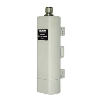
• This Quick Installation Guide NOTE: You can access the user manual at ftp://ftp.blackbox.com/anonymous/manuals/L/LWE100A_rev2_user.pdf. 2.5 Component Descriptions Figure 2-1 shows the LWE100A. Figure 2-2 illustrates the pole mounting ring, and Figure 2-3 shows the power cord and PoE injector. Page 5... - Page 6 Chapter 2: Preparing for Installation Figure 2-1. LWE100A Ethernet extender. Figure 2-2. Pole-mounting ring. 724-746-5500 | blackbox.com Page 6...
- Page 7 Chapter 2: Preparing for Installation Figure 2-3. Power cord and PoE injector. WARNING: Users MUST use the power cord and PoE injector shipped in the box with the Wireless P-T-P Ethernet Extender. Using other options will damage the extender. Page 7...
-
Page 8: System Installation
Chapter 3: System Installation 3. System Installation 3.1 Installation Steps 1. On the bottom of the Wireless P-T-P Ethernet Extender is a removable cover. Grab the cover and pull it back gently to remove it as shown in Figure 3-1. Figure 3-1. - Page 9 Chapter 3: System Installation Figure 3-3. Replacing the cover. 4. Take out the power cord and PoE injector, and plug the power cord into the DC port of the PoE injector. 5. Connect what you assembled in Steps 3 and 4 together by plugging the other side of the Ethernet cable from Step 3 into the PoE port of the PoE injector in Step 4.
- Page 10 Chapter 3: System Installation Figure 3-4. Unlocking the pole-mounting ring. 7. Mount the Wireless P-T-P Ethernet Extender securely to the pole by locking the pole mounting ring tightly. Figure 3-5. Mounting the extender to a pole. 724-746-5500 | blackbox.com Page 10...
- Page 11 Chapter 3: System Installation 8. When installation is complete, the extender should look like Figure 3-6. Figure 3-6. Extender installed outdoors on a pole. Page 11...
-
Page 12: Using The External Antenna
Chapter 3: System Installation 3.2 Using the External Antenna If you prefer to use the external antenna with N-type connector for your application instead of the built-in directional antenna, follow the steps below. 1. Grab the black rubber on the top of the Wireless P-T-P Ethernet Extender, and slightly pull it up as shown in Figure 3-7. The metal N-type connector will appear. -
Page 13: Using The Grounding Wire
Chapter 3: System Installation 3.3 Using the Grounding Wire The Wireless P-T-P Ethernet Extender is shipped with a grounding wire. Properly ground the unit to protect against power surges. 1. Loosen and remove the metal O-ring on the N-type antenna connector. 2. -
Page 14: Configuration Steps
Chapter 4: Configuration Steps 4. Configuration Steps Connect the Wireless P-T-P Ethernet Extender to your PC by plugging in an Ethernet cable to the PoE injector’s LAN port on one side and into the PC’s LAN port on the other side. Power on the Wireless P-T-P Ethernet Extender using PoE from the PoE injector. 1. -
Page 15: Ap Mode
Chapter 4: Configuration Steps 3. Next, you will see the extender’s log-in page. The default name and password are “admin” and “password,” respectively. Enter them and then click “Login.” NOTE: Preconfigured units will have the same default name and password: default name: admin and default password: password. -
Page 16: Wireless Client Mode
Chapter 4: Configuration Steps Figure 4-4. Wireless Basic Settings screen. 2. If security is required, click “Profile Settings” and enter “VAP Profile 1 Settings” as shown in Figure 4-5. For better security, set the “Network Authentication” and “Data Encryption.” Click “Apply” to save the parameters. Figure 4-5. - Page 17 Chapter 4: Configuration Steps Figure 4-6. Wireless Basic Settings screen. 2. Click the “Site Survey” button beside Wireless Mode. (See Figure 4-6.) The switch will scan all the available access points within its coverage. Select the one you prefer to connect to, and click “Select” to establish the connection. (See Figure 4-7.) Figure 4-7.
-
Page 18: Bridge Mode
Chapter 4: Configuration Steps Figure 4-8. Wireless Profile Settings screen. 4.3 Bridge Mode 1. Choose “Wireless > Basic Settings.” Then you will see the “Wireless Basic Settings” page asin Figure 4-9. Choose “Bridge” for Wireless Mode, and click “Apply” to save it. To optimize your application, change the other parameters before clicking “Apply.”... - Page 19 Chapter 4: Configuration Steps 2. Click “WDS Settings” in the left column, type the MAC address of the remote bridge into the “Remote AP MAC Address 1” field and click “Apply.” See Figure 4-10. Figure 4-10. WDS Settings screen. NOTE: Bridge mode uses the WDS protocol that is not defined as the standard, so you might experience compatibility issues between equipment from different vendors.
-
Page 20: Ap Repeater Mode
Chapter 4: Configuration Steps Figure 4-11. Antenna Alignment screen. 4.4 AP Repeater Mode 1. Choose “Wireless > Basic Settings” (see Figure 4-12). Choose “AP Repeater” from Wireless Mode, and click “Apply” to save it. To optimize your application, change the other parameters before clicking “Apply.” NOTE: For longer transmission of the Wireless P-T-P Ethernet Extender, you may also use an external antenna;... - Page 21 Chapter 4: Configuration Steps 2. To establish a point-to-point bridge connection, follow the procedures described in Section 4.3: Bridge Mode. To connect the wireless client to the AP, follow the procedures described in Wireless Client mode. You have primarily completed configuration of the Wireless P-T-P Ethernet Extender and it’s ready to operate. For more advanced configurations, refer to the user manual.
- Page 22 NOTES 724-746-5500 | blackbox.com Page 22...
- Page 23 NOTES Page 23...
- Page 24 About Black Box Black Box provides an extensive range of networking and infrastructure products. You’ll find everything from cabinets and racks and power and surge protection products to media converters and Ethernet switches all supported by free, live 24/7 Tech support available in 30 seconds or less.