Dell PowerVault MD3060e Owner's Manual
Storage enclosure
Hide thumbs
Also See for PowerVault MD3060e:
- Installation and configuration manual (63 pages) ,
- Administrator's manual (48 pages) ,
- Hardware and software manual (25 pages)
Table of Contents
Quick Links
See also:
Administrator's Manual, Cli Manual
Table of Contents
Troubleshooting

Related Manuals for Dell PowerVault MD3060e


Summary of Contents for Dell PowerVault MD3060e
- Page 1 Dell PowerVault MD3060e Storage Enclosure Owner's Manual Regulatory Model: E08J Series Regulatory Type: E08J001...
- Page 2 WARNING: A WARNING indicates a potential for property damage, personal injury, or death. Copyright © 2014 Dell Inc. All rights reserved. This product is protected by U.S. and international copyright and intellectual property laws. Dell and the Dell logo are trademarks of Dell Inc.
-
Page 3: Table Of Contents
Contents 1 About your system....................5 ............................5 Introduction ..........................5 Front-Panel Features ......................... 6 Front-Panel Indicators ..........................8 Back-Panel Features ...................9 Cooling Fan Module LED Indicator Codes ................10 Power Supply Module Features And Indicators ....................11 Physical Disk Installation Guidelines ......................12 Enclosure Management Module ......... - Page 4 ...................34 Troubleshooting Power Supply Modules ................. 35 Troubleshooting Enclosure Cooling Problems ......................35 Troubleshooting Physical Disks ..................36 Troubleshooting A Wet Storage Enclosure 4 Technical Specifications..................37 5 Getting help......................40 .......................40 Locating your system service tag ........................... 40 Contacting Dell ........................40 Documentation feedback...
-
Page 5: About Your System
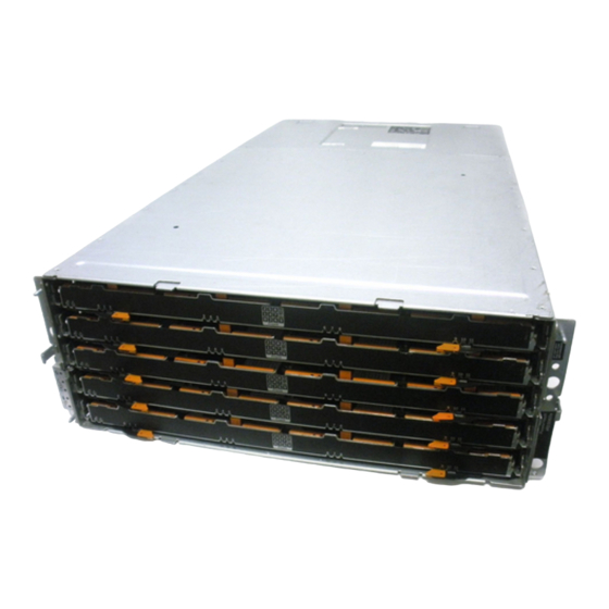
The MD3060e storage enclosure is a 4U rack-mounted system, capable of accommodating up to sixty 3.5 inch or 2.5 inch physical disks. This document familiarizes you with the functions of the Dell PowerVault MD3060e storage enclosure. The document is organized according to the tasks that you must complete after receiving your storage enclosure. -
Page 6: Front-Panel Indicators
Front-Panel Indicators Figure 2. Front-Bezel Indicators Figure 3. Front-Panel Indicators... - Page 7 Item Indicator Icon Description Power-on indicator The power-on indicator lights green when at least one power supply module is supplying power to the storage enclosure. Standby power indicator The standby power indicator lights green when the system is in standby mode and the main power is off.
-
Page 8: Back-Panel Features
Item Indicator Icon Description Drive activity indicator NOTE: The associated physical disk is indicated by a number (0 to 11) that is displayed above the drive activity indicator. For example, for physical disk 2 on the physical disk drawer, the drive activity indicator has 2 displayed above the drive activity indicator. -
Page 9: Cooling Fan Module Led Indicator Codes
Cooling Fan Module LED Indicator Codes Figure 5. Cooling Fan Module Indicators Item Indicator Icon Description Power indicator The power indicator lights green when power to the cooling fan module is available. Service action required The Service action required indicator lights amber indicator when there is a fault in the cooling fan module. -
Page 10: Power Supply Module Features And Indicators
Power Supply Module Features And Indicators NOTE: Your storage enclosure is shipped with two IEC C19 to C20 jumper cords. Connect the C19 plug to the enclosure’s power supplies and the C20 plug to the power distribution unit (PDU) in the rack cabinet. -
Page 11: Physical Disk Installation Guidelines
Item Indicator or Connector Icon Description Indicates that you cannot remove the power supply module from the system. Service action required The service action required indicator lights amber indicator when there is a fault in the power supply module. AC power indicator Green Indicates that AC output voltage is within the limit. -
Page 12: Enclosure Management Module
The MD3060e storage enclosure supports mixing of physical disk types. NOTE: 3.5" 10k and 15k RPM SAS drives are not supported. For the latest drive support, refer to Dell PowerVault MD3060e Support Matrix at: dell.com/powervaultmanuals. Enclosure Management Module Use the enclosure management modules to expand the storage capacity, by daisy-chaining your storage enclosure with additional MD3060e storage enclosures. -
Page 13: Storage Enclosure Thermal Shutdown
SAS IN port 1 For SAS connection of the storage enclosure to a server, RAID controller, or another storage enclosure. Serial debug port Dell support only. Telnet port Dell support only. SAS OUT port For connection to additional storage enclosures. - Page 14 Dell PowerVault MD3060e Support Matrix — Provides information about the software and hardware compatibility matrices for the storage enclosure. • For the full name of an abbreviation or acronym used in this document, see the Dell Glossary – Version 2 Glossary at dell.com/support/manuals. •...
-
Page 15: Installing And Removing System Components
Installing and removing system components Recommended Tools You may need the following items to perform the procedures in this section: • #2 Phillips screwdriver • T8 and T15 Torx screwdrivers • Wrist grounding strap connected to ground Removing And Installing The Front Bezel Installing The Front Bezel You must install the front bezel on the system to secure the disk drawers against accidental removal. -
Page 16: Removing The Front Bezel
Figure 9. Removing and Installing the Front Bezel release latches (2) front bezel guide pins (4) Removing The Front Bezel You must remove the front bezel to access the disk drawers, which enables you to remove and install physical disks in the system. Press the release latch on either side of the front bezel. -
Page 17: Opening The Physical-Disk Drawer
Damage due to servicing that is not authorized by Dell is not covered by your warranty. Read and follow the safety instructions that came with the product. -
Page 18: Closing The Physical-Disk Drawer
Damage due to servicing that is not authorized by Dell is not covered by your warranty. Read and follow the safety instructions that came with the product. -
Page 19: Removing The Physical-Disk Drawer
Damage due to servicing that is not authorized by Dell is not covered by your warranty. Read and follow the safety instructions that came with the product. -
Page 20: Installing The Physical-Disk Drawer
Damage due to servicing that is not authorized by Dell is not covered by your warranty. Read and follow the safety instructions that came with the product. -
Page 21: Physical Disks
Damage due to servicing that is not authorized by Dell is not covered by your warranty. Read and follow the safety instructions that came with the product. - Page 22 Figure 13. Removing and Installing the 2.5 Inch Physical Disk in a 2.5 Inch Physical-Disk Carrier 2.5 inch physical drive cage guide pins (4) release handle holes on physical disk (4) carrier for 2.5 inch physical disk 2.5 inch physical disk...
-
Page 23: Installing A Physical Disk In A Physical-Disk Carrier
Damage due to servicing that is not authorized by Dell is not covered by your warranty. Read and follow the safety instructions that came with the product. -
Page 24: Removing A Physical Disk From A Physical-Disk Drawer
Damage due to servicing that is not authorized by Dell is not covered by your warranty. Read and follow the safety instructions that came with the product. -
Page 25: Installing A Physical Disk In A Physical-Disk Drawer
Damage due to servicing that is not authorized by Dell is not covered by your warranty. Read and follow the safety instructions that came with the product. -
Page 26: Removing The Sas Chain Cable(S)
Damage due to servicing that is not authorized by Dell is not covered by your warranty. Read and follow the safety instructions that came with the product. -
Page 27: Installing The Sas Chain Cable(S)
Damage due to servicing that is not authorized by Dell is not covered by your warranty. Read and follow the safety instructions that came with the product. -
Page 28: Enclosure Management Modules
Damage due to servicing that is not authorized by Dell is not covered by your warranty. Read and follow the safety instructions that came with the product. -
Page 29: Installing An Enclosure Management Module
Damage due to servicing that is not authorized by Dell is not covered by your warranty. Read and follow the safety instructions that came with the product. -
Page 30: Removing A Power Supply Module
Damage due to servicing that is not authorized by Dell is not covered by your warranty. Read and follow the safety instructions that came with the product. -
Page 31: Installing A Power Supply Module
Damage due to servicing that is not authorized by Dell is not covered by your warranty. Read and follow the safety instructions that came with the product. -
Page 32: Cooling Fan Modules
Damage due to servicing that is not authorized by Dell is not covered by your warranty. Read and follow the safety instructions that came with the product. -
Page 33: Installing A Cooling Fan Module
Damage due to servicing that is not authorized by Dell is not covered by your warranty. Read and follow the safety instructions that came with the product. -
Page 34: Troubleshooting Your System
Damage due to servicing that is not authorized by Dell is not covered by your warranty. Read and follow the safety instructions that came with the product. -
Page 35: Troubleshooting Enclosure Cooling Problems
Damage due to servicing that is not authorized by Dell is not covered by your warranty. Read and follow the safety instructions that came with the product. -
Page 36: Troubleshooting A Wet Storage Enclosure
Damage due to servicing that is not authorized by Dell is not covered by your warranty. Read and follow the safety instructions that came with the product. -
Page 37: Technical Specifications
MD3060e Storage Enclosure Support Matrix. Enclosure Management Modules Dell PowerVault MD3060e storage enclosures Supports 60 physical disks Redundant path connectivity provides redundant data paths to each hard drive SAS connectors... - Page 38 1 °C/300 m (1 °F per 550 ft) above 900 m (2952.75 ft). NOTE: For information on supported expanded operating temperature range and configurations, see the Owner's Manual at dell.com/support/ manuals. Storage –40 °C to 65 °C (–40 °F to 149 °F) with a maximum temperature gradation of 20 °C per hour...
- Page 39 Environmental Altitude Operating Maximum 3000 m (9,842 ft) Storage Maximum 12192 m (40,000 ft) Airborne contaminant level Class G1 as defined by ISA-S71.04-1985...
-
Page 40: Getting Help
Code and Service Tag are found on the front of a physical DR Series system by pulling out the information tag. This can also be found on the support tab in the GUI. This information is used by Dell to route support calls to the appropriate personnel.