Table of Contents
Quick Links
VES1724-56
24-port Temperature-Hardened VDSL2 Box DSLAM
Default Login Details
IP Address
https://192.168.1.1
User Name
Password
Version 3.80
Edition 1, 1/2012
www.zyxel.com
www.zyxel.com
admin
1234
IMPORTANT!
READ CAREFULLY
BEFORE USE.
KEEP THIS GUIDE
FOR FUTURE
REFERENCE.
Copyright © 2012
ZyXEL Communications Corporation
Table of Contents

Related Manuals for ZyXEL Communications VES1724-56


Summary of Contents for ZyXEL Communications VES1724-56
- Page 1 24-port Temperature-Hardened VDSL2 Box DSLAM Default Login Details IMPORTANT! IP Address https://192.168.1.1 READ CAREFULLY User Name admin BEFORE USE. Password 1234 KEEP THIS GUIDE FOR FUTURE REFERENCE. Version 3.80 Edition 1, 1/2012 www.zyxel.com www.zyxel.com Copyright © 2012 ZyXEL Communications Corporation...
- Page 2 Note: It is recommended you use the Web Configurator to configure the Switch. • Web Configurator Online Help Click the help icon in any screen for help in configuring that screen and supplementary information. • Support Disc Refer to the included CD for support documents. VES1724-56 User’s Guide...
-
Page 3: Table Of Contents
Multicast ...........................217 Authentication and Accounting ....................233 IP Source Guard ........................246 Loop Guard ..........................267 CFM ............................271 VLAN Mapping .........................275 Layer 2 Protocol Tunneling ......................279 DoS Prevention ........................283 PPPoE IA ..........................285 SFP Threshold .........................291 Static Route ..........................295 Differentiated Services ......................298 VES1724-56 User’s Guide... - Page 4 Contents Overview DHCP ............................305 Maintenance ..........................313 Access Control .........................320 Diagnostic ..........................341 Syslog ............................342 Loop Diagnostic ........................345 MAC Table ..........................349 ARP Table ..........................351 Hardware Information .......................353 CFM Action ..........................354 IPv6 Cache ..........................356 Troubleshooting ........................363 Product Specifications ......................367 VES1724-56 User’s Guide...
-
Page 5: Table Of Contents
3.1 Front Panel ..........................27 3.1.1 Power Connector ......................27 3.1.2 Gigabit Ethernet Ports ....................28 3.1.3 Mini-GBIC Slots ......................29 3.1.4 Management Port .......................30 3.1.5 Console Port .......................31 3.1.6 ALARM Slot ........................31 3.2 LEDs ...........................32 Chapter 4 The Web Configurator ......................35 VES1724-56 User’s Guide... - Page 6 7.1 Overview ..........................55 7.2 Port Status Summary ......................55 7.2.1 VDSL Port Status Change ..................56 7.2.2 VDSL Port Details .......................57 7.2.3 VDSL Summary ......................67 7.2.4 VTUR Counter ......................68 7.2.5 Port Details .........................70 Chapter 8 Basic Setting .......................... 73 VES1724-56 User’s Guide...
- Page 7 9.3.6 VDSL Line Profile Setup > Virtual Noise ..............117 9.3.7 VDSL Channel Profile Setup ..................118 9.3.8 VDSL G.INP Setup ....................120 9.3.9 VDSL INM Profile Setup ...................121 9.4 VDSL Alarm Template Setup .....................123 9.4.1 VDSL Line Alarm Profile Setup ................124 VES1724-56 User’s Guide...
- Page 8 ................152 Chapter 12 Static Multicast Forward Setup ................... 154 12.1 Static Multicast Forwarding Overview ................154 12.2 Configuring Static Multicast Forwarding ................155 Chapter 13 Filtering..........................158 13.1 Configure a Filtering Rule .....................158 Chapter 14 Spanning Tree Protocol......................160 VES1724-56 User’s Guide...
- Page 9 Port Authentication ......................186 18.1 Port Authentication Overview ..................186 18.1.1 IEEE 802.1x Authentication ..................186 18.1.2 MAC Authentication ....................187 18.2 Port Authentication Configuration ..................188 18.2.1 Activate IEEE 802.1x Security ................188 18.2.2 Activate MAC Authentication .................189 Chapter 19 MAC Limit ..........................191 VES1724-56 User’s Guide...
- Page 10 23.2 VLAN Stacking Port Roles ....................209 23.3 VLAN Tag Format ......................210 23.3.1 Frame Format ......................210 23.4 Configuring VLAN Stacking ....................211 23.4.1 Port-based Q-in-Q ....................212 23.4.2 Selective Q-in-Q ....................214 23.4.3 Port-based InnerQ ....................215 Chapter 24 Multicast ..........................217 24.1 Multicast Overview ......................217 VES1724-56 User’s Guide...
- Page 11 26.1.1 DHCP Snooping Overview ..................246 26.1.2 ARP Inspection Overview ..................248 26.2 IP Source Guard ......................250 26.3 IP Source Guard Static Binding ..................250 26.4 DHCP Snooping .......................252 26.5 DHCP Snooping Configure ....................254 26.5.1 DHCP Snooping Port Configure ................256 VES1724-56 User’s Guide...
- Page 12 DoS Prevention ........................283 31.1 DoS Prevention Overview ....................283 31.2 Configuring DoS Prevention .....................283 Chapter 32 PPPoE IA ..........................285 32.1 PPPoE Intermediate Agent Overview ................285 32.1.1 PPPoE Intermediate Agent Tag Format ..............285 32.1.2 Sub-Option Format ....................286 VES1724-56 User’s Guide...
- Page 13 36.3.2 DHCP Relay Agent Information Format ..............306 36.3.3 Sub-Option Format ....................307 36.3.4 Configuring DHCP Global Relay ................307 36.3.5 Global DHCP Relay Configuration Example ............309 36.4 Configuring DHCP VLAN Settings ................310 36.4.1 Example: DHCP Relay for Two VLANs ..............311 VES1724-56 User’s Guide...
- Page 14 38.8.1 Internet Explorer Warning Messages ..............332 38.8.2 Mozilla Firefox Warning Messages .................335 38.8.3 Netscape Navigator Warning Messages ..............336 38.8.4 The Main Screen ....................337 38.9 Service Port Access Control ..................338 38.10 Remote Management ....................339 Chapter 39 Diagnostic ..........................341 39.1 Diagnostic ........................341 VES1724-56 User’s Guide...
- Page 15 46.2 Neighbor Cache .......................357 46.3 Prefix List .........................358 46.4 Destination Cache ......................359 46.5 Route List ........................360 46.6 Default Router List ......................361 Chapter 47 Troubleshooting........................363 47.1 Power, Hardware Connections, and LEDs ...............363 47.2 Switch Access and Login ....................364 VES1724-56 User’s Guide...
- Page 16 Table of Contents 47.3 Switch Configuration ......................366 Chapter 48 Product Specifications ......................367 Appendix A Common Services .................... 383 Appendix B Legal Information....................387 Index ............................389 VES1724-56 User’s Guide...
-
Page 17: User's Guide
User’s Guide... -
Page 19: Getting To Know Your Switch
1.2.1 MTU Application The following diagram depicts a typical application of the switch with the VDSL modems, in a large residential building, or multiple tenant unit (MTU), that leverages existing phone line wiring to VES1724-56 User’s Guide... -
Page 20: Curbside Application
1.2.2 Curbside Application The switch can also be used by an Internet Service Provider (ISP) in a street cabinet to form a “mini POP (Point-of-Presence)” to provide broadband services to residential areas that are too far away VES1724-56 User’s Guide... -
Page 21: Ways To Manage The Switch
Switch to its factory default settings. If you backed up an earlier configuration file, you would not have to totally re-configure the Switch. You could simply restore your last configuration. VES1724-56 User’s Guide... - Page 22 Chapter 1 Getting to Know Your Switch VES1724-56 User’s Guide...
-
Page 23: Hardware Installation And Connection
Remove the adhesive backing from the rubber feet. Attach the rubber feet to each corner on the bottom of the Switch. These rubber feet help protect the Switch from shock or vibration and ensure space between devices when stacking. Figure 3 Attaching Rubber Feet VES1724-56 User’s Guide... -
Page 24: Mounting The Switch On A Rack
Using a #2 Philips screwdriver, install the M3 flat head screws through the mounting bracket holes into the Switch. Repeat steps to install the second mounting bracket on the other side of the Switch. You may now mount the Switch on a rack. Proceed to the next section. VES1724-56 User’s Guide... -
Page 25: Mounting The Switch On A Rack
Connect the frame ground on the rear panel to a building’s protective earthing terminals. Use a 18 AWG or larger green-and-yellow frame ground wire. Connect the frame ground before you connect any other cables or wiring. Figure 6 Frame Ground Frame Ground VES1724-56 User’s Guide... - Page 26 Chapter 2 Hardware Installation and Connection VES1724-56 User’s Guide...
-
Page 27: Hardware Overview
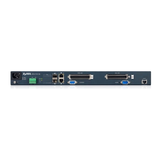
Connect to a computer using an RJ-45 Ethernet cable for local configuration of the Switch. CONSOLE The console port is for local configuration of the Switch. ALARM This port is for alarm. 3.1.1 Power Connector Note: Make sure you are using the correct power source as shown on the panel. VES1724-56 User’s Guide... -
Page 28: Gigabit Ethernet Ports
Ethernet port are the same in order to connect. 3.1.2.1 Default Ethernet Negotiation Settings The factory default negotiation settings for the Gigabit ports on the Switch are: • Speed: Auto • Duplex: Auto • Flow control: Off • Link Aggregation: Disabled VES1724-56 User’s Guide... -
Page 29: Mini-Gbic Slots
Insert the transceiver into the slot with the exposed section of PCB board facing down. Press the transceiver firmly until it clicks into place. The Switch automatically detects the installed transceiver. Check the LEDs to verify that it is functioning properly. Close the transceiver’s latch (latch styles vary). VES1724-56 User’s Guide... -
Page 30: Management Port
Figure 12 Transceiver Removal Example 3.1.4 Management Port The MGMT (management) port is used for local management. Connect directly to this port using an Ethernet cable. You can configure the Switch via Telnet or the Web Configurator. VES1724-56 User’s Guide... -
Page 31: Console Port
An open circuit for pins 4 and 8 indicates no alarm status. A closed circuit indicates an alarm status. Pin 5 and Pin 9 An open circuit for pins 5 and 9 indicates no alarm status. A closed circuit indicates an alarm status. VES1724-56 User’s Guide... -
Page 32: Leds
The Gigabit port is negotiating in half-duplex mode. MGMT Green Blinking The system is transmitting/receiving to/from an Ethernet device. The port is connected at 10 Mbps. The port is not connected at 10 Mbps or to an Ethernet device. VES1724-56 User’s Guide... - Page 33 Table 3 LED Descriptions (continued) COLOR STATUS DESCRIPTION Amber Blinking The system is transmitting/receiving to/from an Ethernet device. The port is connected at 100 Mbps. The port is not connected at 100 Mbps or to an Ethernet device. VES1724-56 User’s Guide...
- Page 34 Chapter 3 Hardware Overview VES1724-56 User’s Guide...
-
Page 35: The Web Configurator
Type "http://" and the IP address of the Switch (for example, the default management IP address is 192.168.0.1 through the MGMT port) in the Location or Address field. Press [ENTER]. The login screen appears. The default username is admin and associated default password is 1234. VES1724-56 User’s Guide... -
Page 36: The Port Status Screen
MGMT) port. The default in-band management IP address is 192.168.1.1. Figure 14 Web Configurator: Login Click OK to view the first Web Configurator screen. 4.3 The Port Status Screen The Port Status screen is the first screen that displays when you access the Web Configurator. VES1724-56 User’s Guide... - Page 37 C - Click this link to go to the status page of the Switch. D - Click this link to logout of the Web Configurator. E - Click this link to display web help pages. The help pages provide descriptions for all of the configuration screens. VES1724-56 User’s Guide...
- Page 38 IP Setup This link takes you to a screen where you can configure the management IPv4/ IPv6 address, subnet mask (necessary for Switch management) and DNS (domain name server) and set up to 64 IPv4 routing domains. VES1724-56 User’s Guide...
- Page 39 Queuing Method This link takes you to a screen where you can configure queuing with associated queue weights for each port. VLAN Stacking This link takes you to a screen where you can configure VLAN stacking. VES1724-56 User’s Guide...
- Page 40 This link takes you to a screen where you can view the MAC addresses – IP address resolution table. Hardware This link takes you to a screen where you can check hardware detailed Information information such as CPU, packet buffer, memory utilization. VES1724-56 User’s Guide...
-
Page 41: Change Your Password
Note: Use the Save link when you are done with a configuration session. 4.5 Switch Lockout You could block yourself (and all others) from using in-band-management (managing through the data ports) if you do one of the following: VES1724-56 User’s Guide... -
Page 42: Resetting The Switch
When you see the message “Press any key to enter Debug Mode within 3 seconds ...” press any key to enter debug mode. Type atlc after the “Enter Debug Mode” message. Wait for the “Starting XMODEM upload” message before activating XMODEM upload on your terminal. VES1724-56 User’s Guide... -
Page 43: Logging Out Of The Web Configurator
Figure 18 Web Configurator: Logout Screen 4.8 Help The Web Configurator’s online help has descriptions of individual screens and some supplementary information. Click the Help link from a Web Configurator screen to view an online help description of that screen. VES1724-56 User’s Guide... -
Page 44: Initial Setup Example
Connect your computer to an in-band Ethernet port on the Switch. Make sure your computer is in the same subnet as the Switch. Open your web browser and enter 192.168.1.1 (the default IP address) in the address bar to access the Web Configurator. See Section 4.2 on page 35 for more information. VES1724-56 User’s Guide... -
Page 45: Creating A Vlan
VLAN or tagged static VLAN with fixed port members. In this example, you want to configure port 1 and port 2 as members of VLAN 2. Figure 20 Initial Setup Network Example: VLAN Internet port1 192.168.1.x 192.168.1.x VLAN1 VLAN2 VES1724-56 User’s Guide... -
Page 46: Setting Port Vid
Switch’s power is turned off. 5.2.2 Setting Port VID Use PVID to add a tag to incoming untagged frames received on that port so that the frames are forwarded to the VLAN group that the tag defines. VES1724-56 User’s Guide... - Page 47 VLAN Port Setting link. Enter 2 in the PVID field for port 1 and click Apply to save your changes back to the run-time memory. Settings in the run-time memory are lost when the Switch’s power is turned off. VES1724-56 User’s Guide...
-
Page 48: Tutorials
DHCP Server PVID=102 172.16.1.18 Port 18 PVID=102 192.168.2.3 6.1.2 Creating a VLAN Follow the steps below to configure ports 2 and 18 as a member of VLAN 102. Access the Web Configurator through the Switch’s management port. VES1724-56 User’s Guide... - Page 49 Select Fixed to configure ports 2 and 18 to be a permanent member of this VLAN. To ensure the VLAN-unaware devices, such as computers can receive frames properly, clear the Tx Tagging check box for port 2 to have the Switch remove VLAN tags before sending. Click Add. Figure 24 Tutorial: Create a Static VLAN VES1724-56 User’s Guide...
-
Page 50: Configuring Management Ip Address
For the VLAN 102 network, enter 192.168.2.1 as the IP address and 255.255.255.0 as the subnet mask. In the VID field, enter the ID of the VLAN group (102 in this example) to which you want this management IP address to belong. VES1724-56 User’s Guide... -
Page 51: Configuring Dhcp Vlan Settings
Switch to add relay agent information (such as the VLAN ID) to DHCP requests. Note: Make sure you have disabled global DHCP relay in the IP Application > DHCP > Global screen before you configure DHCP relay per VLAN settings. VES1724-56 User’s Guide... -
Page 52: Testing The Connection
The Switch can then forward the DHCP packets between the clients and DHCP server in VLAN 102. 6.1.5 Testing the Connection Check the client A's IP address. If it did not receive the IP address 192.168.2.3, make sure the devices are connected and configured properly. VES1724-56 User’s Guide... -
Page 53: Technical Reference
Technical Reference... -
Page 55: System Status And Port Statistics
The home screen of the Web Configurator displays a port statistical summary with links to each port showing statistical details. 7.2 Port Status Summary To view the port statistics, click Status in all Web Configurator screens to display the Status screen as shown next. Figure 29 Port Status VES1724-56 User’s Guide... -
Page 56: Vdsl Port Status Change
Any to clear statistics for all ports. 7.2.1 VDSL Port Status Change The VDSL port status change is shown as the following flow chart. Only when the status is "Showtime", the VDSL connection is up. VES1724-56 User’s Guide... -
Page 57: Vdsl Port Details
Click a VDSL port's index number in the Port column of the Port Status screen to display individual port statistics. Use this screen to check status and detailed performance data for an individual port on the Switch. VES1724-56 User’s Guide... - Page 58 Chapter 7 System Status and Port Statistics Note: This screen refreshes automatically every several minutes if the port is in any status other than in "Showtime". Figure 31 Status: VDSL Port Details VES1724-56 User’s Guide...
- Page 59 Chapter 7 System Status and Port Statistics VES1724-56 User’s Guide...
- Page 60 Switch transmitter and the CPE receiver or by the CPE transmitter and the Switch receiver. SNR Margin This field displays the upstream/downstream SNR (Signal-to-Noise Rate) margin. Signal This field displays the upstream/downstream loss of power (in dB) traveling along the Attenuation line. VES1724-56 User’s Guide...
- Page 61 Reed-Solomon redundancy bytes. The Reed-Solomon code has the capability to correct errors by adding redundancy bytes. The longer the Reed-Solomon redundancy bytes the higher the error correction capability. LSYMB LSYMB refers to Latency SYMbol Bit. This field displays the actual number of bits per symbol. VES1724-56 User’s Guide...
- Page 62 Mode Forbidden: G.INP retransmission is disabled on the Switch. CPE not support: The connected CPE device does not support G.INP retransmission. Retransmission This field displays the expected retransmission data rate of overhead in kilobits per Overhead second (Kbps). VES1724-56 User’s Guide...
- Page 63 CPE side: LOS-FE, RDI or LPR-FE value was greater than or equal to 1 or the number of FEBE anomalies greater than or equal to 18 times on the line. LOSS This field displays the count of 1-second intervals containing one or more Loss of Signal (LOS) failures. VES1724-56 User’s Guide...
- Page 64 VDSL INM profiles which define INM control parameters. VDSL sub-carrier This section allows you to select the criteria below and display you the status in a raw status data list or in a graph. VES1724-56 User’s Guide...
- Page 65 Click Stop to stop refreshing this screen. The following figures show you examples of each graph type that can be displayed when you click Show in the VDSL sub-carrier status section. Downstream information is in blue and upstream in red. VES1724-56 User’s Guide...
- Page 66 Chapter 7 System Status and Port Statistics Figure 32 Graph Examples Hlog BitAlloc GainAlloc VES1724-56 User’s Guide...
-
Page 67: Vdsl Summary
7.2.3 VDSL Summary To view VDSL statistics, click VDSL Summary in the Status screen. Click Clear next to an entry to reset that connection. All values for that connection will be reset to 0. Figure 33 Status: VDSL Summary VES1724-56 User’s Guide... -
Page 68: Vtur Counter
This displays the number of packets received on the VDSL port. apVDSLTxBytes: This displays the number of bytes transmitted by the VDSL port. apVDSLTxPkts: This displays the number of packets transmitted by the VDSL port. VDSL VLAN Status VES1724-56 User’s Guide... - Page 69 This displays the number of multicast packets received on the WLAN interfaces. apWlanOutUCasets: This displays the number of unicast packets transmitted by the WLAN interfaces. apWlanOutMCasets: This displays the number of multicast packets transmitted by the WLAN interfaces. VES1724-56 User’s Guide...
-
Page 70: Port Details
VDSL Port Details Click this link to take you to a screen where you can view VDSL transmission statistics for the selected port. Port Info Port NO. This field displays the port number you are viewing. Name This field displays the name of the port. VES1724-56 User’s Guide... - Page 71 Policy Rule screen. 0 displays if you did not configure the bandwidth limit in the associated policy or traffic amount is under the desired limit so far. TX Collision The following fields display information on collisions while transmitting. VES1724-56 User’s Guide...
- Page 72 This field shows the number of packets (including bad packets) received that were between 1519 octets and the maximum frame size. The maximum frame size varies depending on your switch model. See Chapter 48 on page 367. VES1724-56 User’s Guide...
-
Page 73: Basic Setting
Switch IP address in each routing domain, subnet mask(s) and DNS (domain name server) for management purposes. The Port Setup screen allows you to enable or disable a port on the Switch and configure the port settings, such as the speed and duplex mode. VES1724-56 User’s Guide... -
Page 74: System Information
Unit temperature rises above the threshold. You may choose the temperature unit (Centigrade or Fahrenheit) in this field. Temperature BOARD, MAC and PHY refer to the location of the temperature sensors on the Switch printed circuit board. VES1724-56 User’s Guide... - Page 75 This field displays the minimum voltage measured at this point. Threshold This field displays the percentage tolerance of the voltage with which the Switch still works. Status Normal indicates that the voltage is within an acceptable operating range at this point; otherwise Error is displayed. VES1724-56 User’s Guide...
-
Page 76: General Setup
Enter the IPv4 or IPv6 address of your timeserver. The Switch searches for the timeserver Address for up to 60 seconds. If you select a timeserver that is unreachable, then this screen will appear locked for 60 seconds. Please wait. VES1724-56 User’s Guide... -
Page 77: Introduction To Vlans
When properly configured, VLAN prevents one subscriber from accessing the network resources of another on the same LAN, thus a user will not see the printers and hard disks of another user in the same building. VES1724-56 User’s Guide... -
Page 78: Switch Setup Screen
You also need to define how to treat a BPDU in the Port Setup screen. Transparency MAC Address MAC address learning reduces outgoing traffic broadcasts. For MAC address learning to Learning occur on a port, the port must be active. VES1724-56 User’s Guide... -
Page 79: Ipv6 Introduction
8.6 IPv6 Introduction IPv6 (Internet Protocol version 6), is designed to enhance IP address size and features. The increase in IPv6 address size to 128 bits (from the 32-bit IPv4 address) allows up to 3.4 x 10 addresses. VES1724-56 User’s Guide... -
Page 80: Ipv6 Addressing
A link-local address uniquely identifies a device on the local network (the LAN). It is similar to a “private IP address” in IPv4. You can have the same link-local address on multiple interfaces on a device. A link-local unicast address has a predefined prefix of fe80::/10. The link-local unicast address format is as follows. VES1724-56 User’s Guide... -
Page 81: Global Address
IPv6 is initiated on its interface. It combines the prefix and the interface ID (generated from its own Ethernet MAC address, see Interface ID and EUI-64) to form a complete IPv6 address. When IPv6 is enabled on a device, its interface automatically generates a link-local address (beginning with fe80). VES1724-56 User’s Guide... -
Page 82: Ip Setup
The factory default subnet mask is 255.255.255.0. You can configure up to 64 IP addresses which are used to access and manage the Switch from the ports belonging to the pre-defined VLAN(s). In IPv6, all network interfaces can be associated with several addresses. VES1724-56 User’s Guide... - Page 83 This means that device(s) connected to the other port(s) do not receive these packets. Select In-Band to have the Switch send the packets to all ports except the out-of-band management port to which connected device(s) do not receive these packets. VES1724-56 User’s Guide...
- Page 84 This field displays the index number of the rule. Click an index number to edit the rule. IP Address This field displays the IP address. IP Subnet Mask This field displays the subnet mask. This field displays the ID number of the VLAN group. VES1724-56 User’s Guide...
-
Page 85: Ipv6 Setup
Click the IPv6 Setup link in the Basic Setting > IP Setup screen to display the configuration screen. See Section 8.6 on page 79 for more information about IPv6. Figure 40 Basic Setting > IP Setup > IPv6 Setup VES1724-56 User’s Guide... - Page 86 Save link on the top navigation panel to save your changes to the non-volatile memory when you are done configuring. Cancel Click Cancel to begin configuring this screen afresh. VES1724-56 User’s Guide...
-
Page 87: Port Setup
Enter a descriptive name that identifies this port. You can enter up to 64 alpha-numerical characters. Note: Due to space limitation, the port name may be truncated in some Web Configurator screens. Type This field displays 10/100M for Fast Ethernet connections and 10/100/1000M for Gigabit connections. VES1724-56 User’s Guide... - Page 88 Save link on the top navigation panel to save your changes to the non-volatile memory when you are done configuring. Cancel Click Cancel to begin configuring this screen afresh. VES1724-56 User’s Guide...
-
Page 89: Remote Cpe Configuration
Click Setting in a Remote Configuration column for a VDSL port in the Basic Setting > Port Setup screen to display the screen as shown next. Use this screen to configure general settings for a remote CPE device which is connected to the selected port. See your CPE User’s Guide for more information. VES1724-56 User’s Guide... - Page 90 Chapter 8 Basic Setting Note: The CPE device automatically restarts after it successfully receives your configuration changes, which will disrupt network connectivity for end users. Figure 42 Remote CPE Configuration VES1724-56 User’s Guide...
- Page 91 Chapter 8 Basic Setting VES1724-56 User’s Guide...
- Page 92 Enter a VLAN ID number (0~4095) with which the CPE replaces the VLAN ID of the frames. Gateway This field is not available when you set the WAN connection, bridge, in the Wan Protocol field above. Enter the IP address of the gateway that helps forward the matched traffic. VES1724-56 User’s Guide...
- Page 93 CPE device. DHCP Disable Select this if you do NOT want to configure this setting for the CPE device. Clear this to have the Switch send this setting changes to the CPE after you click Apply. VES1724-56 User’s Guide...
- Page 94 Specify the maintenance domain’s (MD) level on the CPE device. md name Specify the MD’s name on the CPE device. mep id Specify the maintenance end point’s (MEP) ID on the CPE device. Specify the VLAN ID under this MA on the CPE device. VES1724-56 User’s Guide...
-
Page 95: Remote Cpe Configuration Information
DSL port. Click Display to show the settings in the text box or click Clear to clear the text box to the factory defaults. Figure 43 Remote CPE Configuration Information 8.10 Rate Limit Profile Setup Rate limit profiles define ingress and egress data rate limits for the Switch port(s). VES1724-56 User’s Guide... - Page 96 You can apply a rate limit profile to a port in the Port Setup screen. Delete Check the rule(s) that you want to remove in the Delete column and then click the Delete button. Cancel Click Cancel to clear the selected checkboxes in the Delete column. VES1724-56 User’s Guide...
-
Page 97: Per Queue Ratelimit Profile
Click Clear to clear the fields to the factory defaults. Index This field displays the index number of the rule. Click an index number to edit the profile. Name This field displays the descriptive name for the profile. VES1724-56 User’s Guide... -
Page 98: Hardware Alarm Profile
Switch sends a hardware alarm once it detects one usage over its pre-defined threshold. Configure the thresholds and click Apply to save your changes or click Cancel to reload the previous settings for this screen. Figure 46 Hardware Alarm Profile Setup VES1724-56 User’s Guide... -
Page 99: Vdsl Setup
FREQUENCY BAND G.993.2 Annex A EU-32 D-32 = 25 ~ 138 kHz G.993.2 Annex A EU-36 D-48 = 25 ~ 155.25 kHz G.993.2 Annex A EU-40 D-48 = 25 ~ 172.5 kHz G.993.2 Annex A ..= ... VES1724-56 User’s Guide... - Page 100 An example is shown below. Line 1 and Line 2 are in the same cable binder. Crosstalk occurs when the signal flows and is near to CPE (A)’s location. Besides, higher Line 1 PSD causes higher VES1724-56 User’s Guide...
- Page 101 An example is shown next. VDSL Line 1 and ADSL Line 2 are in the same binder. Crosstalk occurs when the ADSL signal flows from CO (B) and is near to CO (A)’s ONU (Optical Network Unit) location. Besides, higher Line 1 PSD causes higher interference to the Line 2. CPE (B) receives VES1724-56 User’s Guide...
- Page 102 SOS is a system for realizing emergency rate reduction. In a DSL system, especially in VDSL2 that uses wider frequency bandwidth and is deployed in the shorter loop than ADSL, far-end crosstalk (FEXT) may cause bursts of CRC errors and force CPE devices to retrain. SOS efficiently removes or VES1724-56 User’s Guide...
-
Page 103: Vdsl Profile Example
VDSL Setup > VDSL Profile > VDSL Line Profile and VDSL Channel Profile screens. For example, you have 3 VDSL line profiles (LinProfile-1, LinProfile-2 and LinProfile-3) and 3 channel profiles (ChanProfile-1, ChanProfile-2 and ChanProfile-3). VES1724-56 User’s Guide... -
Page 104: Primary And Fallback Vdsl Templates Example
• A lower transmission rate is allowed. • Has higher tolerance against noise. • Uses a wider band for US0 mask. • Using F can get higher bandwidth for upstream traffic when the line has poor quality or in a long distance. VES1724-56 User’s Guide... -
Page 105: Vdsl Line Setup
(alarm) when a parameter value is over one of the pre-defined thresholds on the line. Apply Click this to save the settings to the Switch. Cancel Click Cancel to clear the selected checkboxes in the Delete column. VES1724-56 User’s Guide... -
Page 106: Vdsl Template Setup
This field displays the descriptive name for each configured VDSL template. Line Profile This field displays the line profile name configured in each VDSL template. Channel Profile This field displays the channel profile name configured in each VDSL template. VES1724-56 User’s Guide... - Page 107 You can apply templates to VDSL ports in the VDSL Setup > VDSL Line Setup screen. Delete Check the rule(s) that you want to remove in the Delete column and then click the Delete button. Cancel Click Cancel to clear the selected checkboxes in the Delete column. VES1724-56 User’s Guide...
-
Page 108: Vdsl Line Profile Setup
9.3.1 VDSL Line Profile Setup Click VDSL Setup > VDSL Profile and click the LineProfile link to open the screen as shown next. Use the screen to add, edit or delete a VDSL line profile. Figure 51 VDSL Line Profile Setup VES1724-56 User’s Guide... - Page 109 Specify the electrical length (0~128 dB) of the cable between the Switch and CPE devices. See UPBO/DPBO Electrical Length page 102. UpStream Band Specify 40~80.95 (dBm/Hz) for parameter A which defines the original band shape. 1 ~ 4 Specify 0~40.95 for parameter B which defines the power back-off degree. VES1724-56 User’s Guide...
- Page 110 Click Clear to clear the fields to the factory defaults. Name This field displays the descriptive name for this profile. Click a profile name in this field to edit that profile. VDSL2 Profile This field displays the VDSL2 profile(s) applied to a VDSL line profile. VES1724-56 User’s Guide...
-
Page 111: Vdsl Line Profile Setup > Rate Adaptive
Figure 52 VDSL Rate Adaptive Setup The following table describes the labels in this screen. Table 30 VDSL Rate Adaptive Setup LABEL DESCRIPTION DownStream Configure the following settings for the Switch-to-CPEs direction. UpStream Configure the following settings for the CPEs-to-the-Switch direction. VES1724-56 User’s Guide... - Page 112 SNR margin is going to reach this specified value, a robust overhead channel is negotiated for reliable transmission. ROC min INP Specify the level of impulse noise (burst) protection for a robust overhead channel. Select a number between 0 and 16. VES1724-56 User’s Guide...
-
Page 113: Vdsl Line Profile Setup > Mib Psd Mask
A tone is a sub-channel of VDSL band. DMT divides VDSL bands into many 4.3125 kHz tones. Enter an increased number (than previous row) from 0 to 4096 in this field that is also the horizontal of the MIB PSD Mask graph. VES1724-56 User’s Guide... -
Page 114: Vdsl Line Profile Setup > Dpbo
Click the Modify link next to the DPBO field in the VDSL Line Profile Setup screen to open the screen as shown next. Use this screen to configure Downstream Power Back-Off (DPBO) settings. DPBO page 101. Figure 54 VDSL DPBO Setup VES1724-56 User’s Guide... -
Page 115: Vdsl Line Profile Setup > Rfi Band
Click the Modify link next to the RFI BAND field in the VDSL Line Profile Setup screen to open the screen as shown next. Use this screen to specify the RFI bands through which the Switch and VES1724-56 User’s Guide... - Page 116 Click this to save the settings to the Switch and return to the previous screen. Cancel Click Cancel to reset the fields to your previous configuration. Clear Click Clear to clear the fields to the factory defaults. VES1724-56 User’s Guide...
-
Page 117: Vdsl Line Profile Setup > Virtual Noise
Note: For a poor quality subscriber line, you should enable this and configure virtual noise on tones where noise may occur. Note: The higher the virtual noise, the lower the line speed. Break Point This index number identifies each incremental break point. VES1724-56 User’s Guide... -
Page 118: Vdsl Channel Profile Setup
The following table describes the labels in this screen. Table 35 VDSL Channel Profile Setup LABEL DESCRIPTION Name Enter a descriptive name for identification purposes. DownStream The parameters in this column relate to downstream transmissions. Upstream The parameters in this column relate to upstream transmissions. VES1724-56 User’s Guide... - Page 119 This field displays the VDSL port number(s) to which this profile is applied. Delete Check the rule(s) that you want to remove in the Delete column and then click the Delete button. Cancel Click Cancel to clear the selected checkboxes in the Delete column. VES1724-56 User’s Guide...
-
Page 120: Vdsl G.inp Setup
Specify the maximum delay (from 1 to 63 in ms) that is added to the retransmission delay caused by retransmissions. Min Delay Specify the minimum delay (from 0 to 63 in ms) that is added to the retransmission delay caused by retransmissions. Min INP Specify the minimum level of impulse noise (burst) protection. VES1724-56 User’s Guide... -
Page 121: Vdsl Inm Profile Setup
Use this screen to view, add, modify and delete VDSL INM profiles. An INM profile defines the control parameters used to generate the Equivalent INP (Eq INP or INP_Eq) and Inter-Arrival Time (IAT) histograms. The IAT represents the number of data symbols from the start of one cluster to VES1724-56 User’s Guide... - Page 122 This provides the best estimate of the required INP level. INMCC Specify the cluster continuation value (0 to 64 DMT symbols) used for INM cluster indication. VES1724-56 User’s Guide...
-
Page 123: Vdsl Alarm Template Setup
Click Cancel to clear the selected checkboxes in the Delete column. 9.4 VDSL Alarm Template Setup Alarm profiles define VDSL port alarm thresholds. The device sends an alarm trap and generates a syslog entry when the thresholds of the alarm profile are exceeded. VES1724-56 User’s Guide... -
Page 124: Vdsl Line Alarm Profile Setup
9.4.1 VDSL Line Alarm Profile Setup Click the LineAlarmProfile link at the top-right corner of the VDSL Alarm Template Setup screen to display the screen as shown. Use this screen to view, add, edit, or delete a VDSL line alarm profile. VES1724-56 User’s Guide... - Page 125 Enter the number of times a Loss of PoweR Seconds (LPRS) is permitted to occur within 15 Threshold minutes. 15 Minute Enter the number of times a full initialization is allowed to fail within 15 minutes. FailedFullInt Threshold VES1724-56 User’s Guide...
-
Page 126: Vdsl Channel Alarm Profile Setup
Use this screen to view, add, edit, modify a VDSL channel alarm profile. The device sends an alarm trap and generates a syslog entry when the thresholds of the alarm profile are exceeded. Figure 63 VDSL Channel Alarm Profile Setup VES1724-56 User’s Guide... - Page 127 This field displays the VDSL port number(s) to which this profile is applied. Delete Check the rule(s) that you want to remove in the Delete column and then click the Delete button. Cancel Click Cancel to clear the selected checkboxes in the Delete column. VES1724-56 User’s Guide...
- Page 128 Chapter 9 VDSL Setup VES1724-56 User’s Guide...
-
Page 129: Vlan
A broadcast frame (or a multicast frame for a multicast group that is known by the system) is duplicated only on ports that are members of the VID (except the ingress port itself), thus confining the broadcast to a specific domain. VES1724-56 User’s Guide... -
Page 130: Vlan Tagging Priority
Normal Registration Ports dynamically join a VLAN using GVRP. VLAN Tag Control Tagged Ports belonging to the specified VLAN tag all outgoing frames transmitted. Untagged Ports belonging to the specified VLAN don't tag all outgoing frames transmitted. VES1724-56 User’s Guide... -
Page 131: Port Vlan Trunking
1 and 2 (VLAN groups that are unknown to those switches) to pass through their VLAN trunking port(s). Figure 64 Port VLAN Trunking V1 V2 10.4 Select the VLAN Type Select a VLAN type in the Basic Setting > Switch Setup screen. Figure 65 Switch Setup > Select VLAN Type VES1724-56 User’s Guide... -
Page 132: Static Vlan
This is the VLAN identification number that was configured in the Static VLAN screen. Elapsed Time This field shows how long it has been since a normal VLAN was registered or a static VLAN was set up. VES1724-56 User’s Guide... -
Page 133: Vlan Details
This field shows how long it has been since a normal VLAN was registered or a static VLAN was set up. Status This field shows how this VLAN was added to the Switch. dynamic: using GVRP static: added as a permanent entry other: added in another way such as via Multicast VLAN Registration (MVR) VES1724-56 User’s Guide... -
Page 134: Configure A Static Vlan
Select a VLAN profile in which you can specify the action the Switch takes on incoming unknown multicast frames and whether to enable MAC address learning for this VLAN. Port The port number identifies the port you are configuring. VES1724-56 User’s Guide... -
Page 135: Configure A Vlan Profile
Click the VLAN Profile link at the top-right corner of the Static VLAN screen to open the screen shown below. Use this screen to view, add, modify and delete VLAN profiles. Figure 69 VLAN > Static VLAN > VLAN Profile VES1724-56 User’s Guide... - Page 136 This field displays the action the Switch takes on an unknown multicast frame received for Multicast the VLAN. Delete Check the profile(s) that you want to remove in the Delete column and then click the Delete button. Cancel Click Cancel to clear the selected checkbox(es) in the Delete column. VES1724-56 User’s Guide...
-
Page 137: Configure Vlan Port Settings
A Port VLAN ID (PVID) is a tag that the Switch adds to incoming untagged frames received on a port so that the frames are forwarded to the VLAN group that the tag defines. Enter a number between 1and 4094 as the port VLAN ID. VES1724-56 User’s Guide... -
Page 138: Subnet Based Vlans
172.16.1.0/24 (voice services). You also have a subnet based VLAN with priority 5 and VID of 200 for traffic received from IP subnet 192.168.1.0/24 (video services). Lastly, you configure VLAN with priority 3 and VID of 300 for traffic received from IP subnet 10.1.1.0/24 (data services). All VES1724-56 User’s Guide... -
Page 139: Configuring Subnet Based Vlan
Internet Untagged Frames 172.16.1.0/24 192.168.1.0/24 10.1.1.0/24 VID = 100 VID = 200 VID = 300 10.7 Configuring Subnet Based VLAN Click Subnet Based VLAN in the VLAN Port Setting screen to display the configuration screen as shown. VES1724-56 User’s Guide... - Page 140 Enter the ID of a VLAN with which the untagged frames from the IP subnet specified in this subnet based VLAN are tagged. This must be an existing VLAN which you defined in the Advanced Applications > VLAN screens. Priority Select the priority level that the Switch assigns to frames belonging to this VLAN. VES1724-56 User’s Guide...
-
Page 141: Protocol Based Vlans
3. You also have a protocol based VLAN B with priority 2 for Apple Talk traffic received on port 6 and 7. All upstream ARP traffic from port 1, 2 and 3 will be grouped together, and all upstream Apple VES1724-56 User’s Guide... -
Page 142: Configuring Protocol Based Vlan
Click Protocol Based VLAN in the VLAN Port Setting screen to display the configuration screen as shown. Note: Protocol-based VLAN applies to un-tagged packets and is applicable only when you use IEEE 802.1Q tagged VLAN. Figure 74 Advanced Application > VLAN > VLAN Port Setting > Protocol Based VLAN VES1724-56 User’s Guide... -
Page 143: Create An Ip-Based Vlan Example
Activate this protocol based VLAN. Type the port number you want to include in this protocol based VLAN. Type 1. Give this protocol-based VLAN a descriptive name. Type IP-VLAN. Select the protocol. Leave the default value IP. VES1724-56 User’s Guide... -
Page 144: Configuring Mac Based Vlan
MAC based VLAN. One advantage of using MAC based VLANs is that priority can be assigned to traffic from the same MAC address(es). Click MAC Based VLAN in the VLAN Port Setting screen to display the configuration screen as shown. VES1724-56 User’s Guide... - Page 145 Click Cancel to begin configuring this screen afresh. Paging Select Prev or Next to show the previous/next screen or select a page number from the drop-down list box to display a specific page if all entries cannot be seen in one screen. VES1724-56 User’s Guide...
-
Page 146: Port Based Vlan Setup
Note: In screens (such as IP Setup and Filtering) that require a VID, you must enter 1 as the VID. The port based VLAN setup screen is shown next. The CPU management port forms a VLAN with all Ethernet ports. VES1724-56 User’s Guide... -
Page 147: Configure A Port Based Vlan
Select Port Based as the VLAN Type in the Basic Setting > Switch Setup screen and then click Advanced Application > VLAN from the navigation panel to display the next screen. Figure 77 Port Based VLAN Setup (All Connected) VES1724-56 User’s Guide... - Page 148 Chapter 10 VLAN Figure 78 Port Based VLAN Setup (Port Isolation) VES1724-56 User’s Guide...
- Page 149 Save link on the top navigation panel to save your changes to the non-volatile memory when you are done configuring. Cancel Click Cancel to begin configuring this screen afresh. VES1724-56 User’s Guide...
-
Page 150: Vlan Counter
Click this to have the frame statistics for the port reset. Vlan Info Vlan Id. This field displays the VLAN ID you are viewing. System up This field shows the total amount of time the Switch has been up. time VES1724-56 User’s Guide... - Page 151 This field shows the number of packets (including bad packets) transmitted or received that were between 1519 octets and the maximum frame size. The maximum frame size varies depending on your switch model. See Chapter 48 on page 367. VES1724-56 User’s Guide...
-
Page 152: Static Mac Forward Setup
Chapter 19 on page 191 for more information about MAC limit. Click Advanced Application > Static MAC Forwarding in the navigation panel to display the configuration screen as shown. Figure 80 Advanced Application > Static MAC Forwarding VES1724-56 User’s Guide... - Page 153 Click Cancel to clear the Delete check boxes. Paging Select Prev or Next to show the previous/next screen or select a page number from the drop-down list box to display a specific page if all entries cannot be seen in one screen. VES1724-56 User’s Guide...
-
Page 154: Static Multicast Forward Setup
You can configure this in the Advanced Application > Multicast > Multicast Setting screen (see Section 24.3 on page 221). Figure 81 shows such unknown multicast frames flooded to all ports. With static multicast forwarding, you can forward these multicast frames to VES1724-56 User’s Guide... -
Page 155: Configuring Static Multicast Forwarding
Figure 82 Static Multicast Forwarding to A Single Port Figure 83 Static Multicast Forwarding to Multiple Ports 12.2 Configuring Static Multicast Forwarding Use this screen to configure rules to forward specific multicast frames, such as streaming or control frames, to specific port(s). VES1724-56 User’s Guide... - Page 156 This field displays the ID number of a VLAN group to which frames containing the specified multicast MAC address will be forwarded. Port This field displays the port(s) within a identified VLAN group to which frames containing the specified multicast MAC address will be forwarded. VES1724-56 User’s Guide...
- Page 157 Click this to show the next screen if all entries cannot be seen in one screen. Delete Click Delete to remove the selected entry from the summary table. Cancel Click Cancel to clear the Delete check boxes. VES1724-56 User’s Guide...
-
Page 158: Filtering
Select Discard destination to drop the frames to the destination MAC address (specified in the MAC address). The Switch can still receive frames originating from the MAC address. Select Discard source and Discard destination to block traffic to/from the MAC address specified in the MAC field. VES1724-56 User’s Guide... - Page 159 This field displays the filtering action. Delete Check the rule(s) that you want to remove in the Delete column and then click the Delete button. Cancel Click Cancel to clear the selected checkbox(es) in the Delete column. VES1724-56 User’s Guide...
-
Page 160: Spanning Tree Protocol
ALLOWED RANGE Path Cost 4Mbps 100 to 1000 1 to 65535 Path Cost 10Mbps 50 to 600 1 to 65535 Path Cost 16Mbps 40 to 400 1 to 65535 Path Cost 100Mbps 10 to 60 1 to 65535 VES1724-56 User’s Guide... -
Page 161: How Stp Works
Note: The listening state does not exist in RSTP. Learning All BPDUs are received and processed. Information frames are submitted to the learning process but not forwarded. Forwarding All BPDUs are received and processed. All information frames are received and forwarded. VES1724-56 User’s Guide... -
Page 162: Multiple Rstp
• A VLAN can be mapped to a specific Multiple Spanning Tree Instance (MSTI). MSTI allows multiple VLANs to use the same spanning tree. • Load-balancing is possible as traffic from different VLANs can use distinct paths in a region. VES1724-56 User’s Guide... - Page 163 Each MSTP-enabled device can only belong to one MST region. When BPDUs enter an MST region, external path cost (of paths outside this region) is increased by one. Internal path cost (of paths within this region) is increased by one when BPDUs traverse the region. VES1724-56 User’s Guide...
- Page 164 MST instance are members of the CIST. In an MSTP-enabled network, there is only one CIST that runs between MST regions and single spanning tree devices. A network may contain multiple MST regions and other network segments running RSTP. Figure 90 MSTP and Legacy RSTP Network Example VES1724-56 User’s Guide...
-
Page 165: Spanning Tree Protocol Status Screen
Save link on the top navigation panel to save your changes to the non-volatile memory when you are done configuring. Cancel Click Cancel to begin configuring this screen afresh. VES1724-56 User’s Guide... -
Page 166: Configure Rapid Spanning Tree Protocol
BPDU) becomes the designated port for the attached LAN. If it is a root port, a new root port is selected from among the Switch ports attached to the network. The allowed range is 6 to 40 seconds. VES1724-56 User’s Guide... -
Page 167: Rapid Spanning Tree Protocol Status
See Section 14.1 on page 160 for more information on RSTP. Note: This screen is only available after you activate RSTP on the Switch. Figure 94 Advanced Application > Spanning Tree Protocol > Status: RSTP VES1724-56 User’s Guide... -
Page 168: Configure Multiple Rapid Spanning Tree Protocol
14.6 Configure Multiple Rapid Spanning Tree Protocol To configure MRSTP, click MRSTP in the Advanced Application > Spanning Tree Protocol screen. See Section 14.1 on page 160 for more information on MRSTP. Figure 95 Advanced Application > Spanning Tree Protocol > MRSTP VES1724-56 User’s Guide... - Page 169 The slower the media, the higher the cost-see Table 55 on page 160 for more information. Tree Select which STP tree configuration this port should participate in. VES1724-56 User’s Guide...
-
Page 170: Multiple Rapid Spanning Tree Protocol Status
This is the time (in seconds) the root switch will wait before changing states (that is, (second) listening to learning to forwarding). Note: The listening state does not exist in RSTP. Cost to Bridge This is the path cost from the root port on this Switch to the root switch. VES1724-56 User’s Guide... -
Page 171: Configure Multiple Spanning Tree Protocol
14.8 Configure Multiple Spanning Tree Protocol To configure MSTP, click MSTP in the Advanced Application > Spanning Tree Protocol screen. Section 14.1.5 on page 162 for more information on MSTP. Figure 97 Advanced Application > Spanning Tree Protocol > MSTP VES1724-56 User’s Guide... - Page 172 Remove - to remove this range of VLAN(s) from being mapped to the MST instance. • Clear - to remove all VLAN(s) from being mapped to this MST instance. Enabled VLAN(s) This field displays which VLAN(s) are mapped to this MST instance. VES1724-56 User’s Guide...
-
Page 173: Multiple Spanning Tree Protocol Status
Click Cancel to begin configuring this screen afresh. 14.9 Multiple Spanning Tree Protocol Status Click Advanced Application > Spanning Tree Protocol in the navigation panel to display the status screen as shown next. See Section 14.1.5 on page 162 for more information on MSTP. VES1724-56 User’s Guide... - Page 174 This is the path cost from the root port on this Switch to the root switch. Port ID This is the priority and number of the port on the Switch through which this Switch must communicate with the root of the Spanning Tree. VES1724-56 User’s Guide...
- Page 175 This is the path cost from the root port in this MST instance to the regional root switch. Port ID This is the priority and number of the port on the Switch through which this Switch must communicate with the root of the MST instance. VES1724-56 User’s Guide...
-
Page 176: Broadcast Storm Control
Use this row only if you want to make some settings the same for all ports. Use this row first to set the common settings and then make adjustments on a port-by-port basis. Note: Changes in this row are copied to all the ports as soon as you make them. VES1724-56 User’s Guide... - Page 177 Save link on the top navigation panel to save your changes to the non-volatile memory when you are done configuring. Cancel Click Cancel to reset the fields. VES1724-56 User’s Guide...
-
Page 178: Mirroring
Click Advanced Application > Mirroring in the navigation panel to display the Mirroring screen. Use this screen to select a monitor port and specify the traffic flow to be copied to the monitor port. Figure 100 Advanced Application > Mirroring VES1724-56 User’s Guide... - Page 179 Save link on the top navigation panel to save your changes to the non-volatile memory when you are done configuring. Cancel Click Cancel to reset the fields. VES1724-56 User’s Guide...
-
Page 180: Link Aggregation
• You must connect all ports point-to-point to the same Ethernet switch and configure the ports for LACP trunking. • LACP only works on full-duplex links. • All ports in the same trunk group must have the same media type, speed, duplex mode and flow control settings. VES1724-56 User’s Guide... -
Page 181: Link Aggregation Id
Static - if the ports are configured as static members of a trunk group. • LACP - if the ports are configured to join a trunk group via LACP. Port Priority and Port Number are 0 as it is the aggregator ID for the trunk group, not the individual port. VES1724-56 User’s Guide... -
Page 182: Link Aggregation Setting
The field identifies the link aggregation group, that is, one logical link containing multiple ports. Active Select this option to activate a trunk group. Port This field displays the port number. Group Select the trunk group to which a port belongs. VES1724-56 User’s Guide... -
Page 183: Link Aggregation Control Protocol
Group ID The field identifies the link aggregation group, that is, one logical link containing multiple ports. LACP Active Select this option to enable LACP for a trunk. Port This field displays the port number. VES1724-56 User’s Guide... -
Page 184: Static Trunking Example
Make your physical connections - make sure that the ports that you want to belong to the trunk group are connected to the same destination. The following figure shows ports 25-26 on switch A connected to switch B. Figure 104 Trunking Example - Physical Connections VES1724-56 User’s Guide... - Page 185 Click Apply when you are done. Figure 105 Trunking Example - Configuration Screen Your trunk group 1 (T1) configuration is now complete; you do not need to go to any additional screens. VES1724-56 User’s Guide...
-
Page 186: Port Authentication
When the client provides the login credentials, the Switch sends an At the time of writing, IEEE 802.1x is not supported by all operating systems. See your operating system documentation. If your operating system does not support 802.1x, then you may need to install 802.1x client software. VES1724-56 User’s Guide... -
Page 187: Mac Authentication
MAC address of the client connecting to a port on the Switch along with a password configured specifically for MAC authentication on the Switch. Figure 107 MAC Authentication Process New Connection Authentication Request Authentication Reply Session Granted/Denied VES1724-56 User’s Guide... -
Page 188: Port Authentication Configuration
Use this row only if you want to make some settings the same for all ports. Use this row first to set the common settings and then make adjustments on a port-by-port basis. Note: Changes in this row are copied to all the ports as soon as you make them. VES1724-56 User’s Guide... -
Page 189: Activate Mac Authentication
If you leave this field blank, then only the MAC address of the client is forwarded to the RADIUS server. Password Type the password the Switch sends along with the MAC address of a client for authentication with the RADIUS server. You can enter up to 32 printable ASCII characters. VES1724-56 User’s Guide... - Page 190 Save link on the top navigation panel to save your changes to the non-volatile memory when you are done configuring. Cancel Click Cancel to begin configuring this screen afresh. VES1724-56 User’s Guide...
-
Page 191: Mac Limit
Select Port Security or VLAN Security and click the Security Mode button to activate MAC limit or not. Select None to disable this function. 19.2.1 Mac Limit: Port Security Select Port Security and click the Security Mode button in the MAC Limit screen to display port security settings as shown. VES1724-56 User’s Guide... - Page 192 MAC addresses aged out. MAC address aging time can be set in the Basic Setting > Switch Setup screen. The valid range is from 0 to 16K (16384 bytes). “0” means this feature is disabled, so the switch will learn MAC addresses up to the global limit of 16K. VES1724-56 User’s Guide...
-
Page 193: Mac Limit: Vlan Security
Basic Setting > Switch Setup screen. The valid range is from 0 to 16K (16384 bytes). “0” means this feature is disabled, so the switch will learn MAC addresses up to the global limit of 16K. VES1724-56 User’s Guide... -
Page 194: Classifier
Use the Classifier screen to define the classifiers. After you define the classifier, you can specify actions (or policy) to act upon the traffic that matches the rules. To configure policy rules, refer to Chapter 21 on page 200. VES1724-56 User’s Guide... - Page 195 Ethernet II untagged. A value of 802.3 indicates that the packets are formatted according to the IEEE 802.3 standards. A value of Ethernet II indicates that the packets are formatted according to RFC 894, Ethernet II encapsulation. VES1724-56 User’s Guide...
- Page 196 Number numbers. Select Any to apply the rule to all TCP/UDP protocol port numbers or select the second option and enter a TCP/UDP protocol port number. Refer to Table 80 on page 198 for more information. Destination VES1724-56 User’s Guide...
-
Page 197: Viewing And Editing Classifier Configuration
This field displays the descriptive name for this rule. This is for identification purpose only. Rule This field displays a summary of the classifier rule’s settings. Delete Click Delete to remove the selected entry from the summary table. Cancel Click Cancel to clear the Delete check boxes. VES1724-56 User’s Guide... - Page 198 Some of the most common TCP and UDP port numbers are: Table 80 Common TCP and UDP Port Numbers PROTOCOL NAME TCP/UDP PORT NUMBER Telnet SMTP HTTP POP3 Appendix A on page 383 for information on commonly used port numbers. VES1724-56 User’s Guide...
-
Page 199: Classifier Example
The following screen shows an example where you configure a classifier that identifies all traffic from MAC address 00:50:ba:ad:4f:81 on port 2. After you have configured a classifier, you can configure a policy (in the Policy screen) to define action(s) on the classified traffic flow. Figure 116 Classifier: Example VES1724-56 User’s Guide... -
Page 200: Policy Rule
Resources can then be allocated according to the DSCP values and the configured policies. 21.2 Configuring Policy Rules You must first configure a classifier in the Classifier screen. Refer to Section 20.2 on page 194 more information. VES1724-56 User’s Guide... - Page 201 Chapter 21 Policy Rule Click Advanced Applications > Policy Rule in the navigation panel to display the screen as shown. Figure 117 Advanced Application > Policy Rule VES1724-56 User’s Guide...
- Page 202 Select Replace the IP TOS with the 802.1 priority value to replace the TOS field with the value you configure in the Priority field. Select Set the Diffserv Codepoint field in the frame to set the DSCP field with the value you configure in the DSCP field. VES1724-56 User’s Guide...
- Page 203 This field displays the name you have assigned to this policy. Classifier(s) This field displays the name(s) of the classifier to which this policy applies. Delete Click Delete to remove the selected entry from the summary table. Cancel Click Cancel to clear the Delete check boxes. VES1724-56 User’s Guide...
-
Page 204: Policy Example
The figure below shows an example Policy screen where you configure a policy to limit bandwidth and discard out-of-profile traffic on a traffic flow classified using the Example classifier (refer to Section 20.4 on page 199). Figure 118 Policy Example VES1724-56 User’s Guide... -
Page 205: Queuing Method
(the number you configure in the queue Weight field) rather than a fixed amount of bandwidth. WRR is activated only when a port has more traffic than it can handle. Queues with larger weights get more service than queues with VES1724-56 User’s Guide... -
Page 206: Configuring Queuing
This queuing mechanism is highly efficient in that it divides any available bandwidth across the different traffic queues and returns to queues that have not yet emptied. 22.2 Configuring Queuing Click Advanced Application > Queuing Method in the navigation panel. Figure 119 Advanced Application > Queuing Method VES1724-56 User’s Guide... - Page 207 Save link on the top navigation panel to save your changes to the non-volatile memory when you are done configuring. Cancel Click Cancel to begin configuring this screen afresh. VES1724-56 User’s Guide...
-
Page 208: Vlan Stacking
In the following example figure, both A and B are Service Provider’s Network (SPN) customers with VPN tunnels between their head offices and branch offices respectively. Both have an identical VLAN tag for their VLAN group. The service provider can separate these two VLANs within its network by VES1724-56 User’s Guide... -
Page 209: Vlan Stacking Port Roles
All VLANs belonging to a customer can be aggregated into a single service provider's VLAN (using the outer VLAN tag defined by SP VID). Note: Static VLAN Tx Tagging MUST be enabled on a port where you choose Tunnel Port. VES1724-56 User’s Guide... -
Page 210: Vlan Tag Format
Table 85 802.1Q Frame Destination Address Priority 802.1p Priority Source Address Len/Etype Length and type of Ethernet frame Tunnel TPID Tag Protocol IDentifier added on a tunnel port Data Frame data VLAN ID Frame Check Sequence VES1724-56 User’s Guide... -
Page 211: Configuring Vlan Stacking
Use this row only if you want to make some settings the same for all ports. Use this row first to set the common settings and then make adjustments on a port-by-port basis. Note: Changes in this row are copied to all the ports as soon as you make them. VES1724-56 User’s Guide... -
Page 212: Port-Based Q-In-Q
23.4.1 Port-based Q-in-Q Port-based Q-in-Q lets the Switch treat all frames received on the same port as the same VLAN flows and add the same outer VLAN tag to them, even they have different customer VLAN IDs. VES1724-56 User’s Guide... - Page 213 Save link on the top navigation panel to save your changes to the non-volatile memory when you are done configuring. Cancel Click Cancel to begin configuring this screen afresh. VES1724-56 User’s Guide...
-
Page 214: Selective Q-In-Q
Save link on the top navigation panel to save your changes to the non-volatile memory when you are done configuring. Cancel Click Cancel to begin configuring this screen afresh. Index This is the number of the selective VLAN stacking rule. VES1724-56 User’s Guide... -
Page 215: Port-Based Innerq
VLAN tag (the outer tag) and forwarding them out. This feature is not applicable on a tunnel port. Click Port-based InnerQ in the Advanced Application > VLAN Stacking screen to display the screen as shown. Figure 124 VLAN Stacking > Port-based InnerQ VES1724-56 User’s Guide... - Page 216 Save link on the top navigation panel to save your changes to the non-volatile memory when you are done configuring. Cancel Click Cancel to begin configuring this screen afresh. VES1724-56 User’s Guide...
-
Page 217: Multicast
The Switch forwards multicast traffic destined for multicast groups (that it has learned from IGMP snooping or that you have manually configured) to ports that are members of that group. IGMP snooping generates no additional network traffic, allowing you to significantly reduce multicast traffic passing through your Switch. VES1724-56 User’s Guide... -
Page 218: Igmp Snooping And Vlans
Done message to the router or switch. If the leave mode is not set to immediate, the router or switch sends a group-specific query to the port on which the Done message is received to determine if other devices connected to this port should remain in the group. VES1724-56 User’s Guide... -
Page 219: Multicast Status
When the Switch receives a multicast packet destined to a configured multicast group and the packet’s source address is in the INCLUDE list or not in the EXCLUDE list, the Switch forwards the packets to the clients that join this group. VES1724-56 User’s Guide... - Page 220 The index number of an entry in this table. Port The number of a port which has received multicast queries. The VLAN ID to which the received multicast queries belong. Querier Source IP The IP address of the device which sent the multicast queries. VES1724-56 User’s Guide...
-
Page 221: Multicast Setting
IGMP leave message is received from a host. 802.1p Priority Select a priority level (0-7) to which the Switch changes the priority in outgoing IGMP control packets. Otherwise, select No-Change to not replace the priority. VES1724-56 User’s Guide... - Page 222 Save link on the top navigation panel to save your changes to the non-volatile memory when you are done configuring. Cancel Click Cancel to begin configuring this screen afresh. VES1724-56 User’s Guide...
-
Page 223: Igmp Snooping Vlan
The Switch loses these changes if it is turned off or loses power, so use the Save link on the top navigation panel to save your changes to the non-volatile memory when you are done configuring. VES1724-56 User’s Guide... -
Page 224: Igmp Filtering Profile
A profile can be assigned to multiple ports. Click Advanced Applications > Multicast > Multicast Setting > IGMP Filtering Profile link to display the screen as shown. Figure 128 Advanced Application > Multicast > Multicast Setting > IGMP Filtering Profile VES1724-56 User’s Guide... -
Page 225: Mvr Overview
VLANs and simplifies multicast group management. MVR only responds to IGMP join and leave control messages from multicast groups that are configured under MVR. Join and leave reports from other multicast groups are managed by IGMP snooping. VES1724-56 User’s Guide... -
Page 226: Types Of Mvr Ports
Switch to leave the multicast group. The Switch sends a query to VLAN 1 on the receiver port (in this case, a DSL port on the Switch). If there is another subscriber device connected to this port VES1724-56 User’s Guide... -
Page 227: General Mvr Configuration
Note: You can create up to three multicast VLANs and up to 256 multicast rules on the Switch. Note: Your Switch automatically creates a static VLAN (with the same VID) when you create a multicast VLAN in this screen. Figure 131 Advanced Application > Multicast > Multicast Setting > MVR VES1724-56 User’s Guide... - Page 228 This field displays whether the multicast group is enabled or not. Name This field displays the descriptive name for this setting. Mode This field displays the MVR mode. Source Port This field displays the source port number(s). Receiver Port This field displays the receiver port number(s). VES1724-56 User’s Guide...
-
Page 229: Mvr Group Configuration
Enter a descriptive name for identification purposes. Start Address Enter the starting IPv4 or IPv6 multicast address of the multicast group in dotted decimal notation. Refer to Section 24.1.1 on page 217 for more information on IP multicast addresses. VES1724-56 User’s Guide... -
Page 230: Mvr Configuration Example
News and Movie channels) from the remote streaming media server, S. Computers A, B and C in VLAN are able to receive the traffic. Figure 133 MVR Configuration Example VLAN 1 News: 224.1.4.10 ~ 224.1.4.50 Movie: 230.1.2.50 ~ 230.1.2.60 Multicast VLAN 200 VES1724-56 User’s Guide... - Page 231 Chapter 24 Multicast To configure the MVR settings on the Switch, create a multicast group in the MVR screen and set the receiver and source ports. Figure 134 MVR Configuration Example VES1724-56 User’s Guide...
- Page 232 Group Configuration screen. The following figure shows an example where two multicast groups (News and Movie) are configured for the multicast VLAN 200. Figure 135 MVR Group Configuration Example Figure 136 MVR Group Configuration Example VES1724-56 User’s Guide...
-
Page 233: Authentication And Accounting
By storing user profiles locally on the Switch, your Switch is able to authenticate and authorize users without interacting with a network authentication server. However, there is a limit on the number of users you may authenticate in this way (See Chapter 37 on page 313). VES1724-56 User’s Guide... -
Page 234: Radius And Tacacs
25.2.1 RADIUS Server Setup Use this screen to configure your RADIUS server settings. See Section 25.1.2 on page 234 for more information on RADIUS servers and Section 25.3 on page 242 for RADIUS attributes utilized by the VES1724-56 User’s Guide... - Page 235 Enter the IPv4 or IPv6 address of an external RADIUS server in dotted decimal notation. UDP Port The default port of a RADIUS server for authentication is 1812. You need not change this value unless your network administrator instructs you to do so. VES1724-56 User’s Guide...
- Page 236 Save link on the top navigation panel to save your changes to the non-volatile memory when you are done configuring. Cancel Click Cancel to begin configuring this screen afresh. VES1724-56 User’s Guide...
-
Page 237: Tacacs+ Server Setup
Enter the IPv4 or IPv6 address of an external TACACS+ server in dotted decimal notation. TCP Port The default port of a TACACS+ server for authentication is 49. You need not change this value unless your network administrator instructs you to do so. VES1724-56 User’s Guide... - Page 238 Save link on the top navigation panel to save your changes to the non-volatile memory when you are done configuring. Cancel Click Cancel to begin configuring this screen afresh. VES1724-56 User’s Guide...
-
Page 239: Authentication And Accounting Setup
Method 2 and Method 3 fields. Select local to have the Switch check the access privilege configured for local authentication. Select radius or tacacs+ to have the Switch check the access privilege via the external servers. VES1724-56 User’s Guide... - Page 240 Switch send information to the accounting server only when a user ends a session. Method Select whether you want to use RADIUS or TACACS+ for accounting of specific types of events. TACACS+ is the only method for recording Commands type of event. VES1724-56 User’s Guide...
-
Page 241: Vendor Specific Attribute
Table 100 Supported VSAs FUNCTION ATTRIBUTE Ingress Bandwidth Vendor-Id = 890 Assignment Vendor-Type = 1 Vendor-data = ingress rate (Kbps in decimal format) Egress Bandwidth Vendor-Id = 890 Assignment Vendor-Type = 2 Vendor-data = egress rate (Kbps in decimal format) VES1724-56 User’s Guide... -
Page 242: Supported Radius Attributes
This section lists the attributes used by authentication functions on the Switch. In cases where the attribute has a specific format associated with it, the format is specified. 25.3.1 Attributes Used for Authentication The following sections list the attributes sent from the Switch to the RADIUS server when performing authentication. VES1724-56 User’s Guide... -
Page 243: Attributes Used For Accounting
The following sections list the attributes sent from the Switch to the RADIUS server when performing authentication. 25.3.2.1 Attributes Used for Accounting System Events NAS-IP-Address NAS-Identifier Acct-Status-Type Acct-Session-ID - The format of Acct-Session-Id is date+time+8-digit sequential number, for example, 2007041917210300000001. (date: 2007/04/19, time: 17:21:03, serial number: 00000001) Acct-Delay-Time VES1724-56 User’s Guide... - Page 244 25.3.2.3 Attributes Used for Accounting IEEE 802.1x Events The attributes are listed in the following table along with the time of the session they are sent: Table 104 RADIUS Attributes-Exec Events via 802.1x ATTRIBUTE START INTERIM-UPDATE STOP User-Name NAS-IP-Address NAS-Port Class Called-Station-Id VES1724-56 User’s Guide...
- Page 245 Chapter 25 Authentication and Accounting Table 104 RADIUS Attributes-Exec Events via 802.1x ATTRIBUTE START INTERIM-UPDATE STOP Calling-Station-Id NAS-Identifier NAS-Port-Type Acct-Status-Type Acct-Delay-Time Acct-Session-Id Acct-Authentic Acct-Input-Octets Acct-Output-Octets Acct-Session-Time Acct-Input-Packets Acct-Output-Packets Acct-Terminate-Cause Acct-Input-Gigawords Acct-Output-Gigawords VES1724-56 User’s Guide...
-
Page 246: Ip Source Guard
Every port is either a trusted port or an untrusted port for DHCP snooping. This setting is independent of the trusted/untrusted setting for ARP inspection. You can also specify the maximum number for DHCP packets that each port (trusted or untrusted) can receive each second. VES1724-56 User’s Guide... - Page 247 Each binding consists of 72 bytes, a space, and another checksum that is used to validate the binding when it is read. If the calculated checksum is not equal to the checksum in the file, that binding and all others after it are ignored. VES1724-56 User’s Guide...
-
Page 248: Arp Inspection Overview
In this example, computer B tries to establish a connection with computer A. Computer X is in the same broadcast domain as computer A and intercepts the ARP request for computer A. Then, computer X does the following things: VES1724-56 User’s Guide... - Page 249 ARP inspection so that the Switch has enough time to build the binding table. Enable ARP inspection on each VLAN. Configure trusted and untrusted ports, and specify the maximum number of ARP packets that each port can receive per second. VES1724-56 User’s Guide...
-
Page 250: Ip Source Guard
MAC address and VLAN ID. Each MAC address and VLAN ID can only be in one static binding. If you try to create a static binding with the same MAC address and VLAN VES1724-56 User’s Guide... - Page 251 This field displays the port number in the binding. If this field is blank, the binding applies to all ports. Delete Select this, and click Delete to remove the specified entry. Cancel Click this to clear the Delete check boxes above. VES1724-56 User’s Guide...
-
Page 252: Dhcp Snooping
Chapter 26 IP Source Guard 26.4 DHCP Snooping Use this screen to look at various statistics about the DHCP snooping database. To open this screen, click Advanced Application > IP Source Guard > DHCP Snooping. Figure 146 DHCP Snooping VES1724-56 User’s Guide... - Page 253 This field displays the number of times the Switch was unable to read bindings from the DHCP snooping database. Successful writes This field displays the number of times the Switch updated the bindings in the DHCP snooping database successfully. VES1724-56 User’s Guide...
-
Page 254: Dhcp Snooping Configure
Use this screen to enable DHCP snooping on the Switch (not on specific VLAN), specify the VLAN where the default DHCP server is located, and configure the DHCP snooping database. The DHCP snooping database stores the current bindings on a secure, external TFTP server so that they are VES1724-56 User’s Guide... - Page 255 Enter the location of the DHCP snooping database. The location should be expressed like this: tftp://{domain name or IP address}/directory, if applicable/file name; for example, tftp://192.168.10.1/database.txt. Timeout Enter how long (10-65535 seconds) the Switch tries to complete a specific update in the interval DHCP snooping database before it gives up. VES1724-56 User’s Guide...
-
Page 256: Dhcp Snooping Port Configure
You can also specify the maximum number for DHCP packets that each port (trusted or untrusted) can receive each second. To open this screen, click Advanced Application > IP Source Guard > DHCP Snooping > Configure > Port. Figure 148 DHCP Snooping Port Configure VES1724-56 User’s Guide... -
Page 257: Dhcp Snooping Vlan Configure
305) to DHCP requests that the Switch relays to a DHCP server for each VLAN. To open this screen, click Advanced Application > IP Source Guard > DHCP Snooping > Configure > VLAN. Figure 149 DHCP Snooping VLAN Configure VES1724-56 User’s Guide... -
Page 258: Arp Inspection Status
Use this screen to look at the current list of MAC address filters that were created because the Switch identified an unauthorized ARP packet. When the Switch identifies an unauthorized ARP packet, it automatically creates a MAC address filter to block traffic from the source MAC address VES1724-56 User’s Guide... - Page 259 Select this, and click Delete to remove the specified entry. Cancel Click this to clear the Delete check boxes above. Change Pages Click Previous Page or Next Page to show the previous/next screen if all status information cannot be seen in one screen. VES1724-56 User’s Guide...
-
Page 260: Arp Inspection Vlan Status
This field displays the total number of ARP packets the Switch forwarded for the VLAN since the Switch last restarted. Dropped This field displays the total number of ARP packets the Switch discarded for the VLAN since the Switch last restarted. VES1724-56 User’s Guide... -
Page 261: Arp Inspection Log Status
In the ARP Inspection VLAN Configure screen, you can configure the Switch to generate log messages when ARP packets are discarded or forwarded based on the VLAN ID of the ARP packet. See Section 26.7.2 on page 265. Time This field displays when the log message was generated. VES1724-56 User’s Guide... -
Page 262: Arp Inspection Configure
Click Clearing log status table in the ARP Inspection Log Status screen to clear the log and reset this counter. See Section 26.6.2 on page 261. VES1724-56 User’s Guide... -
Page 263: Arp Inspection Port Configure
26.7.1 ARP Inspection Port Configure Use this screen to specify whether ports are trusted or untrusted ports for ARP inspection. You can also specify the maximum rate at which the Switch receives ARP packets on each untrusted port. To VES1724-56 User’s Guide... - Page 264 These settings have no effect on trusted ports. Rate (pps) Specify the maximum rate (1-2048 packets per second) at which the Switch receives ARP packets from each port. The Switch discards any additional ARP packets. Enter 0 to disable this limit. VES1724-56 User’s Guide...
-
Page 265: Arp Inspection Vlan Configure
This field displays the VLAN ID of each VLAN in the range specified above. If you configure the * VLAN, the settings are applied to all VLANs. Enabled Select Yes to enable ARP inspection on the VLAN. Select No to disable ARP inspection on the VLAN. VES1724-56 User’s Guide... - Page 266 Save link on the top navigation panel to save your changes to the non-volatile memory when you are done configuring. Cancel Click this to reset the values in this screen to their last-saved values. VES1724-56 User’s Guide...
-
Page 267: Loop Guard
The following figure shows port N on the Switch A connected to another switch B. Switch B has mistakenly two ports, x and y, connected to each other. It forms a loop. When switch B receives VES1724-56 User’s Guide... - Page 268 A sample path of the loop guard probe packet is also shown. In this example, the probe packet is sent from an xDSL port 1 and returns also on port 1. As long as loop guard is enabled on VES1724-56 User’s Guide...
-
Page 269: Loop Guard Setup
Click Advanced Application > Loop Guard in the navigation panel to display the screen as shown. Note: The loop guard feature can not be enabled on the ports that have Spanning Tree Protocol (RSTP, MRSTP or MSTP) enabled. Figure 160 Advanced Application > Loop Guard VES1724-56 User’s Guide... - Page 270 Save link on the top navigation panel to save your changes to the non-volatile memory when you are done configuring. Cancel Click Cancel to begin configuring this screen afresh. VES1724-56 User’s Guide...
-
Page 271: Cfm
•MEP port - has the ability to send Connectivity Check Messages (CCMs) and get other MEP ports information from neighbor switches’ CCMs within an MA. •MIP port - forwards the CCMs, Loop Back Messages (LBMs) and Link Trace Messages (LTMs). CFM provides two tests to discover connectivity faults. VES1724-56 User’s Guide... -
Page 272: Cfm Ma
Click Advanced Application and CFM to open this screen. Use this screen to create an MA (Maintenance Association) under an MD level. You have to specify a name, a VLAN ID and its member ports. Refer to Section 28.1 on page 271 for more information about CFM. VES1724-56 User’s Guide... - Page 273 Click Cancel to reset the fields. Clear Click Clear to start configuring the screen again. Index This field displays the index number for the record in this summary table. MA Name This field displays the descriptive name of the MA. VES1724-56 User’s Guide...
-
Page 274: Cfm Md
This field displays the level number of the MD. Delete Check the rule(s) that you want to remove in the Delete column and then click the Delete button. Cancel Click Cancel to clear the Delete check boxes. VES1724-56 User’s Guide... -
Page 275: Vlan Mapping
Any incoming packets carrying a VLAN tag other than 12 (such as 10) and received on port 3 will be dropped if you select to drop the packets that do not match the mapping rule (Drop Miss). Figure 165 VLAN mapping example Service Provider Network Port 3 VES1724-56 User’s Guide... -
Page 276: Enabling Vlan Mapping
Save link on the top navigation panel to save your changes to the non-volatile memory when you are done configuring. Cancel Click Cancel to begin configuring this screen afresh. VES1724-56 User’s Guide... -
Page 277: Configuring Vlan Mapping
This is the customer VLAN ID in the incoming packets. Translated VID This is the VLAN ID that replaces the customer VLAN ID in the tagged packets. Priority This is the priority level that replaces the customer priority level in the tagged packets. VES1724-56 User’s Guide... - Page 278 Click Cancel to clear the Delete check boxes. Paging Select Prev or Next to show the previous/next screen or select a page number from the drop-down list box to display a specific page if all entries cannot be seen in one screen. VES1724-56 User’s Guide...
-
Page 279: Layer 2 Protocol Tunneling
In the following example, if you enable L2PT for STP, you can have switches A, B, C and D in the same spanning tree, even though switch A is not directly connected to switches B, C and D. Topology change information can be propagated throughout the service provider’s network. VES1724-56 User’s Guide... -
Page 280: Layer 2 Protocol Tunneling Mode
• The Tunnel port is an egress port at the edge of the service provider's network and connected to another service provider’s switch. Incoming encapsulated layer 2 protocol packets received on a tunnel port are decapsulated and sent to an access port. VES1724-56 User’s Guide... -
Page 281: Configuring Layer 2 Protocol Tunneling
Note: Changes in this row are copied to all the ports as soon as you make them. Select this option to have the Switch tunnel CDP (Cisco Discovery Protocol) packets so that other Cisco devices can be discovered through the service provider’s network. VES1724-56 User’s Guide... - Page 282 Save link on the top navigation panel to save your changes to the non-volatile memory when you are done configuring. Cancel Click Cancel to begin configuring this screen afresh. VES1724-56 User’s Guide...
-
Page 283: Dos Prevention
Switch can use filtering actions to determine when to start dropping packets that may potentially be associated with a DoS attack. 31.2 Configuring DoS Prevention Click Advanced Application > DoS Prevention in the navigation panel to display the screen as shown. Figure 171 DoS Prevention VES1724-56 User’s Guide... - Page 284 Save link on the top navigation panel to save your changes to the non-volatile memory when you are done configuring. Cancel Click Cancel to begin configuring this screen afresh. VES1724-56 User’s Guide...
-
Page 285: Pppoe Ia
Value, i1 and i2. The Value is the 32-bit number 0x00000DE9, which stands for the “ADSL Forum” IANA entry. i1 and i2 are PPPoE intermediate agent sub-options, which contain additional information about the PPPoE client. VES1724-56 User’s Guide... -
Page 286: Sub-Option Format
• Global: The Switch adds the same subscriber line specific information to all PPPoE discovery packets it receices. • VLAN: The Switch is configured on a per-VLAN basis. The Switch can be configured to add different subscriber line specific information to PPPoE discovery packets in different VLANs. VES1724-56 User’s Guide... -
Page 287: The Pppoe Ia Status Screen
Use this screen to configure the global PPPoE IA settings the Switch applies to all PPPoE clients. Click Advanced Application > PPPoE IA Configuration in the navigation panel, and then click the Global link to display the screen as shown. Figure 173 Advanced Application > PPPoE IA Configuration > Global VES1724-56 User’s Guide... -
Page 288: Pppoe Ia Vlan Configuration
Cancel Click Cancel to begin configuring this screen afresh. 32.4 PPPoE IA VLAN Configuration Use this screen to have the Switch add extra information to PPPoE discovery packets from PPPoE clients on a per-VLAN basis. VES1724-56 User’s Guide... - Page 289 Click Cancel to reset the above fields to your previous configuration. Clear Click Clear to set the above fields back to the factory defaults. This field displays the ID number of the VLAN group to which the PPPoE IA settings apply. VES1724-56 User’s Guide...
- Page 290 This field displays whether the Switch adds a string to the Agent Remote ID sub-option (Enable) or not (Disable). Delete Select the configuration entries you want to remove and click Delete to remove them. Cancel Click Cancel to clear the Delete check boxes. VES1724-56 User’s Guide...
-
Page 291: Sfp Threshold
Click Apply to save your changes to the Switch’s run-time memory. The Switch loses these changes if it is turned off or loses power, so use the Save link on the top navigation panel to save your changes to the non-volatile memory when you are done configuring. VES1724-56 User’s Guide... -
Page 292: Sfp Status
SFP slots. Click Advanced Application > SFP Threshold Setup > SFP Status to display the screen as shown. Figure 176 Advanced Application > SFP Threshold Setup > SFP Status VES1724-56 User’s Guide... - Page 293 Save link on the top navigation panel to save your changes to the non-volatile memory when you are done configuring. Cancel Click Cancel to begin configuring this screen afresh. VES1724-56 User’s Guide...
- Page 294 Chapter 33 SFP Threshold VES1724-56 User’s Guide...
-
Page 295: Static Route
R1 which routes it back to the manager’s computer. The Switch needs a static route to tell it to use router R2 to send traffic to an SNMP trap server on network N2. Figure 177 Static Routing Overview Telnet SNMP VES1724-56 User’s Guide... -
Page 296: Configuring Static Routing
This field displays the descriptive name for this route. This is for identification purposes only. Destination This field displays the IP network address of the final destination. Address Subnet Mask This field displays the subnet mask for this destination. VES1724-56 User’s Guide... - Page 297 Switch that will forward the packet to the destination. Metric This field displays the cost of transmission for routing purposes. Delete Click Delete to remove the selected entry from the summary table. Cancel Click Cancel to clear the Delete check boxes. VES1724-56 User’s Guide...
-
Page 298: Differentiated Services
The boundary node (A in Figure 180) in a DiffServ network classifies (marks with a DSCP value) the incoming packets into different traffic flows (Platinum, Gold, Silver, Bronze) based on the configured marking rules. A network administrator can then apply VES1724-56 User’s Guide... -
Page 299: Two Rate Three Color Marker Traffic Policing
PIR and CIR regardless of if they have previously been marked or not. In the color-aware mode, packets are marked based on both existing color and evaluation against the PIR and CIR. If the packets do not match any of colors, then the packets proceed unchanged. VES1724-56 User’s Guide... -
Page 300: Trtcm-Color-Blind Mode
Low Packet Red? Yellow? Loss PIR? CIR? Medium Packet High Packet High Packet Medium Packet Loss Loss Loss Loss 35.3 Activating DiffServ Activate DiffServ to apply marking rules or IEEE 802.1p priority mapping on the selected port(s). VES1724-56 User’s Guide... -
Page 301: Configuring 2-Rate 3 Color Marker Settings
Click Cancel to begin configuring this screen afresh. 35.3.1 Configuring 2-Rate 3 Color Marker Settings Use this screen to configure TRTCM settings. Click the 2-rate 3 Color Marker link in the DiffServ screen to display the screen as shown next. VES1724-56 User’s Guide... - Page 302 Rate Peak Specify the Peak Information Rate (PIR) for this port. Rate DSCP Use this section to specify the DSCP values that you want to assign to packets based on the color they are marked via TRTCM. VES1724-56 User’s Guide...
-
Page 303: Dscp-To-Ieee 802.1P Priority Settings
Table 137 IP Application > DiffServ > DSCP Setting LABEL DESCRIPTION 0 … 63 This is the DSCP classification identification number. To set the IEEE 802.1p priority mapping, select the priority level from the drop-down list box. VES1724-56 User’s Guide... - Page 304 Save link on the top navigation panel to save your changes to the non-volatile memory when you are done configuring. Cancel Click Cancel to begin configuring this screen afresh. VES1724-56 User’s Guide...
-
Page 305: Dhcp
DHCP requests to different DHCP servers for clients in different VLAN. 36.2 DHCP Status Click IP Application > DHCP in the navigation panel. The DHCP Status screen displays. Figure 186 IP Application > DHCP > DHCP Status VES1724-56 User’s Guide... -
Page 306: Dhcp Relay
A DHCP Relay Agent Information option has the following format. Table 139 DHCP Relay Agent Information Option Format Code Length (82) i1, i2 and iN are DHCP relay agent sub-options, which contain additional information about the DHCP client. You need to define at least one sub-option. VES1724-56 User’s Guide... -
Page 307: Sub-Option Format
You can configure the Switch to also append the remote ID to the option 82 field of DHCP requests. 36.3.4 Configuring DHCP Global Relay Configure global DHCP relay in the DHCP Relay screen. Click IP Application > DHCP in the navigation panel and click the Global link to display the screen as shown. VES1724-56 User’s Guide... - Page 308 Save link on the top navigation panel to save your changes to the non-volatile memory when you are done configuring. Cancel Click Cancel to begin configuring this screen afresh. VES1724-56 User’s Guide...
-
Page 309: Global Dhcp Relay Configuration Example
Switch to send additional information (such as the VLAN ID) together with the DHCP requests to the DHCP server. This allows the DHCP server to assign the appropriate IP address according to the VLAN ID. Figure 189 DHCP Relay Configuration Example VES1724-56 User’s Guide... -
Page 310: Configuring Dhcp Vlan Settings
General Setup screen. Relay Remote Select the Remote ID check box to have the Switch add information configured in the Remote ID Information field to client DHCP requests before the Switch relays them to a DHCP server. VES1724-56 User’s Guide... -
Page 311: Example: Dhcp Relay For Two Vlans
Note: To let the Switch discover DHCP servers X and Y using ARP, you must create an IP domain and management IP address for VLANs 2 and 3. Figure 191 DHCP Relay for Two VLANs DHCP Server X 192.168.2.100 192.168.2.1 VID 2 172.16.1.1 VID 3 VLAN 2 DHCP Server Y VLAN 3 172.16.1.100 VES1724-56 User’s Guide... - Page 312 Chapter 36 DHCP For the example network, configure the VLAN Setting screen as shown. Figure 192 DHCP Relay for Two VLANs Configuration Example VES1724-56 User’s Guide...
-
Page 313: Maintenance
System Click Config 2 to reboot the system and load Configuration 2 on the Switch. Note: Make sure to click the Save button in any screen to save your settings to the current configuration on the Switch. VES1724-56 User’s Guide... -
Page 314: Firmware Upgrade
Switch and apply the new firmware immediately. (Firmware upgrades are only applied after a reboot). Click Upgrade to load the new firmware. After the firmware upgrade process is complete, see the System Info screen to verify your current firmware version number. VES1724-56 User’s Guide... -
Page 315: Restore A Configuration File
Type the path and file name of the configuration file you wish to restore in the File Path text box or click Browse to locate it. After you have specified the file, click Restore. "config" is the name of VES1724-56 User’s Guide... -
Page 316: Backup A Configuration File
If you click the Click Here button and want to access the Switch Web Configurator again, you may need to change the IP address of your computer to be in the same subnet as that of the default Switch IP address (192.168.1.1). VES1724-56 User’s Guide... -
Page 317: Save Configuration
The configuration file (also known as the romfile or ROM) contains the factory default settings in the screens such as password, Switch setup, IP Setup, and so on. Once you have customized the Switch’s settings, they can be saved back to your computer under a filename of your choosing. VES1724-56 User’s Guide... -
Page 318: Ftp Command Line Procedure
37.8.2 FTP Command Line Procedure Launch the FTP client on your computer. Enter open, followed by a space and the IP address of your Switch. Press [ENTER] when prompted for a username. Enter your password as requested (the default is “1234”). VES1724-56 User’s Guide... -
Page 319: Gui-Based Ftp Clients
• FTP service is disabled in the Service Access Control screen. • The IP address(es) in the Remote Management screen does not match the client IP address. If it does not match, the Switch will disconnect the FTP session immediately. VES1724-56 User’s Guide... -
Page 320: Access Control
TCP/IP-based devices. SNMP is used to exchange management information between the network management system (NMS) and a network element (NE). A manager station can manage and monitor the Switch through the network via SNMP version one (SNMPv1), SNMP version 2c or VES1724-56 User’s Guide... -
Page 321: Snmp V3 And Security
Security can be further enhanced by encrypting the SNMP messages sent from the managers. Encryption protects the contents of the SNMP messages. When the contents of the SNMP messages are encrypted, only the intended recipients can read them. VES1724-56 User’s Guide... -
Page 322: Supported Mibs
This trap is sent when the Switch restarts. fanspeed FanSpeedEventOn 1.3.6.1.4.1.890.1.5.12.46.45.2. This trap is sent when the fan speed goes above or below the normal operating range. FanSpeedEventClear 1.3.6.1.4.1.890.1.5.12.46.45.2. This trap is sent when the fan speed returns to the normal operating range. VES1724-56 User’s Guide... - Page 323 DdmiTemperatureAlarmEve 1.3.6.1.4.1.890.1.5.12.46.45.2 This trap is sent when a transceiver’s ntOn 7.2.1 temperature goes over the “high alarm” threshold. DdmiTxPowerAlarmEventOn 1.3.6.1.4.1.890.1.5.12.46.45.2 This trap is sent when a transceiver’s 7.2.1 transmitted optical power goes over the “high alarm” threshold. VES1724-56 User’s Guide...
- Page 324 DdmiTxPowerWarnEventCle 1.3.6.1.4.1.890.1.5.12.46.45.2 This trap is sent when a transceiver’s ared 7.2.2 transmitted optical power falls down below the the high warning threshold and is back to the normal range. VES1724-56 User’s Guide...
- Page 325 This trap is sent when the MSTP root switch changes. mactable MacTableFullEventOn 1.3.6.1.4.1.890.1.5.12.46.45.2.1 This trap is sent when more than 99% of the MAC table is used. MacTableFullEventClear or 1.3.6.1.4.1.890.1.5.12.46.45.2.2 This trap is sent when less than 95% of the MAC table is used. VES1724-56 User’s Guide...
-
Page 326: Configuring Snmp
The Get Community string is only used by SNMP managers using SNMP version 2c or lower. Set Community Enter the Set Community, which is the password for incoming Set- requests from the management station. The Set Community string is only used by SNMP managers using SNMP version 2c or lower. VES1724-56 User’s Guide... - Page 327 Save link on the top navigation panel to save your changes to the non-volatile memory when you are done configuring. Cancel Click Cancel to begin configuring this screen afresh. VES1724-56 User’s Guide...
-
Page 328: Configuring Snmp Trap Group
Up to five people (one administrator and four non-administrators) may access the Switch via Web Configurator at any one time. • An administrator is someone who can both view and configure Switch changes. The username for the Administrator is always admin. The default administrator password is 1234. VES1724-56 User’s Guide... - Page 329 Save link on the top navigation panel to save your changes to the non-volatile memory when you are done configuring. Cancel Click Cancel to begin configuring this screen afresh. VES1724-56 User’s Guide...
-
Page 330: Ssh Overview
The client encrypts a randomly generated session key with the host key and server key and sends the result back to the server. The client automatically saves any new server public keys. In subsequent connections, the server public key is checked against the saved version on the client computer. VES1724-56 User’s Guide... -
Page 331: Ssh Implementation On The Switch
Switch a certificate. You must apply for a certificate for the browser from a CA that is a trusted CA on the Switch. Please refer to the following figure. HTTPS connection requests from an SSL-aware web browser go to port 443 (by default) on the Switch’s WS (web server). VES1724-56 User’s Guide... -
Page 332: Https Example
You see the following Security Alert screen in Internet Explorer. Select Yes to proceed to the web configurator login screen; if you select No, then web configurator access is blocked. Figure 207 Security Alert Dialog Box (Internet Explorer 6) VES1724-56 User’s Guide... - Page 333 After you log in, you will see the red address bar with the message Certificate Error. Click on Certificate Error next to the address bar and click View certificates. Figure 209 Certificate Error (Internet Explorer 7 or 8) EXAMPLE VES1724-56 User’s Guide...
- Page 334 Chapter 38 Access Control Click Install Certificate... and follow the on-screen instructions to install the certificate in your browser. Figure 210 Certificate (Internet Explorer 7 or 8) VES1724-56 User’s Guide...
-
Page 335: Mozilla Firefox Warning Messages
When you attempt to access the Switch HTTPS server, a This Connection is Unstructed screen may display. If that is the case, click I Understand the Risks and then the Add Exception... button. Figure 211 Security Alert (Mozilla Firefox) VES1724-56 User’s Guide... -
Page 336: Netscape Navigator Warning Messages
Authority screen pops up asking if you trust the server certificate. Click Examine Certificate if you want to verify that the certificate is from the Switch. If Accept this certificate temporarily for this session is selected, then click OK to continue in Netscape. VES1724-56 User’s Guide... -
Page 337: The Main Screen
38.8.4 The Main Screen After you accept the certificate and enter the login username and password, the Switch main screen appears. The lock displayed in the bottom right of the browser status bar (in 6 or Internet Explorer VES1724-56 User’s Guide... -
Page 338: Service Port Access Control
38.9 Service Port Access Control Service Access Control allows you to decide what services you may use to access the Switch. You may also change the default service port and configure “trusted computer(s)” for each service in VES1724-56 User’s Guide... -
Page 339: Remote Management
Cancel Click Cancel to begin configuring this screen afresh. 38.10 Remote Management Click Management > Access Control > Remote Management to view the screen as shown next. VES1724-56 User’s Guide... - Page 340 Save link on the top navigation panel to save your changes to the non-volatile memory when you are done configuring. Cancel Click Cancel to begin configuring this screen afresh. VES1724-56 User’s Guide...
-
Page 341: Diagnostic
From the Port drop-down list box, select a port number and click Internal Test to perform internal loopback test or click External Test (on a VDSL port) to perform loopback test to the a remote CPE device. A successful or fail test result displays then. VES1724-56 User’s Guide... -
Page 342: Syslog
Error: There is an error condition on the system. Warning: There is a warning condition on the system. Notice: There is a normal but significant condition on the system. Informational: The syslog contains an informational message. Debug: The message is intended for debug-level purposes. VES1724-56 User’s Guide... -
Page 343: Syslog Setup
Save link on the top navigation panel to save your changes to the non-volatile memory when you are done configuring. Cancel Click Cancel to begin configuring this screen afresh. VES1724-56 User’s Guide... -
Page 344: Syslog Server Setup
This field displays the severity level of the logs that the device is to send to this syslog server. Delete Select an entry’s Delete check box and click Delete to remove the entry. Cancel Click Cancel to begin configuring this screen afresh. VES1724-56 User’s Guide... -
Page 345: Loop Diagnostic
This button appears when a port’s status is “Showtime”. Click DELT Start to start the dual- end loop test between the Switch and the remote devices. It takes several minutes to complete whole test. Before it’s Note: completed, the status stays at “LD_Testing”. VES1724-56 User’s Guide... - Page 346 Select SNR-ps (Signal-to-Noise-Ratio per sub-carrier) to see the line’s signal strength level by calculating the ratio between the received signal power and the received noise power for that sub-carrier. Select Hlin-ps to see the line’s capability against attenuation. Direction Select Downstream or Upstream for the direction. VES1724-56 User’s Guide...
-
Page 347: Single-End Loop Test (Selt)
Progress” when you perform a SELT or calibration. It also displays the time you started the test task and how long the test has been processed. Show Status Select a port number from the drop-down list box and click Show Status to display the test result in the table below. VES1724-56 User’s Guide... - Page 348 This field displays an indicator of the error in the attenuation fields. Termination This field displays the phase jump at the line termination. A value of 0 indicates a shortcut termination. A value of 1 indicates an open termination. VES1724-56 User’s Guide...
-
Page 349: Mac Table
• If the Switch has already learned the port for this MAC address, but the destination port is the same as the port it came in on, then it filters the frame. Figure 224 MAC Table Flowchart VES1724-56 User’s Guide... -
Page 350: Viewing The Mac Table
This is the VLAN group to which this frame belongs. Port This is the port from which the above MAC address was learned. Type This shows whether the MAC address is dynamic (learned by the Switch) or static (manually entered in the Static MAC Forwarding screen). VES1724-56 User’s Guide... -
Page 351: Arp Table
MAC address that replied. 43.2 Viewing the ARP Table Click Management > ARP Table in the navigation panel to open the following screen. Use the ARP table to view IP-to-MAC address mapping(s). Figure 226 Management > ARP Table VES1724-56 User’s Guide... - Page 352 This is the ID number of the VLAN to which the MAC address belongs. Type This shows whether the MAC address is dynamic (learned by the Switch) or static. Age(s) This shows how long (in second) the entry remains valid. Zero means the entry is always valid. VES1724-56 User’s Guide...
-
Page 353: Hardware Information
CPU is currently used. Packet Buffer Select this and then click Display to see detailed packet buffer usage. Memory Usage Select this and then click Display to see detailed memory usage. Clear Click this to clear this screen. VES1724-56 User’s Guide... -
Page 354: Cfm Action
Select this to perform a loopback test on this link. Level Select an MD level (0-7). Type an MA VLAN ID (0-4096) under the MD level. MEPID Type an MEP ID to specify which MEP port on the device initiates the action. VES1724-56 User’s Guide... - Page 355 Select a level, type a VID and MEPID and click this to display the result for a test. Examples of connectivity test reports are shown next. Figure 229 Connectivity Test Report Examples LoopBack Report Link Trace Report Show Detail Report VES1724-56 User’s Guide...
-
Page 356: Ipv6 Cache
If the Switch cannot find an entry in the neighbor cache or the state for the neighbor is not reachable, it starts the address resolution process. This helps reduce the number of IPv6 solicitation and advertisement messages. VES1724-56 User’s Guide... -
Page 357: Neighbor Cache
Index This is the index number of the entry. Neighbor This is the IPv6 address of a neighbor or the Switch’s interface. This is the MAC address of the interface on which the IPv6 address is configured. VES1724-56 User’s Guide... -
Page 358: Prefix List
Use this screen to view the list of on-link prefixes. The prefixes are used to determine whether an IP address is on the same link as the Switch or should be reached through a router. Figure 231 IPv6 Cache > Prefix List VES1724-56 User’s Guide... -
Page 359: Destination Cache
Use this screen to view the mapping list of the next-hop address to an IPv6 destination address. The destination cache only shows these entries about destinations to which traffic has been sent recently. Figure 232 IPv6 Cache > Destination Cache VES1724-56 User’s Guide... -
Page 360: Route List
This is the index number of the entry. Address This is the destination IPv6 address or prefix of the route. Gateway/Interface This is the IP address of the gateway or name of the interface through which traffic Name of the route is forwarded. VES1724-56 User’s Guide... -
Page 361: Default Router List
This displays how long (in seconds) the entry is retained in the cache. flag This displays whether hosts should use DHCPv6 to obtain stateful addresses (M, Managed address configuration) or additional configuration settings (O, Other stateful configuration), such as DNS information. VES1724-56 User’s Guide... - Page 362 Chapter 46 IPv6 Cache VES1724-56 User’s Guide...
-
Page 363: Troubleshooting
Turn the Switch off and on (in DC models or if the DC power supply is connected in AC/DC models). Disconnect and re-connect the power adaptor or cord to the Switch (in AC models or if the AC power supply is connected in AC/DC models). If the problem continues, contact the vendor. VES1724-56 User’s Guide... -
Page 364: Switch Access And Login
If this does not work, you have to reset the device to its factory defaults. See Section 4.6 on page I cannot see or access the Login screen in the Web Configurator. Make sure you are using the correct IP address. VES1724-56 User’s Guide... - Page 365 If this does not work, you have to reset the device to its factory defaults. See Section 4.6 on page Pop-up Windows, JavaScripts and Java Permissions In order to use the Web Configurator you need to allow: • Web browser pop-up windows from your device. • JavaScripts (enabled by default). VES1724-56 User’s Guide...
-
Page 366: Switch Configuration
Click Save at the top right corner of the Web Configurator to save the configuration permanently. See also Section 37.6 on page 317 for more information about how to save your configuration. VES1724-56 User’s Guide... -
Page 367: Product Specifications
At the time of writing, ZyXEL P-870H-51, P-870HA, P-870HW-51, P873 and P874 are the compatible CPE device models. Device Model Performance and Management Specifications VDSL Fixed Rate, Rate Adaptive and dynamic mode. Upstream and Downstream Power back off (UPBO, DPBO) Interleave delay setting RFI configuration Resynchronization VES1724-56 User’s Guide... - Page 368 IEEE 802.1s Multiple Spanning Tree Protocol IEEE 802.1p SPQ, WRR, WFQ, SPQ/WRR or SPQ/WFQ combination capable Eight priority queues per port Rule-based bandwidth control (ingress traffic metering/dropping 64Kb stepping) Port-based egress traffic shaping Rule-based traffic mirroring IGMP snooping TRTCM VES1724-56 User’s Guide...
- Page 369 DHCP client DHCP relay VLAN-based DHCP relay Filtering Support L2 MAC filtering, L3 IP filtering, Layer 4 TCP/UDP socket Multicast IGMP snooping (IGMP v1/v2/v3, 16 VLAN maximum-user configurable) MLD v1/v2 IGMP filtering IGMP timer Multicast reserve group VES1724-56 User’s Guide...
- Page 370 Temperature: -40º C ~ 70º C (-40º F ~ 158º F) Humidity: 0 ~ 90% (non-condensing) Ground Wire Gauge 18 AWG or larger Power Wire Gauge 18 AWG or larger Supports fan speed detection, temperature detection, voltage detection, fan speed control, and hot-swappable fan module features. VES1724-56 User’s Guide...
- Page 371 (the port you copy the traffic to) without interference. Static Route Static routes allow the Switch to communicate with management stations not reachable via the default gateway. VES1724-56 User’s Guide...
- Page 372 VDSL channel profile in one VDSL template on the Switch. The following list, which is not exhaustive, illustrates the standards supported in the Switch. Table 176 Standards Supported STANDARD DESCRIPTION RFC 826 Address Resolution Protocol (ARP) RFC 867 Daytime Protocol RFC 868 Time Protocol VES1724-56 User’s Guide...
- Page 373 IEEE 802.3 Packet Format IEEE 802.3ad Link Aggregation IEEE 802.3ah Ethernet OAM (Operations, Administration and Maintenance) IEEE 802.3x Flow Control Safety UL 60950-1 CSA 60950-1 EN 60950-1 IEC 60950-1 FCC Part 15 (Class A) CE EMC (Class A) VES1724-56 User’s Guide...
- Page 374 Hardware Telco-50 Connector Pin Assignments Use Telco-50 cables to connect the VDSL LINE port to the user equipment (VDSL modem) and the POTS LINE port to the central office switch or PBX (Private Branch Exchange). In this switch, both VES1724-56 User’s Guide...
- Page 375 Chapter 48 Product Specifications VDSL and POTS use same pin assignments.The following table and diagram show the pin assignments of the Telco-50 connectors on the Switch. Table 178 Hardware Telco-50 Pin Assignments (VES1724-56) VDSL POTS PIN1 NULL PIN26 NULL PIN1...
- Page 376 5, 30 6, 31 7, 32 8, 33 9, 34 10, 35 11, 36 12, 37 13, 38 14, 39 15, 40 16, 41 17, 42 18, 43 19, 44 20, 45 21, 46 22, 47 23, 48 VES1724-56 User’s Guide...
- Page 377 Pin 2 = DCE-TXD Pin 3 = DCE –RXD Pin 4 = DCE –DSR Pin 5 = GND Pin 6 = DCE –DTR Pin 7 = DCE –CTS Pin 8 = DCE –RTS PIN 9 = NON VES1724-56 User’s Guide...
- Page 378 An open circuit for pins 4 and 8 indicates no alarm status. A closed circuit indicates an alarm status. Pin 5 and Pin 9 An open circuit for pins 5 and 9 indicates no alarm status. A closed circuit indicates an alarm status. VES1724-56 User’s Guide...
-
Page 379: Ethernet Cable Specifications
Figure 238 Twisted-Pair 1000BASE-T Ethernet Cable Schematic Switch Switch 1 TP0+ 1 TP0+ 2 TP0- 2 TP0- 3 TP1+ 3 TP1+ 6 TP1- 6 TP1- 4 TP2+ 4 TP2+ 5 TP2- 5 TP2- 7 TP3+ 7 TP3+ 8 TP3- 8 TP3- VES1724-56 User’s Guide... - Page 380 Gray White Blue Orange Green Brown Gray Blue Black Orange Black Green Black Brown Black Gray Black Blue Yellow Orange Yellow Green Yellow Brown Yellow Gray Yellow Blue Purple Orange Purple Green Purple Brown Purple Gray Purple VES1724-56 User’s Guide...
- Page 381 Table 185 Telco-50 Cable Structure OUTER WIRE INSULATION CABLE ALUMINUM STRIP FINAL DIAMETER SHEATH NUMBER OF DIAMETER THICKNESS DIAMETER LAMINATE OF THE ROUND THICKNESS PAIRS (P) (MM) (MM) (MM) THICKNESS (MM) CABLE (MM) (MM) 0.50 11.8°”1.0 Figure 239 Telco-50 Cable Structure VES1724-56 User’s Guide...
- Page 382 OUTER WIRE INSULATION CABLE ALUMINUM STRIP FINAL DIAMETER SHEATH NUMBER OF DIAMETER THICKNESS DIAMETER LAMINATE OF THE ROUND THICKNESS PAIRS (P) (MM) (MM) (MM) THICKNESS (MM) CABLE (MM) (MM) 0.515 11.0 13.0°”1.0 Figure 240 Telco-50 Cable Structure VES1724-56 User’s Guide...
-
Page 383: Appendix A Common Services
File Transfer Program, a program to enable fast transfer of files, including large files that may not be possible by e- mail. H.323 1720 NetMeeting uses this protocol. HTTP Hyper Text Transfer Protocol - a client/server protocol for the world wide web. VES1724-56 User’s Guide... - Page 384 Traps for use with the SNMP (RFC:1215). SQL-NET 1521 Structured Query Language is an interface to access data on many different types of database systems, including mainframes, midrange systems, UNIX systems and network servers. TCP/UDP Secure Shell Remote Login Program. VES1724-56 User’s Guide...
- Page 385 TFTP Trivial File Transfer Protocol is an Internet file transfer protocol similar to FTP, but uses the UDP (User Datagram Protocol) rather than TCP (Transmission Control Protocol). VDOLIVE 7000 Another videoconferencing solution. VES1724-56 User’s Guide...
- Page 386 Appendix A Common Services VES1724-56 User’s Guide...
-
Page 387: Appendix B Legal Information
This publication is subject to change without notice. Trademarks ZyNOS (ZyXEL Network Operating System) is a registered trademark of ZyXEL Communications, Inc. Other trademarks mentioned in this publication are used for identification purposes only and may be properties of their respective owners. -
Page 388: Zyxel Limited Warranty
Your product is marked with this symbol, which is known as the WEEE mark. WEEE stands for Waste Electronics and Electrical Equipment. It means that used electrical and electronic products should not be mixed with general waste. Used electrical and electronic equipment should be treated separately. VES1724-56 User’s Guide... -
Page 389: Index
Annex A certifications 100, 109 notices application viewing curbside CFI (Canonical Format Indicator) how it works actions ARP (Address Resolution Protocol) CFM,how it works ARP inspection 246, 248 Connectivity Check and MAC filter Connectivity Fault configuring VES1724-56 User’s Guide... - Page 390 VDSL templates Differentiated Service (DiffServ) for ports DiffServ configuring VDSL alarm template for ports activate configuring VDSL templates and TRTCM console cable pin assignments DS field DSCP console port DSCP-to-IEEE802.1p mapping settings VES1724-56 User’s Guide...
- Page 391 Ethernet broadcast address Ethernet cable pin assignments Ethernet port details G.993.2 99, 109 example G.997.1 MIP and MEP GARP primary and fallback VDSL template GARP terminology settings GARP timer VDSL profile settings 79, 130 VES1724-56 User’s Guide...
- Page 392 IP setup IP source guard ARP inspection 246, 248 DHCP snooping IEEE 802.1p, priority static bindings IEEE 802.1x IP subnet mask activate 188, 189, 237, 239 port authentication IPv6 reauthentication addressing default router list IGMP destination cache version VES1724-56 User’s Guide...
- Page 393 LACP 180, 282 Loss Of Framing Seconds (LOFS) system priority Loss of PoweR Seconds (LPRS) timeout Loss Of Signals Seconds (LOSS) LATN Layer 2 protocol tunneling, see L2PT LD_Done status LD_Test status LEDs VES1724-56 User’s Guide...
- Page 394 FTP maximum age for MSTP using Telnet. See command interface. path cost using the command interface. See command port priority interface. revision level man-in-the-middle attacks status hops MTU (Multi-Tenant Unit) multicast MD level 802.1 priority VES1724-56 User’s Guide...
- Page 395 NTP (RFC-1305) 269, 281 port setup number of VDSL templates CPE setting port status port test port VLAN ID, see PVID port VLAN trunking open loop port-based VLAN optical fiber all connected other documentation VES1724-56 User’s Guide...
- Page 396 95, 97 priority 143, 145 read-only access protocol for STP non-administrator real length to Electrical Length calculation PVID 129, 137 rear panel connections PWR LED reboot load configuration reboot system VES1724-56 User’s Guide...
- Page 397 Secure Shell, see SSH reset SELT rmon estimated delays setup estimated errors loop length reflections temperature termination voltage warmstart service access control service port 102, 109 Severely Errored Seconds (SES) SNRM specification Showtime status VES1724-56 User’s Guide...
- Page 398 167, 169 Time (RFC-868) port state time server root port time service protocol status 167, 170 format terminology vs. loop guard tone frequency width Strict Priority Queuing, see SPQ TPID sub-channel of a VDSL band VES1724-56 User’s Guide...
- Page 399 Electrical Length Showtime variable A and B Training up-shift SNR margin VDSL profile setting example up-shift time VDSL template upstream band 0, see US0 rate adaption ratio Upstream Power Back Off, see UPBO VDSL template settings VDSL2 VES1724-56 User’s Guide...
- Page 400 VLAN (Virtual Local Area Network) Weighted Round Robin Scheduling, see WRR VLAN ID 84, 86 VLAN Identifier, see VID VLAN mapping activating configuration example ZyNOS (ZyXEL Network Operating System) priority level tagged traffic flow untagged VLAN ID VLAN profile VES1724-56 User’s Guide...