
Related Manuals for Emerson Liebert GXT3 208V 5000-10000V


Summary of Contents for Emerson Liebert GXT3 208V 5000-10000V
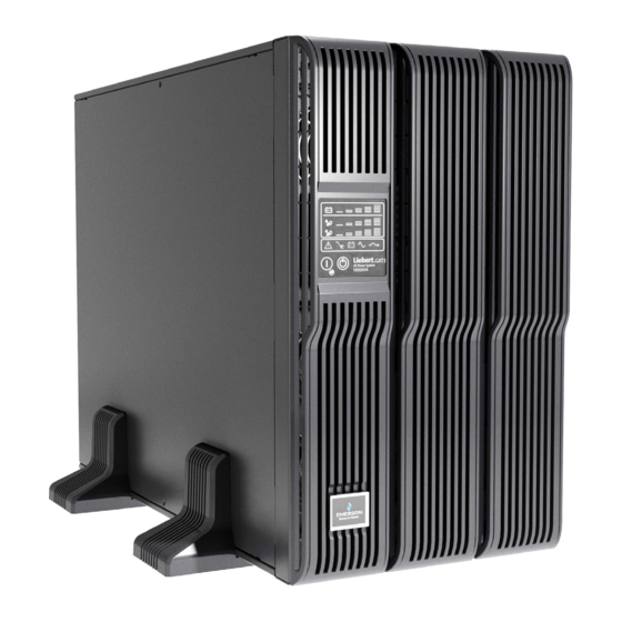
- Page 1 AC Power For Business-Critical Continuity™ Liebert GXT3 208V, 5000-10,000VA, 6000RTL630 ® ™ User Manual...
-
Page 3: Table Of Contents
TABLE OF CONTENTS ............4 NTRODUCTION . - Page 4 Put the Liebert GXT3 in Manual Bypass ........27 Shut Down the Liebert GXT3 .
- Page 5 FIGURES Figure 1 Liebert GXT3 front view—rack-mount and tower configurations ......7 Figure 2 Liebert GXT3 5000VA and 6000VA rear view ......... 7 Figure 3 Input power hardwire boxes—5000 and 6000VA models .
-
Page 7: Save These Instructions
“critical” devices. Maximum load must not exceed that shown on the UPS rating label. The UPS is designed for data processing equipment. If uncertain, consult your dealer or local Emerson Network Power representative. This UPS is designed for use on a properly grounded (earthed), 100/200, 110/220, 115/230, 120/208,120/240 or 127/220VAC, 50 or 60Hz supply. - Page 8 The Liebert GXT3 series complies with the requirements of EMC Directive 2004/108/EC and the pub- lished technical standards. Continued compliance requires installation in accordance with these instructions and use of accessories approved by Emerson. NOTICE This is a product for restricted sales distribution to informed partners. Installation restrictions or additional measures may be needed to prevent radio interference.
- Page 9 LOSSARY YMBOLS Risk of electrical shock Indicates caution followed by important instructions AC input AC output Requests the user to consult the manual Indicates the unit contains a valve-regulated lead acid battery PbH2SO4 Recycle DC voltage Equipment grounding conductor Bonded to ground AC voltage ON/Alarm Silence/Manual Battery Test OFF/Bypass...
-
Page 10: Introduction
Introduction NTRODUCTION Congratulations on your choice of the Liebert GXT3 uninterruptible power system (UPS). The Liebert GXT3 comes in nominal power ratings of 5000VA, 6000VA, 8000VA and 10,000VA. It is designed to provide conditioned power to microcomputers and other sensitive electronic equipment. When it is generated, alternating current is clean and stable. -
Page 11: System Description
System Description YSTEM ESCRIPTION Output Input Static Bypass TVSS & Rectifier/PFC EMI/RFI DC-to-DC Filters Converter Inverter Battery Battery Charger Transient Voltage Surge Suppression (TVSS) and EMI/RFI Filters These UPS components provide surge protection and filter both electromagnetic interference (EMI) and radio frequency interference (RFI). They minimize any surges or interference present in the util- ity line and keep the sensitive equipment protected. -
Page 12: Battery
System Description Battery The Liebert GXT3 utilizes valve-regulated, nonspillable, lead acid batteries. To maintain battery design life, operate the UPS in an ambient temperature of 15°C to 25°C (59°F to 77°F). Optional external battery cabinets are available to extend battery run times. For run times, see Table 14. Dynamic Bypass The Liebert GXT3 provides an alternate path for utility power to the connected load in the unlikely event of a UPS malfunction. -
Page 13: Major Components
Major Components AJOR OMPONENTS The Liebert GXT3 is composed of three major assemblies to provide easier handling, installation and versatility. Main Frame and Electronics All models of the Liebert GXT3 are shipped without the internal batteries installed. Power distribu- tion varies by model and rating. •... -
Page 14: Figure 4 Liebert Gxt3-6000Rtl630, Rear View
Major Components Figure 4 Liebert GXT3-6000RTL630, rear view Output Breaker for Output Breaker REPO Connection Terminal Block for L6-30R #4 L6-20R #2 and #3 Block Communication USB Port External Battery Liebert Connector IntelliSlot Port IT Power Input Breaker System for L6-30P #1 Access Cover Output Breaker... -
Page 15: Removable Power Distribution Box
Major Components Removable Power Distribution Box The UPS is shipped with a power distribution pack installed. This box contains the UPS input circuit breaker. Figure 6 Power distribution models for 5000VA and 6000VA models of Liebert GXT3 Output Power Breakers Push Button Output Maintenance for Pigtails... -
Page 16: Internal Battery Packs
Major Components Figure 7 Power distribution models for 8000VA and 10,000VA models of Liebert GXT3 similar features on other distribution boxes arranged differently 5-20R Output Output Circuit Breaker Receptacles Switch for L6-30R Pigtail #1 L6-30ROutput Push Button Receptacles Circuit Breakers for 5-20R Receptacles 5-20R Output... -
Page 17: What S Included
What’s Included ’ NCLUDED The Liebert GXT3 is shipped with the following items: • Terminal Block Communication terminals • Compact disc with: • Liebert MultiLink • Configuration program • User manual (electronic version) • USB cable, one; 2m (6-1/2 ft.) long •... -
Page 18: Installation And Configuration
8.2 - Initial Startup and Electrical Checks. Visually inspect the UPS for shipping damage. Report any damage to the carrier and your local dealer or Emerson representative. CAUTION The UPS is heavy (see 12.0 - Specifications). Take proper precautions when lifting or moving it. -
Page 19: Rack-Mount Ups Installation
5.1.3 - Installing the Adjustable Rack-Mount Kit—Sold Separately shows the positioning of the rack-mounting brackets. Emerson recommends taking the internal batteries out of the UPS during rack installation. This will make the UPS cabinet lighter and easier to handle. - Page 20 Installation and Configuration The adjustable rack-mounting brackets (Part#: RMKIT18-32) feature retaining latches to prevent users from inadvertently sliding the UPS or battery cabinet out of the rack. To install the rack mount brackets: Return flanges 1. Unpack two rack-mounting bracket assemblies and mounting hardware from this kit.
- Page 21 Installation and Configuration 6. If available, apply a bead of grease 1" (25mm) long at four Apply places inside the bottom, curved tracks of the front members grease as shown below right. The grease will allow the equipment to UPS or slide into the bracket assemblies more easily..
-
Page 22: External Battery Cabinet Installation
3. Securing hardware and slide rails are sold separately. Please contact your local dealer or Emerson representative for these additional options and any assistance needed. Fasten the slides into position with the screws per the instructions included with the slide rails. -
Page 23: Connect Input/Output Power
Installation and Configuration NOTE If the UPS is to be shipped or stored for an extended time, the connector should be disconnected. This will minimize any standby current drain on the batteries and help attain their design life. Connect Input/Output Power WARNING Risk of electric shock. -
Page 24: Remove The Power Distribution Cover From 8000 And 10,000Va Models
Installation and Configuration 5.3.2 Remove the Power Distribution Cover from 8000 and 10,000VA Models 1. Shut down the Liebert GXT3 by pressing the Standby/Manual Bypass button twice while the UPS is in Bypass Mode, each time holding the button down for about 2 seconds. (For help, refer to 8.5 - Shut Down the Liebert GXT3.) 2. -
Page 25: Install The Power Distribution Box On 8000 And 10,000Va Models
Installation and Configuration 5.3.4 Install the Power Distribution Box on 8000 and 10,000VA Models 1. With the cover or distribution box removed, press the UPS and distribution box connectors together. Ensure that the connectors are fully seated. 2. Align the screw holes and press the power distribution box onto the UPS, making sure that the tabs at the bottom of the box fit into the slots on the UPS. -
Page 26: Figure 16 Terminal Block Connections
Installation and Configuration Terminal Block Connections Conduit entry holes are provided on the rear and side of the box. Input and output wiring should not share the same conduit. Emerson recommends using strain relief when installing the wire. Table 2 Electrical specifications... -
Page 27: It Power System Configuration-Liebert Gxt3-6000Rtl630 Only
Installation and Configuration IT Power System Configuration—Liebert GXT3-6000RTL630 Only WARNING Risk of electric shock. Can cause injury or death. Disconnect all local and remote electric power supplies before working within. Ensure that the Liebert GXT3 is shut down and power has been disconnected before beginning any work on or in the unit. -
Page 28: Configuration Program
Configuration Program ONFIGURATION ROGRAM The final step of installation may require custom configuration of your UPS using the enclosed config- uration program. Some configuration settings may be changed only while the UPS is off. These should be set before the UPS is put into full-time service powering the critical load. For most users operating with 230VAC and with no external batteries, the factory default settings will be adequate. -
Page 29: Controls And Indicators
• After 24 hours, retest the batteries. • After the batteries have been retested, if only three of the five Battery LEDs illuminate, contact your local dealer, Emerson representative or Emerson Channel Support. Standby/Manual Bypass Button This button controls output power to connected load(s) and has dual functions: Standby and Manual Bypass. -
Page 30: Load Level Indicators (4 Green, 1 Amber)
Controls and Indicators Load Level Indicators (4 Green, 1 Amber) The load level indicator is composed of five sets of LED bars that illuminate to indicate the relative load on the UPS output in 25% increments (±5%). The load level indicator will illuminate as shown in Figure 19. -
Page 31: Ups Status Indicators
Controls and Indicators UPS Status Indicators UPS status is indicated by five symbols: fault indicator, AC input indicator, battery indicator, inverter indicator and bypass indicator. Table 3 shows the symbols and their meanings. Table 3 UPS status indicators UPS Status Indicator Icon Color... -
Page 32: Operation
Operation PERATION This section describes checks to be made before starting the UPS, how to start the UPS, manual bat- tery test, manual bypass, shutting down the UPS and disconnecting the utility power from the UPS. NOTE The Liebert GXT3’s battery has been fully charged before delivery, but some charge will be lost during storage and shipping. -
Page 33: Manual Battery Test
• If none of the five Battery LEDs illuminate during the second manual battery test, replace batter- ies and contact your local Emerson representative or Emerson Channel Support. Put the Liebert GXT3 in Manual Bypass Press the Standby/Manual Bypass button and hold it for about 2 seconds while the UPS is in Utility (AC) Mode. -
Page 34: Communication
Communication OMMUNICATION Communication Interface Port The Liebert GXT3 UPS has a terminal block on the rear of the UPS unit. Several signals are provided on this port and are assigned as follows. Terminal Block The terminal block includes eight pins, as shown in Figure 21. Figure 21 Terminal block communication pin layout Low Battery On-Battery... -
Page 35: On Battery
Communication Activation of the Battery Mode Shutdown will be logged as an event in the event history log. NOTE Remote Power Off will be performed by NO contact. The current limited source for the optocoupler (+12VDC, 50mA) will be available from UPS. The connection to the Liebert GXT3 for remote connection will be via terminal block connector. -
Page 36: Liebert Multilink
Liebert MultiLink License Kit. For more information about the Liebert IntelliSlot SNMP/Web Card and Liebert MultiLink License Kits, visit our Web site (www.liebert.com) or contact your local dealer or Emerson representative. Several option cards are available for use in the Liebert IntelliSlot port of the Liebert GXT3. The Lie- bert IntelliSlot SNMP/Web Card provides SNMP and Web-based monitoring and control of the UPS across the network. -
Page 37: Maintenance
The Liebert GXT3 is designed to allow the user to replace the internal battery pack safely. Read the safety cautions before proceeding. Contact your local dealer or Emerson representative to obtain the part number and pricing of the appropriate replacement battery pack. -
Page 38: Battery Charging
The Liebert GXT3 charges the batteries continuously when it is connected to the utility input power. If the Liebert GXT3 will be stored for a long time, Emerson recommends connecting the UPS to input power for at least 24 hours every four to six months to ensure full recharge of the batteries. -
Page 39: Checking Ups Status
Emerson Channel Support. • Check whether the battery is discharging. When the utility input is normal, the battery should not discharge. If the UPS is operating in Battery Mode, stop and contact your local Emerson rep- resentative or Emerson Channel Support. -
Page 40: Figure 25 Removing Power Module From Liebert Gxt3 8000 And 10,000Va Models
Maintenance Figure 25 Removing power module from Liebert GXT3 8000 and 10,000VA models Power module pulled part of the way out of an 8000 or 10,000VA unit 11. Insert the replacement UPS power module. 12. Slide the power module restraint lever back into the locked position. 13. -
Page 41: Troubleshooting
Troubleshooting 11.0 T ROUBLESHOOTING This section indicates various UPS symptoms a user may encounter and provides a troubleshooting guide in the event the UPS develops a problem. Use the following information to determine whether external factors caused the problem and how to remedy the situation. 11.1 UPS Symptoms The following symptoms indicate the Liebert GXT3 is malfunctioning:... -
Page 42: 11.1.2 Audible Alarm
Check load level indicator and reduce the load on the UPS has reduced battery UPS is overloaded UPS. backup time Replace batteries. Contact your local dealer, Emerson Batteries may not be able to representative or Emerson Channel Support for hold a full charge due to age replacement battery kit. - Page 43 When reporting a UPS issue to Emerson, include the UPS model and serial number. These are on the top panel of the Liebert GXT3.
-
Page 44: Specifications
Specifications 12.0 S PECIFICATIONS Table 7 UPS specifications—5000, 6000, 8000 and 10,000 models Model Number GXT3-5000RT208 GXT3-6000RT208 GXT3-8000RT208 GXT3-10000RT208 Model Rating 4000W/5000VA 4800W/6000VA 7200W/8000VA 9000W/10000VA Dimensions, Rack Mount, W x D x H Unit, in. (mm) 16.9 x 26.1 x 6.8 (430 x 662 x 173) 16.9 x 26.5 x 10.3 (430 x 672 x 261) Shipping, in. -
Page 45: Table 8 Ups Specifications-Liebert Gxt3-6000Rtl630
Specifications Table 8 UPS specifications—Liebert GXT3-6000RTL630 Model Number GXT3-6000RTL630 Model Rating 4200W/6000VA Dimensions, Rack Mount, W X D X H, in. (mm) Unit 16.9 x 22.6 x 8.5 (430 x 574 x 217) Shipping 20.9 x 29.3 x 14.8 (530 x 745 x 377) Weight, lb (kg) Unit 51.8 (23.5) -
Page 46: Table 9 Operating Temperature Parameters
Specifications Table 9 Operating temperature parameters pf @30°C ±3°C pf @40°C ±3°C Ambient Temperature, °C (°F) (pf @ 86°F ±5.4°F) (pf @ 104°F ±5.4°F) GXT3-5000/6000RT208 0.8pf 0.8pf GXT3-6000RTL630 0.7pf 0.7pf GXT3-8000/10000RT208 0.9pf 0.8pf Table 10 Internal battery cabinet specifications GXT3-144BATKIT GXT3-240BATKIT GXT3-288RTBKIT Model Number... -
Page 47: Table 11 External Battery Cabinet Specifications
Specifications Table 11 External battery cabinet specifications Model Number GXT3-144VBATT GXT3-240VBATTUL GXT3-288RTVBATT GXT3-5000 & GXT3-8000 & Used w/UPS Model GXT3-6000RT208 GXT3-6000RTL630 GXT3-10000RT208 Dimensions, W x D x H, in. (mm) 16.9 x 26.1 x 3.3 16.9 x 22.6 x 5.1 16.9 x 26.5 x 6.8 Unit (with bezel) (430 x 662 x 85) -
Page 48: Table 13 Power Distribution Box Specifications For Gxt3-8000Rt208 And Gxt3-10000Rt208
Specifications Table 13 Power distribution box specifications for GXT3-8000RT208 and GXT3-10000RT208 Power Distribution Box Model # PD Model Number PD2-101 PD2-102 PD2-103 PD2-104 PD2-105 PD2-106 Dimensions, W x D x H, in. (mm) 7.4 x 5.7 7.4 x 5.7 7.4 x 5.7 7.4 x 5.7 7.4 x 5.7 7.4 x 5.7... -
Page 49: Table 14 Battery Run Time, Minutes
Specifications Table 14 Battery run time, minutes Run Time, Minutes Number of Batteries Load GXT3-6000RTL630 GXT3-5000RT208 GXT3-6000RT208 GXT3-8000RT208 GXT3-10000RT208 13.5 Internal Battery 100% Internal Battery + 1 External Battery Cabinet 100% Internal Battery + 2 External Battery Cabinet 100% Internal Battery + 3 External Battery... -
Page 50: Auto-Learning Battery Run Times
Specifications 12.1 Auto-Learning Battery Run Times As batteries age, the estimated runtimes may become less accurate. The Liebert GXT3 is pro- grammed to “learn” from a full battery discharge and modify the estimated run time for the measured battery capacity. This can improve accuracy and compensate for aging batteries or batteries that operate at different ambient temperatures. - Page 52 Power Switching & Controls Services DC Power Infrastructure Management & Monitoring Precision Cooling Surge Protection Emerson, Business-Critical Continuity, Emerson Network Power and the Emerson Network Power logo are trademarks of Emerson Electric Co. or one of its affiliated companies. ©2010 Emerson Electric Co.