Table of Contents
Quick Links
Table of Contents
Troubleshooting

Related Manuals for Motorola 7545MBW


Summary of Contents for Motorola 7545MBW
- Page 1 OMNII HAND-HELD COMPUTER (WINDOWS CE 6.0) USER GUIDE...
- Page 3 OMNII HAND-HELD COMPUTER USER GUIDE (Windows Hand-Held CE 6.0) 8000211.G March 10, 2014...
- Page 4 Windows® and the Windows Logo are trademarks or registered trademarks of Microsoft Corporation in the United States and/or other countries. The Bluetooth® word mark and logos are owned by Bluetooth SIG, Inc. and any use of such marks by Motorola is under license.
-
Page 5: Revision History
Revision History Changes to the original guide are listed below: Change Date Description -01 Rev G 03/2014 Motorola rebrand. -
Page 7: Table Of Contents
Table of Contents TABLE OF CONTENTS About This Manual .......................... xiii Text Conventions ..........................xiv Overview of the Omnii Hand-Held Computer.................. xiv Regulatory Labels ........................... xviii Chapter 1: Basic Operation Omnii Features ..........................1-3 Omnii Modules Available ........................ 1-5 Documents Available ........................1-6 Preparing the Omnii for Operation .................... - Page 8 The Taskbar ........................2-21 The Start Menu ........................2-22 The Kiosk Desktop Shell......................... 2-27 Restoring the Windows Classic Shell.....................2-29 General Maintenance ........................2-29 Caring for the Touchscreen ......................2-29 Cleaning the Omnii .........................2-30 Chapter 3: Configuration Overview of Software........................3-5 Motorola Software Advantage ......................3-5...
- Page 9 Table of Contents iii Microsoft Software..........................3-5 The Control Panel ........................... 3-6 Control Panel Applications ......................3-6 App Launch Keys..........................3-10 ® Bluetooth Setup .......................... 3-11 Paired ............................3-12 Device ............................3-13 Discovering and Removing Devices ................... 3-13 Filtering By Class of Device (COD)..................3-14 Device Pop-up Menu......................
- Page 10 Omnii Hand-Held Computer with Windows CE 6.0 User Manual Lock Sequence..........................3-39 Manage Triggers..........................3-40 Trigger Mappings..........................3-41 Add and Edit Trigger Mapping......................3-42 Microphone ............................ 3-43 Open TekTerm ..........................3-43 PartnerUp ............................3-43 Pocket PC Compatibility ......................... 3-44 Power Properties ..........................3-44 Battery Capacity ..........................3-44 Power Saving Suspend ........................3-45 Suspend Threshold and Estimated Battery Backup ..............3-45...
- Page 11 Table of Contents v Managing Profiles...........................3-70 Viewing a Profile ......................... 3-70 Profile Options........................3-70 Deleting a Profile ..........................3-72 TweakIt............................3-72 Advanced............................3-73 Advanced CE Services Settings ..................3-73 Advanced Interface and Network Settings ................3-73 Advanced Services Settings ....................3-74 Registry Editor ..........................3-74 Voice –...
- Page 12 Omnii Hand-Held Computer with Windows CE 6.0 User Manual Snap Modules..........................4-7 AC Wall Adaptor - Models ST1050 and ST1050-AR ..............4-9 Vehicle Power Outlet Adaptor - Model ST3113................4-9 Chargers and Docking Stations: General Information ..............4-10 Important Charger Safety Instructions....................4-10 Charging the Battery........................4-10 Installation —...
- Page 13 Table of Contents vii Charge Indicators ...........................4-27 Charging Batteries..........................4-27 Troubleshooting..........................4-27 Improper Battery Storage ....................4-27 Power Self-test LEDs Don’t Light Up .................. 4-27 Indicator Does Not Light When Battery Installed ..............4-28 Appendices Appendix A: Port Pinouts Omnii Docking Connector ....................... A-3 Snap Modules Connectors......................
- Page 14 viii Omnii Hand-Held Computer with Windows CE 6.0 User Manual Modifying a Barcode Setting ....................B-15 Translation Menu – Configuring Rules..................B-16 Advanced Menu ........................B-16 File Locations for Captured Images ..................B-16 Configuring Triggers......................B-17 Barcode Symbologies........................B-18 Imager Barcode Symbologies....................B-19 Color Camera Barcode Symbologies..................
- Page 15 Table of Contents ix Appendix E: Omnii Specifications The Omnii Hand-Held Computer (Model 7545) ................E-3 Hardware ..........................E-3 Regulatory Approvals........................ E-5 Lithium-ion Smart Battery 5000 mAh (ST3001) ................E-5 Wireless Radios ..........................E-6 Cinterion MC75i GSM/GPRS/EDGE Radio ................E-6 Cinterion PH8-P GSM/GPRS/EDGE/UMTS/HSPA+ Radio ............
- Page 16 Table of Contents x Appendix H: Wireless Zero Config Settings Wireless Information ........................H-3 Wireless Statistics ........................H-3 Wireless Information ........................ H-4 Assigning An IP Address ........................ H-6 Name Server..........................H-6 Advanced Features......................... H-7 Rearranging Preferred Networks ....................H-7 Deleting A Preferred Network ....................H-7 Changing Network Properties ....................
-
Page 17: About This Guide
ABOUT THIS GUIDE ABOUT THIS GUIDE About This Manual ..........xiii Text Conventions . -
Page 19: About This Manual
Desktop Start Menu: Programs and Settings>Control Panel. The software includes both Motorola Software Advantage and Microsoft programs, and details how to use them to configure the Omnii, along with scanners/imagers, Bluetooth, etc. -
Page 20: Text Conventions
XT15f Freezer Variants”. NOTE The Omnii Hand-Held Computer is a body worn device, and to maintain compli- ance with the FCC RF exposure guidelines, use a Motorola approved carrying case. Use of non-approved accessories may violate FCC RF exposure guidelines. NOTE For product specifications, refer to Appendix E: “Omnii... - Page 21 - Signature capture • Keyboards - Large selection of backlit keypads in both alpha and numeric formats. For a list of currently available keyboard configurations, consult your Motorola representative, or go to: http://www.motorolasolutions.com/US-EN/Product+Lines/Psion/?WT.mc_id=psion_us_p_handheld • Voice, Audio & Feedback - High volume beeper: 95 dBA...
- Page 22 xvi Omnii Hand-Held Computer with Windows CE 6.0 User Manual Wireless Connectivity • Integrated Bluetooth® V2.0 + EDR • Integrated 802.11a/b/g/n WiFi • Bluetooth® coexistence • CCX v4 • Optional SIRF III GPS Receiver • Optional GPS/GPRS/EDGE WWAN radio • Optional GPS/GPRS/EDGE with UMTS/HSPA+ WWAN radio NOTE 802.11b/g and Bluetooth are available simultaneously.
- Page 23 About This Guide xvii Omnii XT15f Freezer Variants Figure 2 Numeric Alphanumeric Bottom View (Docking Connector) Figure 3 Top View (Scanner Window) Figure 4 Laser Aperture...
-
Page 24: Regulatory Labels
xviii Omnii Hand-Held Computer with Windows CE 6.0 User Manual Regulatory Labels Laser Warning Label Figure 5 WARNING Using controls or adjustments or performing procedures other than those specified herein may result in hazardous radiation exposure. This label is affixed below the scanner window. SE955 Laser Warning Label Figure 6 SE965 and SE4500 Laser Warning Label... - Page 25 About This Guide SE4600 Laser Warning Label Figure 9 Thi l b l i ffi d b l...
-
Page 27: Chapter 1 Basic Operation
CHAPTER 1 BASIC OPERATION BASIC OPERATION Omnii Features ..........1-3 Omnii Modules Available . -
Page 29: Omnii Features
Basic Operation 1 - 3 Omnii Features Front View of the Omnii XT15 Model with Alphanumeric Keyboard Figure 1-1 Speaker Beeper LEDs Display Scan Key Microphone SYM Key FN Modifier Key Enter/Power Key NOTE The Omnii 55- and 66-key keyboards are equipped with a Power button as shown in Figure 1-1 Front View of the Omnii XT15 Model with Alphanumeric Keyboard on page... - Page 30 1 - 4 Omnii Hand-Held Computer with Windows CE 6.0 User Manual Side Views of the Omnii XT15 Figure 1-2 Left Side Right Side Volume rocker button Vertical scroll button Scan button Enter button Battery release button Side rail Slot for Snap Module arm Bottom View Figure 1-3 1 - Docking Connector...
-
Page 31: Omnii Modules Available
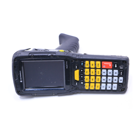
Camera Aperture Rear PTT Speaker (optional) Scanner Window Scanner Pod Expansion Back Pistol Grip Attachment Screws (4) Battery Pack Omnii Modules Available To see a current list of Omnii accessories and modules, please go to the Motorola website at: http://www.motorolasolutions.com/US-EN/Product+Lines/Psion/?WT.mc_id=psion_us_p_handheld... -
Page 32: Documents Available
1 - 6 Omnii Hand-Held Computer with Windows CE 6.0 User Manual Documents Available To see a current list of documents and download what you need, please go to the Knowledge Base on the Motorola IngenuityWorking community website: http://community.psion.com/knowledge/w/knowledgebase/product-manuals.aspx Preparing the Omnii for Operation The Battery The Omnii is powered by a Lithium-ion Smart Battery pack, 5000 mAh —... -
Page 33: Switching The Omnii On And Off
IMPORTANT If your Omnii fails to power up, consider the following troubleshooting options: The battery may be overheated (>60C°), a non-Motorola battery may be installed, or the battery may have fallen below the configured Suspend Thresh- old. See “Suspend Threshold and Estimated Battery Backup”... -
Page 34: Resetting The Omnii
1 - 8 Omnii Hand-Held Computer with Windows CE 6.0 User Manual IMPORTANT If the word ‘FN’ is displayed underlined in the taskbar area at the bottom of the screen, this key is locked “on” and the Omnii will not switch off. -
Page 35: Performing A Clean Start
Replace the battery and power Omnii on. The terminal will boot as if from a cold reset. Attaching Carrying Accessories Motorola recommends that a carrying accessory — a hand strap — be installed on the Omnii before use. For detailed information, please see “Carrying and Protective Accessories”... -
Page 36: Calibrating The Touchscreen
1 - 10 Omnii Hand-Held Computer with Windows CE 6.0 User Manual Calibrating the Touchscreen NOTE The touchscreen function can be turned off (see “Touch” on page 3-67). The Omnii touchscreen feature is factory-calibrated and ready-to-go; however, over time the touchscreen's operating parameters may change, and it may need to be recalibrated for correct operation. -
Page 37: Voice Communication
Basic Operation 1 - 11 Voice Communication If the MC75i EDGE or the Cinterion PH8-P HSPA+ WWAN radio modem is installed and enabled, the Phone icon and the GSM signal strength icon will appear automatically on the taskbar. For details on using your Voice options, please refer to “Voice –... -
Page 39: Chapter 2 Getting To Know Your Omnii
CHAPTER 2 GETTING TO KNOW YOUR OMNII GETTING TO KNOW YOUR OMNII Operating System ..........2-3 Battery Details . - Page 40 2 - 2 Omnii Hand-Held with Windows CE 6.0 User Manual Scanning Techniques ........2-16 Scanner Status LED, Sounds, and Vibrations .
-
Page 41: Operating System
Getting To Know Your Omnii 2 - 3 Operating System ® ® • Microsoft Windows Embedded CE 6.0 Battery Details Omnii Hand-Held Computers are powered by a lithium-ion battery pack, Model ST3001. Please see the following sections for detailed battery information: •... -
Page 42: Charging The Battery
IMPORTANT If your Omnii fails to power up, consider the following troubleshoot- ing options: The battery may be overheated (>60C°), a non-Motorola battery may be installed, or the battery may have fallen below the config- ured Suspend Threshold. See “Suspend Threshold and Estimated Battery Backup”... -
Page 43: Regular Keys
Getting To Know Your Omnii 2 - 5 Keyboard Layouts Figure 2-1 [SCAN] Key [SYM] Key [FN] Modifier Key [Enter/Power] Key [SHIFT] Modifier Key [Windows] Key 36-Key Numeric 123 Keyboard 59-Key Alpha ABC Keyboard The Power Button (55-Key and 66-Key Keyboards only) The [Power] button in the upper right corner of the keyboard switches the unit on and off. -
Page 44: Modifier Keys
2 - 6 Omnii Hand-Held with Windows CE 6.0 User Manual The [SHIFT] Key The [SHIFT] key is used to display uppercase alpha characters and to provide access to other symbols and functions on the numeric keyboards. Press the [SHIFT] key to turn the shift state 'on' (it will be represented by an up arrow in the taskbar), then press another key to access the shifted function of that key. -
Page 45: Activating Modifier Keys
Getting To Know Your Omnii 2 - 7 [SHIFT] and [FN] The [SHIFT] and [FN] modifier keys provide access to additional keys and system functions. The functions related to these modifier keys are colour-coded in white and blue print respectively above the keyboard keys, dependant on your keyboard format. -
Page 46: Function Keys And Macro Keys
2 - 8 Omnii Hand-Held with Windows CE 6.0 User Manual NOTE The locking function of the modifier keys can be changed so that pressing a key once will lock the key on. If you disable the One Shot function of the key, pressing it once will lock the key on. -
Page 47: Numeric Keyboards - Accessing Alpha Keys
Getting To Know Your Omnii 2 - 9 To access a macro key, press the [FN] key followed by the macro key. 36-Key Numeric Keyboard Macro Keys These keyboards are equipped with five macro keys: [M1] to [M5]. These keys are colour coded in blue print above function keys [F1] to [F5]. -
Page 48: The Keypad Backlight
2 - 10 Omnii Hand-Held with Windows CE 6.0 User Manual To access CAPS LOCK mode, press [FN] + [SHIFT]. In this state, if you press a numeric key, the number is displayed rather than the normal shifted function of that key. Press [FN] + [SHIFT] again to turn the CAPS LOCK mode off. -
Page 49: Indicators
Getting To Know Your Omnii 2 - 11 Indicators The Omnii uses LEDs (Light Emitting Diodes), onscreen messages, vibrations, and audio tones as indicators. LEDs The Omnii is equipped with four coloured LEDs. This section outlines what these LEDs indicate. IMPORTANT If an LED is illuminated in red, the operator should be cautious as this generally indicates an abnormal operating condition or active... -
Page 50: Radio Status Led
2 - 12 Omnii Hand-Held with Windows CE 6.0 User Manual Operating LED Behaviour Function OFF when unit is in Suspend or Normal operating status. Shutdown. Solid Yellow The unit is powering on. Fast Flashing Yellow The unit is entering Suspend mode. Flashing Yellow This LED is controlled by the Microsoft NLED api. - Page 51 Getting To Know Your Omnii 2 - 13 Taskbar Figure 2-4 The taskbar changes dynamically, and only those icons that are applicable are displayed. For example, if a radio is not installed in your Omnii, the radio signal icon is not displayed in the taskbar. ®...
-
Page 52: Audio Indicators
2 - 14 Omnii Hand-Held with Windows CE 6.0 User Manual Docking Device When a hand-held is inserted in a docking station, charger or cradle, an associated icon appears in the taskbar. Combo Charger & Quad Docking Station Powered Vehicle Cradle, Desktop Dock Combo Docking Station &... -
Page 53: Scanners And Imagers
Getting To Know Your Omnii 2 - 15 • Use a Phillips screwdriver to remove the SD cover screw. Flip the cover open or remove it. For a microSD card: • Slide the microSD card door to the left to unlock it. Flip it open. •... -
Page 54: Basic Scanner Operations
2 - 16 Omnii Hand-Held with Windows CE 6.0 User Manual • “Scanner Status LED, Sounds, and Vibrations” on page 2-17 details how to interpret whether or not a barcode has been successfully scanned. • Barcode Parameters: Appendix C: “Scanner Settings”. -
Page 55: Scanner Status Led, Sounds, And Vibrations
Getting To Know Your Omnii 2 - 17 Scanner Status LED, Sounds, and Vibrations The scanner LED (the far right LED) indicates whether or not your scan is successful. The LED behaves as follows: • Scan In Progress: scan LED displays solid red colour. •... -
Page 56: Operating Internal Two Dimensional (2D) Imagers
2 - 18 Omnii Hand-Held with Windows CE 6.0 User Manual Operating Internal Two Dimensional (2D) Imagers An imager scanner takes a snap shot of a single barcode or multiple barcodes (at one time). It can find a barcode regardless of its orientation — that is, even a barcode printed at a 45 degree angle to the hand-held will be decoded successfully. -
Page 57: Windows Embedded Ce 6.0
Getting To Know Your Omnii 2 - 19 Windows Embedded CE 6.0 Navigating in Windows Embedded CE and Applications Graphic user interfaces such as Windows Embedded CE for portable devices and desktop Windows (Windows Vista™, Windows 7, Windows 8, etc.) utilize point and click navigation. An equivalent keyboard shortcut is also available for every point and click action. -
Page 58: The Windows Classic Shell Startup Desktop
2 - 20 Omnii Hand-Held with Windows CE 6.0 User Manual Operation Key or Key Combination Select Radio Button/Press Button [SPACE] Go to Start Menu [Windows] Keep in mind that unlike a desktop computer, the Omnii does not support key chording (pressing two keys at the same time). -
Page 59: The Taskbar
Getting To Know Your Omnii 2 - 21 The Taskbar The Omnii is equipped with a taskbar at the bottom of the screen. It displays icons through which you can view the battery capacity and radio signal quality of your unit. If the hand-held is attached to a charger, cradle, docking station, or Snap Module, an associated icon is displayed. -
Page 60: The Start Menu
2 - 22 Omnii Hand-Held with Windows CE 6.0 User Manual • Highlight the Settings option, highlight Taskbar in the sub-menu, and press [Enter]. The Taskbar and Start Menu dialog box is displayed. • Tap on the items you want to activate or deactivate. The check mark indicates active items. If you’re using the keyboard: •... - Page 61 Getting To Know Your Omnii 2 - 23 Programs • Choose Programs to display a sub-menu of options. The programs displayed will be those resident in the Windows\Programs folder of the computer. Program Sub-Menu Figure 2-6 This sub-menu allows you to choose Command Prompt, Internet Explorer, installed applications (e.g., Micro- soft WordPad), Kiosk Access, Remote Desktop Connection, Wi-Fi Config, or Windows Explorer.
- Page 62 2 - 24 Omnii Hand-Held with Windows CE 6.0 User Manual Remote Desktop Connection Remote Desktop Connection is an Omnii application used to connect to a Windows Terminal Server so that you can run a “session” on the Server machine using the hand-held (Windows Embedded CE device). “Remote Desktop Connection”...
- Page 63 Control Panel The Control Panel contains applets used to configure hardware, the operating system and the shell. If your Omnii is running with the Motorola TekTerm application or another application, additional configuration applets may appear in the Control Panel. Network and Dial-Up Connections The Network and Dial-up Connections window allows you to configure the Omnii network interfaces or execute an existing configuration.
- Page 64 2 - 26 Omnii Hand-Held with Windows CE 6.0 User Manual Choosing the Run option from the Start Menu displays a dialog box in which you can enter the name of the program, folder or document you want to open or launch. Shutdown The Shutdown menu includes these options: Suspend, Warm Reset and Cold Reset.
-
Page 65: The Kiosk Desktop Shell
Getting To Know Your Omnii 2 - 27 The Kiosk Desktop Shell The appearance and actions of the desktop can be changed by tapping on the Kiosk Shell icon on your desktop, which activates the Kiosk shell. NOTE The Omnii will be reset if you choose to switch shells. Switch to Kiosk Shell Figure 2-9 After resetting the Omnii, the desktop appearance will be very different. - Page 66 2 - 28 Omnii Hand-Held with Windows CE 6.0 User Manual A different program, Kiosk Access, enables you to customize your computer settings, remove or add shortcuts to the Favourites Bar and Control Panel, and limit access to various different components on the computer and the system tray icons for security.
-
Page 67: Restoring The Windows Classic Shell
Getting To Know Your Omnii 2 - 29 Restoring the Windows Classic Shell The default Desktop appearance and actions can be restored by tapping on the Kiosk Shell icon in the Favourites Bar. Shell Switch to Windows Classic Shell Desktop Figure 2-10 NOTE The Omnii will be reset if you choose to switch shells. -
Page 68: Cleaning The Omnii
2 - 30 Omnii Hand-Held with Windows CE 6.0 User Manual Cleaning the Omnii IMPORTANT Do not immerse the unit in water. Dampen a soft cloth with mild detergent to wipe the unit clean. To prevent damage to the touchscreen, use only your finger or the stylus (pen) supplied with your Omnii. -
Page 69: Chapter 3 Configuration
Overview of Software ......... . .3-5 Motorola Software Advantage ....... . .3-5 Microsoft Software . - Page 70 3 - 2 Omnii Hand-Held with Windows CE 6.0 User Manual Motion Meter ......... .3-26 Settings .
- Page 71 Configuration 3 - 3 Options ..........3-57 Double Click Parameters .
- Page 72 3 - 4 Omnii Hand-Held with Windows CE 6.0 User Manual Encryption ........3-83 EAP .
-
Page 73: Overview Of Software
Motorola Software Advantage Motorola Software Advantage is a collection of applications and features designed to support system adminis- trators and end users. These tools enable enterprises to customize the product to meet their needs and to maximize productivity. -
Page 74: The Control Panel
3 - 6 Omnii Hand-Held with Windows CE 6.0 User Manual The Control Panel The Windows Embedded CE Control Panel provides a group of applications through which you can set a variety of system-wide properties, such as power, keyboard sensitivity, network configuration, system backup, desktop appearance, and so on. - Page 75 Configuration 3 - 7 Bluetooth Opens the Bluetooth Manager which provides options for configuring various Bluetooth peripherals. It also provides the capability to use a Bluetooth-enabled cellular phone as a data modem to exchange information with other Bluetooth devices and provide network access. Certificates This program provides access to the Certificates Manager and Stores.
- Page 76 3 - 8 Omnii Hand-Held with Windows CE 6.0 User Manual Keyboard Toggles character repeat on and off and specifies delay and rate for repeated characters. It also allows you to adjust the keyboard backlight threshold and intensity, and many other functions. Manage Triggers This utility allows you to define buttons as triggers for different devices.
- Page 77 Configuration 3 - 9 Region and Language Allows you to specify the local language that is to be displayed on the hand-held screen along with the format of numbers, currency, time and date for your region. Remove Programs Lists the programs that can be removed from your unit. To remove a program, select it and then click on the Remove button.
-
Page 78: App Launch Keys
3 - 10 Omnii Hand-Held with Windows CE 6.0 User Manual App Launch Keys The App Launch Keys icon allows you to map a key to an application so that you can then launch the applica- tion from a single key-press. •... -
Page 79: Bluetooth ® Setup
Typically, when both radios operate in the hand-held at the same time, they cannot transmit simultaneously — this has a negative impact on overall system throughput. To minimize the impact on the backbone 802.11 network, Motorola recommends using Bluetooth peripherals that have low transaction rates (such as printers and scanners). -
Page 80: Paired
3 - 12 Omnii Hand-Held with Windows CE 6.0 User Manual The Bluetooth Manager allows users to search, pair and connect to other Bluetooth devices within their personal area network. The Bluetooth radio is disabled by default. Before you begin the setup process: •... -
Page 81: Device
Configuration 3 - 13 OBEX OPP (Object Exchange-Object Push Profile) Commands The OPP defines two roles — a Push Server and a Push Client. Push Server is the device that provides an object exchange server. Push Client is the device that pushes and pulls objects to and from the Push Server. OBEX OPP contains the following unique menu option: •... -
Page 82: Filtering By Class Of Device (Cod)
3 - 14 Omnii Hand-Held with Windows CE 6.0 User Manual Filtering By Class of Device (COD) This menu allows you to filter the displayed devices by their COD. If, for example, you choose Computer from this menu, only the devices that have the matching Computer COD value will be displayed. Choosing All lists all detected devices. - Page 83 Configuration 3 - 15 • If the remote device has authentication enabled, type the PIN in this dialog box. • To proceed without authentication, tap on Next. After entering the device PIN, the Services dialog appears with a list of services available for that device. •...
-
Page 84: Servers
3 - 16 Omnii Hand-Held with Windows CE 6.0 User Manual Scanner is used to create a connection to a barcode scanner. A serial connection is created, then the Scanner Services is notified of the connection so that the incoming barcode scan will be forwarded directly to Scanner Services. -
Page 85: Mode
Configuration 3 - 17 Mode Turn on Bluetooth activates the Bluetooth radio. Discoverable determines whether the Omnii is visible or invisible to other devices. Printer Port allows you to assign and enable a virtual outgoing COM port selected from the drop-down menu to communicate with a paired Bluetooth printer. -
Page 86: The Bluetooth Gprs Wan Connection
Local Address displays the MAC address (BD_Addr) of the Bluetooth chip. HCI Version & LMP Version display the version of the chip firmware. Component indicates the version of the Motorola Bluetooth Subsystem (the manager, drivers, etc). Profiles lists the supported profiles on this specific Omnii. - Page 87 Configuration 3 - 19 7. Choose the Next button to display the Modem dialog box. 8. In the drop-down menu labelled Select a modem, choose the name of the modem with which you want to connect, and then choose the Configure button to display the Device Properties dialog box. The Omnii communicates via Bluetooth to your Bluetooth equipped cellular telephone and retrieves the parameters for the Device Properties dialog box.
- Page 88 3 - 20 Omnii Hand-Held with Windows CE 6.0 User Manual The phone number you enter is network carrier dependent. Once you’ve specified all the necessary infor- mation, choose the Finish button. 11. In the Control Panel, choose the Dialing icon. 12.
-
Page 89: Certificates
Configuration 3 - 21 Certificates This program provides access to the Certificate Manager and Stores. The Certificate Manager displays the certificates in the Windows Certificate Store, and allows you to import, delete, and view these certificates. Omnii checks that the certificate has been digitally signed by a certification authority that the Omnii explicitly trusts. -
Page 90: Data Transfer Between Omnii And A Pc
3 - 22 Omnii Hand-Held with Windows CE 6.0 User Manual When the compass recalibration is complete, a message appears on the Omnii screen indicating successful calibration. NOTE The accuracy of the digital compass is affected by the following: a) close proximity to large magnets or metal structures, and b) internal scanner/imager activation. -
Page 91: Using Microsoft Activesync
Configuration 3 - 23 Using Microsoft ActiveSync NOTE If you use a serial port to connect devices like the Omnii to your desktop computer, the connection may not succeed because ActiveSync has trouble connecting at non-default baud rates. To work around this problem, set the ActiveSync baud rate on the desktop to use the same baud rate as the device. -
Page 92: Appearance
3 - 24 Omnii Hand-Held with Windows CE 6.0 User Manual Appearance • In the Display Properties dialog box, open the Appearance tab. This dialog box allows you to customize the display colour scheme. Backlight The backlight is activated for a configurable amount of time. The Display Properties dialog box in the Control Panel allows you to specify the intensity of the backlight along with how long the backlight remains on when the unit is not in use (no key press, scanner trigger, etc.). -
Page 93: Dr. Debug
Tap on Start>Settings>Control Panel. Tap on the Dr. Debug icon. Status This tab indicates the status (on/off) of the debug engines. Tapping on Browse logs displays error logs for your review. The logs should be used as reference when working with Motorola Technical Support personnel. -
Page 94: Utilities
The Utilities tab can be used to log network traffic. When you tap on the Start button, debug data is collected so that, if necessary, it can be forwarded to a Motorola technician for evaluation. The Utilities tab can also be used to log heater control logic board information. -
Page 95: Settings
Configuration 3 - 27 Settings • Choose an Error Level from the drop-down menu. • To change the location where debug information will be stored, tap on the button to the right of the Log Folder option. Error Reporting Error Reporting allows you to enable or disable Microsoft error reporting prompts. •... -
Page 96: Power
3 - 28 Omnii Hand-Held with Windows CE 6.0 User Manual Power This tab allows you to dictate how the GPS module behaves. The GPS Power drop-down menu is used to control when the GPS is powered on and off. •... -
Page 97: Programs
Configuration 3 - 29 Programs Tap on the GPS Program Port drop-down menu to choose the communication (COM) port that the GPS software will use to communicate with the GPS receiver. AGPS To determine your location, a GPS module receives data from three or more GPS satellites in fixed orbit around the Earth. -
Page 98: Info
The Use custom settings option is generally used to configure devices that will have access only to an intranet rather than the Internet and should only be altered with the assistance of qualified Motorola personnel. They will be able to help you configure your Motorola devices and web server to retrieve the ephemeris data. Info This tab provides general information about the GPS module such as the firmware version, the date on which files were last updated, and so on. -
Page 99: Input Panel
Configuration 3 - 31 NOTE This icon is only displayed when the appropriate imager is installed in your Omnii. If there is an imager installed but this icon is not present, additional soft- ware (ICS) may need to be installed. To enable a newly-installed imager, Press and hold down the [FN] key and the [Enter/Power] key simultaneously for a minimum of three seconds. -
Page 100: Keyboard Properties
3 - 32 Omnii Hand-Held with Windows CE 6.0 User Manual IMPORTANT If the Input Panel button icon is not visible in the taskbar, from the Start menu, tap on Settings>Taskbar and Start Menu. Tap the check box next to Show Input Panel Button. To remove this icon from the taskbar, tap in the check box to erase the check mark. -
Page 101: Key Repeat
Configuration 3 - 33 • In the Control Panel, choose the Keyboard icon. Key Repeat NOTE These settings apply when a key is held down continuously. • In the Keyboard Properties dialog box, open the Repeat tab. Repeat Delay The value assigned for this parameter determines the delay in milliseconds between repeat characters. Sliding the Repeat Delay bar to the left increases the delay between key repeats, and sliding the bar to the right shortens the repeat delay time. -
Page 102: Keyboard One Shot Modes
3 - 34 Omnii Hand-Held with Windows CE 6.0 User Manual Intensity This parameter is used to adjust the light intensity of the Omnii keyboard backlight. Sliding the bar to the left darkens the keyboard backlight intensity, and sliding it to the right lightens the intensity. NOTE The keypad backlight maximum brightness will decrease over time as it ages. -
Page 103: Keyboard Macro Keys
Configuration 3 - 35 NOTE Keep in mind that checking the taskbar lets you know whether or not these keys are locked on. For example, if the [FN] key is locked on, the taskbar at the bot- tom of the screen displays it underlined. If this key is displayed without the underline in the taskbar, you’ll know that the key is not locked. -
Page 104: Unicode Mapping
3 - 36 Omnii Hand-Held with Windows CE 6.0 User Manual A message screen is displayed instructing you to Enter Key Strokes to Record. • Type the macro sequence you want to assign to the Macro key. You can type text and numbers, and you can program the function of special keys into a macro. -
Page 105: Scancode Remapping
Configuration 3 - 37 The Unicode Mapping tab is used to map combinations of virtual key values and [CTRL] and [SHIFT] states to Unicode™ values. This tab shows the configured Unicode character along with the Unicode value. For example, the sample screen above shows “a (U+0061)” indicating that the character “a” is represented by the Unicode value “0061”, and so on. - Page 106 3 - 38 Omnii Hand-Held with Windows CE 6.0 User Manual The Normal table defines unmodified key presses; the FN table defines key presses that occur when the [FN] modifier is on; the SYM table defines key presses that occur when the [SYM] modifier is on. The default mappings of these scancodes can be overwritten for each of these three tables using the Scancode Remap- ping tab accessed from the Keyboard Properties dialog box.
-
Page 107: Lock Sequence
Configuration 3 - 39 Virtual Key, Function and Macro The radio buttons at the bottom of the dialog box allow you to define to what the scan code will be remapped: Virtual Key, Function or Macro. When Virtual Key is selected, you can choose to force [SHIFT] to be on or off when the virtual key is sent. If No Force is selected, the shift state is dependent on whether the shift state is on or off at the time the virtual key is sent. -
Page 108: Manage Triggers
3 - 40 Omnii Hand-Held with Windows CE 6.0 User Manual NOTE It is useful to leave the Show popup message enabled (default) so that anyone attempting to use the keyboard will see the key sequence they will need to enter to unlock the keyboard displayed on the screen. -
Page 109: Trigger Mappings
Configuration 3 - 41 Trigger Mappings A trigger mapping is an association between a particular key on the keyboard and a driver or application, the module(s) — sometimes referred to as trigger consumer(s) — of the trigger source. Along with keyboard keys, the external trigger (scan button) is software-based. -
Page 110: Add And Edit Trigger Mapping
3 - 42 Omnii Hand-Held with Windows CE 6.0 User Manual Add and Edit Trigger Mapping These dialogs allow you to add and edit trigger mappings. Trigger Key This drop-down list allows you to specify the source of the trigger events, such as the Soft Scan, Left Scan, etc., for the trigger module selected. -
Page 111: Microphone
The Omnii includes unique features that support Open TekTerm, a Motorola application that has the ability to maintain multiple simultaneous sessions with a variety of host computers. For detailed information, please refer to the Open TekTerm Software User Manual, PN 8000073. -
Page 112: Pocket Pc Compatibility
3 - 44 Omnii Hand-Held with Windows CE 6.0 User Manual Additional pieces of software such as a server must be obtained through Motorola. Tapping on a preloaded client in the PartnerUp screen displays a drop-down menu from which the operator can choose from an array of related options. -
Page 113: Power Saving Suspend
This drop-down menu allows you to specify whether the unit is using AC Power or Battery Power. Suspend Timeout IMPORTANT Motorola recommends setting the Suspend value to 3 minutes. To further reduce power consumption, carefully consider the duration of time that the display backlight is on (see “Backlight”... -
Page 114: Advanced
(such as an SD FLASH card), may need to pay particular attention to this parameter. Motorola does not recommend the storage of any valuable data in system RAM. The Omnii Windows Embedded CE 6.0 environment does not store any critical data in RAM (such as the registry or file system). -
Page 115: Built-In Devices
Configuration 3 - 47 Allow Suspend With This menu allows you to specify whether or not your unit will enter Suspend Mode while it is operating with an active PPP connection, network interface or active TCP/IP connection. Low Power Warnings The sliding scale at the bottom of this menu allows you to specify the remaining battery capacity at which a warning message is displayed on the Omnii screen, from 0% to 20%. - Page 116 3 - 48 Omnii Hand-Held with Windows CE 6.0 User Manual Current Battery Health Meter The Current Battery Health Meter default values are shown here as ***** (Excellent), *** (Used), and * (Battery should be replaced). If you tap on the battery icon in the taskbar, a pop-up screen will show the state of the battery.
-
Page 117: Kiosk Access
Configuration 3 - 49 Kiosk Access Kiosk Access enables you to customize your computer settings, remove or add shortcuts to the desktop and Control Panel, and limit access to various different components on the computer and the system tray icons for security. -
Page 118: Administrator Password
3 - 50 Omnii Hand-Held with Windows CE 6.0 User Manual Administrator Password By setting an Administrator Password, you can limit access to various different components on the computer and the system tray icons for security. The default security setting allows User access to all options, therefore restrictions and settings can be configured without setting a password. -
Page 119: Shell Settings
Configuration 3 - 51 Shell Settings The Shell Settings application has two menus: Applications and Advanced. Applications The Applications menu lists all the applications installed on the computer, alphabetically. The items checked in this view are shown on the Desktop. The Add and Edit buttons allow you to search for and add an application to the list of items in the selection window. -
Page 120: Restrictions
3 - 52 Omnii Hand-Held with Windows CE 6.0 User Manual The following options can be enabled or disabled in the Windows Classic Shell Desktop theme: • Start Menu Bar: If disabled, access to both Start Menu and Notifications are disabled. The Notification tooltips will still display. -
Page 121: Control Panel Settings
Configuration 3 - 53 Advanced The Advanced menu lists the system features you can restrict or block. Notifications The Notifications menu allows you to block or disable notifications. Control Panel Settings In these menus you can set which applets and tabs you want to Hide in Control Panel, and which applets and tabs will be Accessible as a shortcut icon from the Desktop. -
Page 122: Import/Export To File
IMPORTANT A copy of this file should also be saved in a central repository for all Motorola .xml files with a predefined name so that other Motorola util- ities can locate it. Tapping on the Export button will display a “Save As” Export Settings dialog, with the default name Kiosk_Settings.xml, which the Administrator can change even after it has been saved. -
Page 123: Scanners
Configuration 3 - 55 Go to the following website to find information about setting up this connection: http://www.microsoft.com/en-us/download/default.aspx or contact Motorola support services. Locate the office closest to you at: http://www.motorolasolu- tions.com/US-EN/Support/Psion+Services+and+Support?WT.mc_id=psion__support_ Scanners The Scanners icon in the Control Panel provides dialog boxes in which you can tailor barcode scanner config- uration and choose the barcodes your scanner will recognize. -
Page 124: Restoring Default Settings
3 - 56 Omnii Hand-Held with Windows CE 6.0 User Manual NOTE Your Omnii comes preconfigured from the factory for internal scanner types. The type of scanner installed can be determined from the System icon in the Control Panel, under the System Properties tab. IMPORTANT To improve the decode speed and performance, enable (set to on) only those codes that are required by the application. -
Page 125: Options
Configuration 3 - 57 Options This tab allows you to tailor the double-click parameters, display, and data handling options associated with your scanner. Double Click Parameters Click Time (msec) This parameter controls the maximum gap time (in milliseconds) for a double-click. If the time between the first and second clicks of the scanner trigger is within this time, it is considered a double-click. -
Page 126: Data Handling
3 - 58 Omnii Hand-Held with Windows CE 6.0 User Manual NOTE To remove the scan result from the screen before the “Result Time” has expired, point the scanner away from the barcode and press the trigger. Good Scan Beep and Bad Scan Beep These parameters determine whether or not the Omnii emits an audible scanner beep when a good (successful) scan or a bad (unsuccessful) scan is performed. -
Page 127: Translations
Configuration 3 - 59 Translations The Translations menu allows you to define up to 10 cases, each consisting of up to 10 rules in sequential order. Only one case will be applied to a barcode and a case will only be applied if all rules specified in the case are successful —... -
Page 128: Case Rules
3 - 60 Omnii Hand-Held with Windows CE 6.0 User Manual Case Rules The case rules are defined as follows: • No rule — ignored. • Search and replace — replaces all instances of the match string. (Note that this rule cannot fail.) •... -
Page 129: Port Replicator Port A (Com5) And Port B (Com6)
Configuration 3 - 61 Use these settings to ensure that the communication ports on the Omnii match the settings of the serial devices to which they are connected. If the settings do not match exactly, the devices may not function. Note that some devices can auto-detect serial port settings (such as baud rate), and in this case the Omnii will dictate the settings. -
Page 130: Screen Rotation
3 - 62 Omnii Hand-Held with Windows CE 6.0 User Manual Trigger On Sequence And Trigger Off Sequence If a SICK scanner connected to an Omnii port requires a serial stream of data bytes to trigger the scanner on and another to trigger the scanner off, the Trigger On Sequence and Trigger Off Sequence parameters allow you to define these serial streams. -
Page 131: Storage Manager
Configuration 3 - 63 Storage Manager The Storage Manager allows you to view information about the storage devices that are present in the Omnii, such as SD-MMC flash cards and Compact Flash cards. Formatting a Memory Card Formatting a memory card bulk-erases it. Once a card is erased, partitions may be created in it, similarly to those on a hard drive. -
Page 132: Partition Management
3 - 64 Omnii Hand-Held with Windows CE 6.0 User Manual 2. Type a name for the partition. 3. If more than one partition is desired, uncheck the Use All Available Diskspace check box, then specify the desired number of sectors to be used by the partition. 4. - Page 133 Configuration 3 - 65 To delete a partition: 1. Select the desired partition. 2. Tap the Delete button. A warning dialog appears. 3. Tap the OK button. The partition is deleted. To format a partition: 1. Choose the desired partition. 2.
-
Page 134: Stylus Properties
Follow the directions in the Calibration tab to recalibrate the screen You will be prompted to save the cali- bration data. NOTE If you do not receive a prompt to save your data, there could be a problem with your touchscreen hardware. Contact your Motorola representative. -
Page 135: Touch
Configuration 3 - 67 Touch This tab allows you to disable the touchscreen. • Choose the Touch tab. Select the check box next to Disable the touch panel. System Properties This program identifies the computer software and hardware components, indicating which components are installed, their identification, version or part numbers, and whether they are enabled or disabled. -
Page 136: Total Recall
Total Recall Total Recall is a Motorola utility developed to maintain applications and settings during a cold boot, as well as clone settings to other devices. This utility creates a restore point of a device at a known state. This can be... -
Page 137: Creating A Clone
Configuration 3 - 69 • If you want to choose another location for your backup file (optional), tap on the [...] button to the right of the Profile Location field and choose one of a number of folders. IMPORTANT Any profile not stored in persistent memory (Flash Disk, external USB drive) will be erased during a clean boot, therefore you should store profiles on a persistent drive. -
Page 138: Managing Profiles
3 - 70 Omnii Hand-Held with Windows CE 6.0 User Manual Managing Profiles You can view profiles and choose profile options from the menus in this section. Viewing a Profile • Tap on the Manage Profile button to see your list of profiles. Highlight a profile, and then you can choose to View the Profile Summary and go on to the next menu, Profile Details. - Page 139 Configuration 3 - 71 • Next, tap on the option button you want to use: • Restore Now – restores the profile immediately. If you are restoring a profile that is a backup or Full Clone, the computer will clean reset first; if the profile is a Settings Only Clone, it will not. •...
-
Page 140: Deleting A Profile
3 - 72 Omnii Hand-Held with Windows CE 6.0 User Manual USB drive prepared for cloning Autorun installation on next Omnii Deleting a Profile • In the Total Recall home screen, tap on Delete Profile. • In the next screen, locate your backup file, and tap on OK. A warning pop-up screen appears asking if you’re certain that you want to delete this file. -
Page 141: Advanced
Configuration 3 - 73 Advanced Advanced CE Services Settings FTP Server This option is enabled by default to allow file transfers. Keep in mind that data transfer in either direction is restricted to the Temp folder — that is, data are always loaded from the FTP Server to the Temp folder and from the Temp folder to the FTP Server. -
Page 142: Advanced Services Settings
3 - 74 Omnii Hand-Held with Windows CE 6.0 User Manual Advanced Services Settings SNTP (Simple Network Time Protocol) Server The SNTP Server Name typed in this dialog box is used to synchronize Omnii time with the server time. A warm reset must be performed once the server name as been entered. -
Page 143: Dialing A Number
Configuration 3 - 75 You can also follow the steps below to access the phone dialer: • To access the dialer, tap on Start>Settings>Control Panel. • Tap on the Wireless WAN icon, and then tap on the Voice tab. The Voice tab displays a phone dialer used to dial phone numbers. The Voice menu provides commands which allow you to manage your phone contacts, view your phone history, and so on. -
Page 144: Receiving An Incoming Call
3 - 76 Omnii Hand-Held with Windows CE 6.0 User Manual [Talk] key [End] key Receiving an Incoming Call To answer an incoming call: • Tap on the [Talk] button; it’s labelled with a green phone receiver. Voice Menu This menu allows you to manage calls, view your call history, and if required, assign a call forwarding service to your hand-held. -
Page 145: Call Lists
Configuration 3 - 77 Using the drop-down menu, you can choose to: Hang Up All Calls - This option only appears when more than one call is listed. Hang Up - This option disconnects only the call you’ve highlighted in the list. Hold - This option places the call you’ve highlighted on hold. -
Page 146: Services
3 - 78 Omnii Hand-Held with Windows CE 6.0 User Manual Services The Service menu offers several options for your hand-held to customize the behaviour of your phone. You can, for example, bar incoming calls, tailor to whom your caller ID will be transmitted, set up call forwarding, enable the hearing aid service, and so on. -
Page 147: Volume & Sounds Properties
Configuration 3 - 79 • Type the name corresponding to the phone number you want to add. • Press Tab and type the phone number you want to store. • Tap in the check box next to Store in SIM to save the phone number there, or leave this check box blank if you prefer not to store the number on the SIM card. -
Page 148: Volume Adjustments
3 - 80 Omnii Hand-Held with Windows CE 6.0 User Manual • In the Control Panel, choose the Volume & Sounds icon. Volume Adjustments • Slide the volume button to the left to lower the volume or to the right to increase the volume. •... -
Page 149: Wi-Fi Config: Status
Configuration 3 - 81 To launch the Wi-Fi Config application: • Tap on Start>Programs>Wi-Fi Config. The Wi-Fi Config screen is displayed. Wi-Fi Config: Status The Status tab displays information about the wireless network to which the Omnii is configured to connect. When there are no network profiles configured, this tab is not populated. -
Page 150: Manually Creating A Network
3 - 82 Omnii Hand-Held with Windows CE 6.0 User Manual Add New: Used to create a new wireless network configuration. Edit: Used to change values in an already existing wireless network configuration. Remove: Used to delete a wireless network configuration. Scan: Used to detect and list available wireless networks. -
Page 151: Encryption
Configuration 3 - 83 NOTE Each Auth. Mode has a unique Configure Profile screen attached to it with fields appropriate to the authorization mode you’ve chosen. Open Authentication Open authentication does not provide security. When this option is chosen, the Omnii will connect to wireless networks which do not use authentication or encryption. -
Page 152: Verify Server Certificate
3 - 84 Omnii Hand-Held with Windows CE 6.0 User Manual The following EAP types are supported by Wi-Fi Config: • TLS: Provides strong security via the use of client certificates for user authentication. • PEAPv0-MSCHAPv2: Provides secure user authentication by using a TLS tunnel to encrypt EAP traffic. MSCHAPv2 is used as the inner authentication method. -
Page 153: Connecting The Wireless Network
Configuration 3 - 85 Connecting the Wireless Network Your configured network is listed in the Configure tab. An [X] next to a network indicates that this is the network to which the Omnii will connect. • Tap on the Connect button to activate your network. The Status tab is displayed. -
Page 154: Configuring Tcp/Ip
3 - 86 Omnii Hand-Held with Windows CE 6.0 User Manual Configuring TCP/IP If your network is not using a DHCP server, you will need to assign an IP address. IP Address To assign an IP address for your Omnii: •... -
Page 155: Name Server
Configuration 3 - 87 The Wireless Statistics screen is displayed. • Tap on the IP Information tab. SDIO86861 IP Information Figure 3-7 NOTE When DHCP is enabled, tapping the Renew button forces the Omnii to renew or find a new IP address. This is useful if, for example, you are out of communication range for a longer period of time and your hand-held is dropped from the network. -
Page 156: Wi-Fi Config: Advanced
3 - 88 Omnii Hand-Held with Windows CE 6.0 User Manual The DNS and WINS fields in the Name Servers tab allow you to specify additional WINS and DNS resolvers. The format for these fields is ###.###.###.###. Wi-Fi Config: Advanced Country Options IMPORTANT 802.11d is enabled by default for auto-country detection. -
Page 157: Monitoring The Network Connection
Configuration 3 - 89 Roaming - AP Delta This sets how much greater (in dBm) the RSSI of a new access point must be than the RSSI of the currently associated access point in order for the hand-held to initiate a roam. Values range from 5 to 30 dBm. Concluding the Wi-Fi Configuration If you’ve made changes in the Advanced menus, you will need to warm reset your Omnii. -
Page 159: Chapter 4: Accessories Pistol Grips
CHAPTER 4 ACCESSORIES ACCESSORIES Pistol Grips..........4-3 Removing the Trigger Cover . - Page 160 4 - 2 Omnii Hand-Held with Windows CE 6.0 User Manual Quad Docking Station – Model No. ST4004 ......4-15 Operator Controls .
-
Page 161: Pistol Grips
Accessories 4 - 3 Pistol Grips There are a number of pistol grips available to you depending on the type of back cover and scanner/imager installed in your hand-held. Refer to the table below for a list of pistol grip model numbers and the types of back covers and scanners/imagers with which they are compatible. -
Page 162: Attaching The Pistol Grip
NOTE The Omnii Hand-Held Computer is a body worn device, and to maintain compliance with the FCC RF exposure guidelines, use a Motorola approved carrying case. Use of non-approved accessories may violate FCC RF exposure guidelines. There are several Omnii carrying and protective accessories to help you work safely and comfortably. -
Page 163: The Hand Strap - Model St6025
Accessories 4 - 5 Accessory Model Number Wrist Strap ST6040 Hand Strap ST6025 Soft Shell Holster ST6050 Hard Shell Holster ST6055 Forklift Holster ST6051 Carrying Case ST6090 Pouch ST6091 Screen Protector RV6105 Rubber Boot: Yellow – Standard back covers A & B ST6080 Grey –... -
Page 164: Protective Carrying Case - Model St6090
4 - 6 Omnii Hand-Held with Windows CE 6.0 User Manual Protective Carrying Case - Model ST6090 A carrying case is available for the Omnii to shield the unit from damage. It is compatible with the hand strap. A variety of cases are available, depending on the type of end-cap attached to your unit. Hard Shell Holster - Model ST6055 A hard shell holster that includes a belt, leg tie-down, and tether, can be used to hang the Omnii with a pistol grip from your waist, on either your left or right side. -
Page 165: Power Accessories
Accessories 4 - 7 Power Accessories The following accessories can be ordered for your Omnii: Description Model Number AC Wall Adaptor ST1050 or ST1050-AR Vehicle Power Outlet Adaptor ST3113 Snap Module – Charger Only ST4000 Snap Module – USB Host/Client plus Charger ST4001 Snap Module –... - Page 166 4 - 8 Omnii Hand-Held with Windows CE 6.0 User Manual Snap Module Ports Figure 4-5 ST4000 (Charger) ST4001 (USB) ST4005 (Serial) No ports Micro-B port Type A (Host) USB port Powered DE9M Serial port (9 pin, 5VDC, 1A max) (5 VDC, 500 mA max) Back of Snap Modules DC IN port (12V, 2.5 A)
-
Page 167: Ac Wall Adaptor - Models St1050 And St1050-Ar
Accessories 4 - 9 • Connect the charger to an AC or DC power source using the appropriate regional plug or cable. Then connect the charger DC plug into the Snap Module DC jack. You can also attach an ST4001 or ST4005 Snap Module to the Omnii and use the Omnii battery to power USB or serial peripherals, for enhanced mobility. -
Page 168: Chargers And Docking Stations: General Information
4 - 10 Omnii Hand-Held with Windows CE 6.0 User Manual • Insert the Vehicle Power Outlet Adaptor plug into automotive power outlet in your vehicle. NOTE Battery charging continues whether the hand-held is switched on or off. Chargers and Docking Stations: General Information Important Charger Safety Instructions IMPORTANT Before charging a battery with a desktop docking station, it is critical that... -
Page 169: Operator Controls
The Omnii can be inserted into two desktop docking stations which are designed to charge the battery installed in the hand-held along with a spare battery pack: Models ST4002 and ST4003. IMPORTANT These docking stations can only be used to charge Motorola approved lithium-ion batteries. The ST4002 and ST4003 desktop docking stations feature: •... - Page 170 4 - 12 Omnii Hand-Held with Windows CE 6.0 User Manual Desktop Docking Station - Models ST4002 and ST4003 Figure 4-9 Omnii charge indicator LED (far left) (Indicates charge status of internal Omnii battery.) Release button Omnii charging bay Spare battery Spare battery charging bay Spare battery LED (Indicates charge status of...
-
Page 171: Charging A Battery Installed In The Omnii
Charge in progress. Flashing Yellow Battery is not charging due to out-of-temperature conditions. Solid Red A charging timeout, unable to read battery, or non Motorola battery. Operation Charging the Omnii Battery The desktop docking station supplies DC power to enable the Omnii internal fast charger. -
Page 172: Cleaning The Desktop Docking Station
Your Motorola battery and desktop docking station are carefully designed for safety and capacity perform- ance. If the battery or charger are not Motorola approved products, or the safety mechanism is faulty, the spare charge slot LED or the Omnii LED will display red. -
Page 173: Quad Docking Station - Model No. St4004
Accessories 4 - 15 • Try inserting a battery that you know to be working into the charger slot. • Disconnect and reconnect the DC adaptor, and check that the spare battery LED indicator flashes at power-up. • If the charge slot fails to charge the known working battery, it is defective and requires service. Quad Docking Station –... -
Page 174: Operator Controls
4-17). IMPORTANT Use IEC-320 C13 power cords approved by Motorola, with the ground pin connected to a proper earth-grounded receptacle. Check with a qualified electrician if you are uncertain of your receptacle grounding. The ST4004 supplies DC power to enable the Omnii internal fast charger. Normally, a full charge of the battery will take from 3 to 4 hours. -
Page 175: Installation
Accessories 4 - 17 Installation Place the charger in an area that is free from excessive dirt, dust, water and other liquids, and contaminants. The ambient temperature must be in the range 0° C and 40° C (32° F to 104° F). The docking station will not charge batteries outside of this temperature range. -
Page 176: Cleaning The St4004
The Omnii Charge Indicator LED is Red If the Omnii charge indicator is red when the Omnii is in any of the four bays, the quad dock cannot read the battery, is in charging timeout, or it is not a Motorola battery. •... -
Page 177: Vehicle Cradle Mounting Recommendations
Figure 4-16 Mounting holes Release button Power/Communications port Motorola also supplies a range of standard mounts for the hand-held vehicle cradles, and the Omnii vehicle cradles are compatible with all of them. Vehicle Cradle Mounting Recommendations WARNING Before mounting a vehicle cradle in a vehicle, there are a number of oper- ator safety issues that require careful attention. - Page 178 4 - 20 Omnii Hand-Held with Windows CE 6.0 User Manual Pedestal mounts are recommended for all fixed mount locations because they offer optimal operator access. In addition, for safety reasons, only pedestal mounts with fully locking joints should be used in vehicles. Always adjust the pedestal for the optimum viewing angle, and securely tighten the hex and wing screws.
-
Page 179: Insertion And Removal Of Omnii
Accessories 4 - 21 IMPORTANT Plate bases are not recommended for forklift mounting solutions. If a plate rather than a clamp base is used, you will need to penetrate into the struc- ture of the vehicle, a process requiring additional hardware. The following plate bases are available: •... -
Page 180: Maintaining The Vehicle Cradle
Two latches in the cradle hold the Omnii firmly in place. Although these latches are designed for at least 100,000 insertion and removal cycles, they will wear over time and will no longer lock the Omnii securely in the cradle. For replacement parts and instructions contact Motorola. Partial disassembly is required. ST1002 Powered Cradle Installation The ST1002 cradle is designed to allow the Omnii to be powered by a vehicle battery. -
Page 181: Wiring Guidelines
Accessories 4 - 23 Connecting to vehicle power Figure 4-20 CA3000 Vehicle Cradle CA3001 Vehicle Cradle Power Power Cable and Communications Cable For a diagram of a power with communications setup, see Figure 4-21 Connecting ST1002 to vehicle power and communications in a typical setup on page 4-25. -
Page 182: Wiring Vehicle Power And Communications To The Cradle
For extreme wet environments, or environments where it is difficult to restrict vehicle operator access to the power connector, Motorola offers a waterproof heat shrink kit (PN 1030022). The kit contains 3 pieces of water- proof, high shrink ratio heat shrink tubing which can be used to encapsulate the entire connector assembly. If using this kit, please ensure that you order sufficient material to cover installation and service, remembering that heat shrink is one-time use, and must be replaced if it is removed from the connector for any reason. -
Page 183: Battery Charger (6-Slot) - Model St3006
Accessories 4 - 25 Connecting ST1002 to vehicle power and communications in a typical setup Figure 4-21 Omnii MT3325 Arm/Ball Kit ST1002 MT3502 Circular Plate MT3326 Mounting Bracket CA3001 Cable PS1350 Pre-regulator CA3002 Vehicle Power Outlet (CLA) Adaptor USB and Serial access* * Note: The serial port is 5 VDC, 1 A maximum power out and is defaulted to off. -
Page 184: Installation
Install the IEC power cord and apply power. IMPORTANT Use IEC-320 C13 power cords approved by Motorola, with the ground pin connected to a proper earth-grounded receptacle. Check with a qualified electrician if you are uncertain of your receptacle grounding. -
Page 185: Operator Controls
Flashing Yellow Battery is not charging due to out-of-temperature conditions. Solid Red Unable to read battery, charging timeout, or non Motorola battery. Charging Batteries • Install the battery with the battery contacts facing the charger. Slide the battery between the guide rails until it lightly latches in place. -
Page 186: Indicator Does Not Light When Battery Installed
4 - 28 Omnii Hand-Held with Windows CE 6.0 User Manual • Remove the IEC mains power cable from the charger, and check it for damage. • Reconnect the mains cable in the charger and mains outlet. Indicator Does Not Light When Battery Installed •... - Page 187 APPENDIX A PORT PINOUTS PPENDICES APort Pinouts Omnii Docking Connector ........A-3 Snap Modules Connectors .
-
Page 189: Omnii Docking Connector
Port Pinouts A - 3 Omnii Docking Connector The docking interface on the base of the Omnii is custom-designed to dock with a device via an array of spring-mounted pins. The following are the pin assignments of the interface. Pin # Signal Pin # Signal... -
Page 190: Snap Modules Connectors
A - 4 Omnii Hand-Held with Windows CE 6.0 User Manual Snap Modules Connectors • Model ST4000 (Charger only variant): power and charge. • Model ST4001 (USB Host/Client variant): power, charge, communications via USB 1.1/2.0 Host and USB 2.0 Client connectors, DC IN port. •... -
Page 191: Cable Connectors For Vehicle Cradle Model St1002
Port Pinouts A - 5 Cable Connectors for Vehicle Cradle Model ST1002 • The ST1002 Vehicle Cradle has a 44-pin connector that allows connection with either the CA3001 Vehicle Cradle Power and Communications Cable (DE9M serial port, 2 USB Host interfaces, and power cable) or the power-only CA3000 Vehicle Cradle Power Cable. -
Page 192: Omnii Battery Contacts
A - 6 Omnii Hand-Held with Windows CE 6.0 User Manual DE9M Serial USB Type A Power Pin # Signal Pin # Signal Pin # Signal 5Vdc 1A power out Omnii Battery Contacts Battery Contact Pinout Figure A-1 7 6 5 4 3 2 Pin # Signal Name Description... - Page 193 APPENDIX B IMAGER & CAMERA SETTINGS BImager & Camera Settings Required Applets ..........B-3 Presets .
- Page 194 B - 2 Omnii Hand-Held with Windows CE 6.0 User Manual Modifying a Barcode Setting ......B-15 Translation Menu –...
-
Page 195: Introduction
Imager & Camera Settings B - 3 Introduction The Imagers applet is used to create, modify, delete, and activate imager settings. The principal uses of the application are to decode barcodes and to capture images. This imager services application is used for cameras and imagers to configure linear (1D), stacked linear, matrix (true 2D) and postal barcodes. -
Page 196: Predefined Presets
B - 4 Omnii Hand-Held with Windows CE 6.0 User Manual Predefined Presets Predefined presets are built into the imaging software and cannot be changed. The predefined presets allow you to use the imager to perform specified tasks without having to understand and set numerous variables. In almost all cases these predefined presets are sufficient. -
Page 197: Image Capture Predefined Presets (Imaging Menu
Imager & Camera Settings B - 5 Low Light This preset is designed for very dark conditions such as inside a warehouse where the lights are kept low, or inside an unlit truck. This preset increases either the exposure time or the gain. Low Power This preset minimizes the use of the flash so as to conserve the battery power on the hand-held. -
Page 198: Selecting A Camera
B - 6 Omnii Hand-Held with Windows CE 6.0 User Manual Imaging Menu Figure B-2 This window lists all the presets, both predefined and custom. Presets are identified as follows: • Predefined presets are marked as R read-only. • Custom presets are marked as RW read and write. •... -
Page 199: Creating A Custom Preset
Imager & Camera Settings B - 7 • Tap on the + sign to expand the lists so that you can view the parameter settings. Creating a Custom Preset A new custom preset is created by modifying a preset — either a predefined preset or an existing custom preset. -
Page 200: Removing A Custom Preset
B - 8 Omnii Hand-Held with Windows CE 6.0 User Manual • Tap on the + symbols to expand the lists so that you can view the parameter settings. • Scroll through the parameter list until you reach the parameter that you want to change. •... -
Page 201: Selecting A Camera
Imager & Camera Settings B - 9 Camera Presets Figure B-3 NOTE The top portion of the window displays the barcode decoding camera presets. This window lists all the presets, both predefined and the custom. Presets are identified as follows: •... -
Page 202: Creating A Custom Preset
B - 10 Omnii Hand-Held with Windows CE 6.0 User Manual • Tap on the + sign to expand one of the lists so that you can view the parameter settings. Creating a Custom Preset A new custom preset is created by modifying a preset — either a predefined preset or an existing custom preset. -
Page 203: Removing A Custom Preset
Imager & Camera Settings B - 11 • Tap on the + symbols to expand the lists and view the parameter settings. • Scroll through the parameter list until you reach the parameter that you want to change. • For a parameter that can take a range of values: - Highlight the parameter, and then press the [SPACE] key or double-click the parameter. -
Page 204: Configuring The Barcode Decoding Symbologies (Barcoding Menu
B - 12 Omnii Hand-Held with Windows CE 6.0 User Manual Configuring the Barcode Decoding Symbologies (Barcoding Menu) To configure the barcode decoding camera presets: • Tap on Start>Settings>Control Panel>Imagers. • Tap on the Barcoding tab. Viewing Barcode Decoding Symbologies Figure B-4 NOTE The bottom portion of the window displays the barcode decoding barcode presets. -
Page 205: Creating A Custom Preset
Imager & Camera Settings B - 13 • Tap on the + sign to expand one of the lists so that you can view the parameter settings. Creating a Custom Preset A new custom preset is created by modifying a preset — either a predefined preset or an existing custom preset. -
Page 206: Removing A Custom Preset
B - 14 Omnii Hand-Held with Windows CE 6.0 User Manual • Tap on the + symbols to expand the lists and view the parameter settings. • Scroll through the parameter list until you reach the parameter that you want to change. •... -
Page 207: Symbology Settings
Imager & Camera Settings B - 15 Once the preset is activated, you can enable or disable the barcodes the imager will read. • Highlight My Default in the Barcoding tab. • Double-tap on the Edit button. None of the other barcode decoding predefined presets are changed. Symbology Settings NOTE For descriptions of the barcode symbologies, review... -
Page 208: Translation Menu - Configuring Rules
B - 16 Omnii Hand-Held with Windows CE 6.0 User Manual - Type a value in the field provided. • For a parameter that takes a single character: - Highlight the parameter and then press the [SPACE] key, or double-click the parameter. The following screen is displayed: •... -
Page 209: Configuring Triggers
Imager & Camera Settings B - 17 To define the location where imager files will be stored: • Tap on the File Location button. • Type the file Name, choose the Folder and file Type. • Choose the Location in which your files will be saved. •... -
Page 210: Barcode Symbologies
B - 18 Omnii Hand-Held with Windows CE 6.0 User Manual Adding, Editing and Removing Triggers For instruction about adding, editing and removing triggers, refer to “Manage Triggers” on page 3-40. Barcode Symbologies There are two sets of barcode symbologies, one for Imager and one for Color Camera. To display the barcodes available: •... -
Page 211: Imager Barcode Symbologies
Imager & Camera Settings B - 19 • Tap on an Barcode Preset to display the barcode symbologies. Imager Barcode Symbologies The barcode symbologies for the Imager are listed in this section. Imager Barcode Symbologies All 1D With Strong Recovery Enabled Code 39 Code 128... -
Page 212: Color Camera Barcode Symbologies
B - 20 Omnii Hand-Held with Windows CE 6.0 User Manual Imager Barcode Symbologies MSI Plessey (disabled) Code 11 (disabled) Interleaved 2 of 5 (disabled) Matrix 2 of 5 (disabled) Discrete 2 f 5 (disabled) Telepen (disabled) Gs1 DataBar (disabled) TLC-39 (disabled) 2D PDF-417 2D micro PDF-417... - Page 213 Imager & Camera Settings B - 21 Color Camera Barcode Symbologies Codabar Interleaved 2 of 5 (disabled) Gs1 DataBar (disabled) Gs1 Composite 2D PDF-417 2D micro PDF-417 2D Data Matrix 2D QR Code 2D Maxicode (disabled) 2D Aztec (disabled) Postal: PlanNET (disabled) Postal: PostNET (disabled) Postal: Australia (disabled) Postal: Canadian (disabled)
- Page 215 APPENDIX C SCANNER SETTINGS CScanner Settings Barcode Settings ..........C-3 Scanner Options .
-
Page 217: Barcode Settings
Scanner Settings C - 3 Barcode Settings The Scanners icon in the Control Panel provides dialog boxes in which you can tailor barcode scanner config- urations and choose the barcodes your scanner will recognize. The parameters are preset with the default settings of the decoded scanner installed in the unit. For a listing of available scanners and their specifications, please refer to Appendix E: “Omnii Specifications”. -
Page 218: Restoring Default Settings
C - 4 Omnii Hand-Held with Windows CE 6.0 User Manual Restoring Default Settings If you want to restore the factory defaults after making changes, the defaults can be applied to a selected parameter, sub-tree of parameters, or all scanner parameters. •... -
Page 219: Decoded (Internal) Scanners
Scanner Settings C - 5 Decoded (Internal) Scanners • Tap on the Scanner drop-down menu, and choose Decoded (internal). Options NOTE Some options are available only for specific scanners. Refer to the option names in this section for scanner model identification. Dot Time (msec) The value selected for Dot Time (msec) determines (in milliseconds) how long the targeting dot remains on before the scanner switches to a normal scan sweep. - Page 220 C - 6 Omnii Hand-Held with Windows CE 6.0 User Manual Power Mode This parameter is a power-saving option. Tapping on it displays a screen listing two power mode options: Continuous Power and Low Power. In Continuous Power mode, the scanner is always on, waiting for a trigger pull or serial communication. In Low Power mode, the scanner is in a suspend state, drawing minimal power until a trigger pull or serial communication wakes it.
-
Page 221: Decoded (Internal) Data Options
Scanner Settings C - 7 Code Type Length MSI Plessey 4 or less D 2 of 5 8 or less I 2 of 5 8 or less Linear security level 4 requires that all code types be successfully read three times before being decoded. Bi-Direction Redundancy NOTE This parameter is only valid if a “Linear Security Level”... -
Page 222: Decoded (Hhp
C - 8 Omnii Hand-Held with Windows CE 6.0 User Manual Decoded (Internal) Barcode Symbologies Code 39 UPC/EAN Shared Settings Trioptic Code (disabled) Code 93 (disabled) Code 128 Codabar (disabled) EAN 13 MSI Plessey (disabled) EAN 8 Interleaved 2 of 5 (disabled) UPC-A Discrete 2 f 5 (disabled) UPC-E... - Page 223 Scanner Settings C - 9 Minimum Cancel Time The value assigned to this parameter determines the time delay before the scanner is turned off, once the scanner trigger or button is released. This gives the scanner a minimum amount of time to complete its current decode before the scan is cancelled when you quickly trigger on/off.
-
Page 224: Non-Decoded Scanners
C - 10 Omnii Hand-Held with Windows CE 6.0 User Manual The barcode symbologies for the scanner are listed in the following table. Decoded (Intermec ISCP) Barcode Symbologies Code 39 TLC-39 (disabled) Code 128 2D PDF-417 EAN 13 2D micro PDF-417 EAN 8 Discrete 2 of 5 (disabled) UPC-A... -
Page 225: Options
Scanner Settings C - 11 If you’re using the keyboard: • Highlight the barcode you want to work with, and press the [RIGHT] arrow key to display the sub-menu. • Use the [UP] and [DOWN] arrow keys to highlight a parameter. •... -
Page 227: Scanner Specifications
APPENDIX D INTERNAL IMAGER & SCANNER SPECIFICATIONS DInternal Imager & Scanner Specifications SE955 Scanner ..........D-3 SE955 Decode Zones . -
Page 229: Se955 Scanner
Internal Imager & Scanner Specifications D - 3 This appendix lists specifications for the following internal scanners. For a current list of model numbers and descriptions for the Omnii scanner pod and back cover kits, please contact your Psion representative or go to http://www.psion.com/us/products/handheld.htm. -
Page 230: Se965 Scanner
D - 4 Omnii Hand-Held with Windows CE 6.0 User Manual SE965 Scanner Parameter SE965 Dimensions 0.46 in. H x 0.85 in. W x 0.61 in. D 11.75 mm H x 21.6 mm W x 15.5 mm D Weight 0.27 oz./7.6 g Configuration Decoded Interface... -
Page 231: Se965 Decode Zones
Internal Imager & Scanner Specifications D - 5 SE965 Decode Zones... -
Page 232: Se1224Hp - High Performance Scanner
D - 6 Omnii Hand-Held with Windows CE 6.0 User Manual SE1224HP - High Performance Scanner Parameter SE1224HP Type Laser Class 2 Light Source Visible Laser Diode 650 nm Scan Rate 35 (± 5) scans/sec (bi-directional) Scan Angle/Field of View 42º... -
Page 233: Se1524Er - Extended Range Scanner
Internal Imager & Scanner Specifications D - 7 SE1524ER – Extended Range Scanner Parameter Specification Type Laser Class 2 Light Source Visible Laser Diode 650 nm Scan Rate 35 (±5) scans/sec (bi-directional). Scan Angle/Field of View 13.5° ±0.7° Scan Patterns Linear Minimum Print Contrast Minimum 25% absolute dark/light reflectance measured at... -
Page 234: Se1524Er Decode Zone B (Long Range, Large Codes
D - 8 Omnii Hand-Held with Windows CE 6.0 User Manual SE1524ER Decode Zone B (Long Range, Large Codes) EV15 Imager Parameter Specification Light Source 617 nm highly visible LED Scan Angle 40º Minimum Print Contrast Minimum 25% Minimum X. Dimension 0.1 mm (4 mils) Reading Distance Up to 90 cm (35 in) -
Page 235: Ea11 Decoded 2D Imager
Internal Imager & Scanner Specifications D - 9 EA11 Decoded 2D Imager Parameter Specification Scan Rate 2D mode: 56 images/s auto adaptive Linear Emulation Mode 200 scans/s auto adaptive Scan Angle 38.9° (horizontal), 25.4° (vertical) Optical Resolution 752 (H) x 480 (V) pixels, 256 gray levels Print Contrast down to 25% Versions... -
Page 236: Ea20X Imager
D - 10 Omnii Hand-Held with Windows CE 6.0 User Manual EA20X Imager Parameter Specification Light Source 617nm highly visible LED, 650nm laser framing/aiming Scan Rate 2D mode: 60 images/s auto adaptive Linear Emulation 200 scans/s auto adaptive Mode Scan Angle 26.0°... -
Page 237: Ea20X Typical Reading Distances
Internal Imager & Scanner Specifications D - 11 EA20X Typical Reading Distances HHP 5080SR Imager/Decoder Parameter Specification Focal Point - SR 7 inches (17.8 cm) from lens plate Image Sensor 752 x 480 CMOS sensor Motion Tolerance 4 inches per second Rotational Sensitivity 360°... -
Page 238: Hhp 5080Sr Working Range
D - 12 Omnii Hand-Held with Windows CE 6.0 User Manual Parameter Specification Current Draw - Imager Max. Operating Current: 100 mA; Standby Current: 100 µA Current Draw - HHP 5080 Average Current (Interlaced Mode): 510 mA; Standby Current: 120 µA; Peak: 600 mA Symbologies: 2 Dimensional PDF417, MicroPDF417, MaxiCode, Data Matrix, QR Code,... -
Page 239: Se4500Sr - Standard Range Imager
Internal Imager & Scanner Specifications D - 13 SE4500SR – Standard Range Imager Parameter Specification Power Requirements - 3.3 V ± 0.3 V at 23° C Input Voltage Operating Mode Supply Currents (3.3VDC at 23° C): Low Power 500 µA Idle 18 mA Image Acquisition... -
Page 240: Se4500Sr Decode Zone
D - 14 Omnii Hand-Held with Windows CE 6.0 User Manual Parameter Specification 2000 G ± 5% applied via any mounting surface at -30º and 55º C Shock for a period of 0.85 ± 0.05 msec 2500 G ± 5% applied via any mounting surface at 23º C for a period of 0.85 ±... -
Page 241: Se4600Lr - Long Range Imager
Internal Imager & Scanner Specifications D - 15 SE4600LR – Long Range Imager Parameter Specification Input Voltages 3.3 V ±10%, 75 mA max 1.8 V ±10% or 3.3 V ±10%, 30 mA max VCC_INTFC 3.0 V - 8.4 V, 800 mA VCC_ILLUM 3.3 V ±10%, 70 mA max VCC_SENSOR... - Page 242 Internal Imager & Scanner Specifications D - 16 Parameter Specification Aiming Element: Visible Laser Diode 655 ±5 nm (dominant wavelength) (VLD) 0.6 mW (typical) Aiming Dot Optical Power Illumination System: LEDs 625 ± 5 nm (dominant wavelength) Pattern Angle 16º horizontal x 11.5º vertical 2000 G ±...
-
Page 243: Se4600Lr Decode Zones
D - 17 Omnii Hand-Held with Windows CE 6.0 User Manual SE4600LR Decode Zones... - Page 245 APPENDIX E OMNII SPECIFICATIONS EOmnii Specifications The Omnii Hand-Held Computer (Model 7545) ......E-3 Hardware .
-
Page 247: The Omnii Hand-Held Computer (Model 7545
Omnii Specifications E - 3 The Omnii Hand-Held Computer (Model 7545) NOTE For Omnii freezer unit hardware specifications, please go to Appendix F: “Omnii XT15f Freezer Variants”. NOTE Performance specifications are nominal and subject to change without notice. Hardware Physical Dimensions •... - Page 248 E - 4 Omnii Hand-Held with Windows CE 6.0 User Manual Optional Push-to-Talk speaker. Walkie-talkie style Push-to-Talk – VoIP over Wi-Fi or WWAN. Vibration feedback. Power Management • Battery Pack: 5000 mAh high capacity Lithium-ion (for battery specifications, see “Lithium-ion Smart Battery 5000 mAh (ST3001)”...
-
Page 249: Regulatory Approvals
Omnii Specifications E - 5 Rain And Dust Resistance: IEC 60529, classification IP67. Regulatory Approvals • Worldwide Safety, EMC, RF, Laser approvals • CE Mark • E Mark (vehicle cradles) • RoHS compliant • WEEE compliant • REACH compliant Lithium-ion Smart Battery 5000 mAh (ST3001) For safety instructions, please see “Lithium-ion Battery Safety Precautions”... -
Page 250: Wireless Radios
E - 6 Omnii Hand-Held with Windows CE 6.0 User Manual Wireless Radios Cinterion MC75i GSM/GPRS/EDGE Radio Parameter Specification Manufacturer Cinterion, Model MC75i Form Factor Quad-Band GSM 850/900/1800/1900 MHz EDGE (E-GPRS) multi-slot class 12 GPRS multi-slot class 12 GSM release 99 Output Power Class 4 (2 W) for EGSM850 Class 4 (2 W) for EGSM900... -
Page 251: Cinterion Ph8-P Gsm/Gprs/Edge/Umts/Hspa+ Radio
Omnii Specifications E - 7 Parameter Specification Voice Triple-rate codec for HR, FR, and EFR Adaptive multi-rate AMR Basic hands-free operation Echo cancellation Noise reduction Interfaces Hirose U.FL-R-SMT 50 ohm antenna connector Antenna solder pad Molex 80-pin board-to-board connector: Power supply Audio: 2x analog, 1x digital Serial interface (ITU-T V.24 protocol) SIM card interface 3 V, 1.8 V... - Page 252 E - 8 Omnii Hand-Held with Windows CE 6.0 User Manual Parameter Specifications UMTS features 3GPP Release 4 PS data rate - 384 kbps DL / 384 kbps UL CS data rate - 64 kbps DL / 64 kbps UL GSM/GPRS/EGPRS features Data transfer...
-
Page 253: Model Ra2070 802.11A/B/G/N Radio
Omnii Specifications E - 9 Parameter Specifications Audio Audio speech codecs GSM: AMR, EFR, FR, HR 3GPP: AMR Speakerphone operation, echo cancellation, noise suppression Interfaces Antenna 50Ohms. Main GSM/UMTS antenna, UMTS diversity antenna, GPS antenna (active/passive) USB 2.0 High Speed (480Mbit/s) device interface UICC interface Supported chip cards: UICC/SIM/USIM 3V, 1.8V Special features... -
Page 254: Bluetooth Radio
E - 10 Omnii Hand-Held with Windows CE 6.0 User Manual Parameter Sub-parameter Specification Channels 802.11b/g/n 1 to 13. Up to 13 channels (depending on country). Only 3 channels are non-overlapping. 802.11a/n 36, 40, 44, 48, 52, 56, 60, 64 100, 104, 108, 112, 116, 120, 124, 128, 132, 136, 140 149, 153, 157, 161, 165 Up to 24 channels (depending on country). - Page 255 Omnii Specifications E - 11 Parameter Specification Data Rates V1.2=732.2 kbps and 57.6 kbps asymmetric, 433.9 kbps symmetric V2.0=2 & 3 Mbps 802.11 Coexistence TI Wilink6 proprietary WiFi-BT co-existent scheme.
- Page 257 APPENDIX F OMNII XT15F FREEZER VARIANTS FOmnii XT15f Freezer Variants The Omnii XT15f Hand-Held Computer (Model 7545XT) ..... . F-3 Hardware Specifications.
-
Page 259: The Omnii Xt15F Hand-Held Computer (Model 7545Xt
It is only available with an ST3002 freezer battery. NOTE The Omnii Hand-Held Computer is a body worn device, and to maintain compliance with the FCC RF exposure guidelines, use a Motorola approved carrying case. Use of non-approved accessories may violate FCC RF exposure guidelines. Model Variants •... -
Page 260: Hardware Specifications
F - 4 Omnii Hand-Held with Windows CE 6.0 User Manual Hardware Specifications Physical Dimensions • Length: 226 mm (8.89 in) • Width: At display: 98 mm (3.86 in) • Depth: At display: 82 mm (3.2 in)) At grip area: 31 mm (1.22 in) •... -
Page 261: Regulatory Approvals
Omnii XT15f Freezer Variants F - 5 WARNING Powered cradles are designed to allow the Omnii to be powered by a vehicle battery. The battery installed in the Omnii is also recharged by the vehicle battery. This option accepts DC power sources over the range 11.5V to 30V. -
Page 262: The Freezer Keyboards
F - 6 Omnii Hand-Held with Windows CE 6.0 User Manual The Freezer Keyboards Two keyboard layouts are available for the Chiller and Arctic hand-held units. Both variants include specially designed keyboards that resist freezing due to ice build-up in condensing environments. Freezer Keyboard Layouts Figure F-7 34-Key Numeric Keyboard... -
Page 263: Lithium-Ion Smart Battery 5300 Mah (St3002) For Omnii Arctic Model
Omnii XT15f Freezer Variants F - 7 Parameter Specification Storage Temperature -20°C to +50°C (-4°F to +122ºF). Storage at elevated tempera- tures not recommended. 25°C (77ºF) — recommended storage temperature. Cycle Life 300 cycles minimum with no degradation below 70% of nominal capacity based on 0.5C charge / 0.5C discharge rates (to 3.0 V) @ 23°C (73.4ºF). -
Page 264: Quick Defrost Application
F - 8 Omnii Hand-Held with Windows CE 6.0 User Manual Quick Defrost Application The Omnii XT15f is a freezer capable hand-held computer that has integrated heaters that are designed to improve the functionality and operation of the hand-held device in extreme cold environments. The Arctic variant has two heaters;... -
Page 265: Heater Info
Omnii XT15f Freezer Variants F - 9 NOTE A longer suspend threshold will reduce your overall battery shift life. Scan Window The Scan Window option allows you set the level of power for the periphery scan window heater. There are two pull down options: High power (default): This heating profile has been designed for users that are in and out of the freezer frequently (with a freezer dwell time of less than 20min). -
Page 266: Heater System
F - 10 Omnii Hand-Held with Windows CE 6.0 User Manual Heater System This section displays information on the heater system. Status The LED state for this parameter indicates whether the communication with the Quick Defrost hardware is successful (green) or unsuccessful (red). Voltage This indicates the voltage applied to the heater system. -
Page 267: System Test
Omnii XT15f Freezer Variants F - 11 System Test The system test feature allows you to test the functionality of all available heaters (for approximately 20 seconds) to make sure that the heating system — heaters and control board — are working properly. System Properties In Control Panel>System Properties, the computer’s heater software and hardware components are listed under Heater Info. - Page 269 APPENDIX G WIRELESS WIDE AREA NETWORK (WWAN) SETTINGS GWireless Wide Area Network (WWAN) Settings Wireless WAN ..........G-3 Taskbar Icons .
-
Page 271: Wireless Wan
Wireless Wide Area Network (WWAN) Settings G - 3 Wireless WAN The Omnii is available with one of the following Wireless WAN (WWAN) radio options: the Cinterion MC75i EDGE and the Cinterion PH8-P HSPA+. An Omnii Hand-Held Computer equipped with a GSM/GPRS radio has wide area networking capabilities. -
Page 272: Establishing A Packet Data Connection
G - 4 Omnii Hand-Held with Windows CE 6.0 User Manual A new SMS (Short Message Service) message has arrived. The dialer icon is displayed when the Voice option is available (SIM card and GPRS radio are installed). When you have an active call, this icon flashes yellow, and then green. Establishing a Packet Data Connection To display the main Wireless WAN dialog box: •... -
Page 273: Disconnecting From A Network
Wireless Wide Area Network (WWAN) Settings G - 5 • Connected. NOTE Keep in mind that these states may be displayed fairly quickly if the progress of the connection is rapid. When the connection state reaches PPP link to modem active, the taskbar icon changes to indicate an active connection. -
Page 274: Error States
• NDIS error. An internal software error has occurred. If a warm boot does not clear this condition, Motorola technical support may need to investigate further. Tools Menu The Tools menu in the main Wireless WAN dialog box offers some additional, advanced setup features. -
Page 275: Wwan Data Configuration
Wireless Wide Area Network (WWAN) Settings G - 7 WWAN Data Configuration Enable Automatic Connect If the Enable automatic connect check box is checked (unchecked by default), the Wireless WAN user inter- face will attempt to establish a GPRS connection whenever GPRS is available (e.g. after resume from suspend without further user interaction). - Page 276 G - 8 Omnii Hand-Held with Windows CE 6.0 User Manual • One or more parameters in the database are incorrect or a new operator is not yet in the database. (The database should be corrected for subsequent software releases.) •...
- Page 277 Wireless Wide Area Network (WWAN) Settings G - 9 Creating a New Profile Figure G-10 The name of the newly created profile must be different from all existing profiles. Also, the name cannot be Default. When the New Data Profile dialog box is opened, a proposal for a unique name is filled in the corre- sponding entry field.
-
Page 278: Security Configuration
G - 10 Omnii Hand-Held with Windows CE 6.0 User Manual Security Configuration The Security Configuration dialog box is accessed through the Tools menu. The Security Configuration dialog box allows you to enable, disable and change the PIN. You will need the current PIN to make any of these changes. - Page 279 Wireless Wide Area Network (WWAN) Settings G - 11 Show Available Networks Available networks can also be viewed without changing any settings. Scanning for available networks is a lengthy operation — a progress bar is shown while the scan is active. For every network that is found, the network name, country, status and numeric network identifier (MCC/MNC, Mobile Country Code followed by the Mobile Network Code) is displayed.
-
Page 280: Driver Mode Configuration
G - 12 Omnii Hand-Held with Windows CE 6.0 User Manual Driver Mode Configuration By default, the Wireless WAN driver is enabled (the Enable driver check box is checked). If the Enable driver check box is not checked, the driver is shut down as soon as the OK button in the Driver Mode dialog box is chosen. - Page 281 Wireless Wide Area Network (WWAN) Settings G - 13 Diagnostics and More The Diagnostics screen may be useful when diagnosing network problems. The information presented here is not needed for normal operation. The More button shows you some additional detail about your modem. The following Diagnostics values are displayed: •...
-
Page 282: User Interface
G - 14 Omnii Hand-Held with Windows CE 6.0 User Manual User Interface Taskbar Choosing Taskbar displays a dialog box in which you can determine which Wireless WAN icons will be displayed in the taskbar. Sounds Tapping on the Sounds option displays a dialog box in which you can customize which sounds your Omnii will emit and when these sounds will be played. -
Page 283: At Terminal
Wireless Wide Area Network (WWAN) Settings G - 15 AT Terminal The AT Terminal window allows AT commands to be entered and sent to the modem. In some situations (e.g. during approval testing) it may be required to enter AT commands. This feature should only be used if one has a good understanding of the AT command set of the installed WWAN modem. -
Page 284: Outbox
G - 16 Omnii Hand-Held with Windows CE 6.0 User Manual Clicking the same column heading twice reverses the sort order. Tapping on any letter or digit moves the high- light to the next message whose address begins with that letter or number. NOTE The date and time formats can be changed through the Region and Language menu in Control Panel. - Page 285 APPENDIX H WIRELESS ZERO CONFIG SETTINGS HWireless Zero Config Settings Wireless Information ......... . H-3 Wireless Statistics .
-
Page 287: Wireless Information
Wireless Zero Config Settings H - 3 Wireless Information Wireless Zero Config, the Windows native supplicant, can be used to configure the radio. To ensure that Wire- less Zero Config is activated, refer to “Wi-Fi Config: Advanced” on page 3-88. •... -
Page 288: Wireless Information
H - 4 Omnii Hand-Held with Windows CE 6.0 User Manual Wireless Statistics Figure H-13 Wireless Information This tab displays existing networks to which you can connect, and it allows you to add a new network or modify the settings for an existing network. •... - Page 289 Wireless Zero Config Settings H - 5 Wireless Properties Wireless Properties Figure H-15 • Type the appropriate SSID (Service Set Identifier) in the Network name (SSID): dialog box. The Network name field can contain a maximum of 32 characters. The name assigned here is listed as a preferred network.
-
Page 290: Assigning An Ip Address
H - 6 Omnii Hand-Held with Windows CE 6.0 User Manual Network Key and Key Index Figure H-16 • Key Index: This field is used to identify the WEP key. Enter a value from 1 to 4. • Enable 802.1x authentication: 802.1X is the IEEE standard that offers additional security for local area networks. -
Page 291: Advanced Features
Wireless Zero Config Settings H - 7 Advanced Features To display the Advanced Wireless Settings dialog box: • Tap on the Advanced button in the Wireless Information tab. (Refer to Figure H-14 Wireless Information.) This window lists the available preferred networks. Advanced Wireless Settings Figure H-17 Rearranging Preferred Networks... -
Page 293: Appendix I Omnii Xt15Ni Non-Incendive Safety Guidelines
APPENDIX I OMNII XT15NI NON-INCENDIVE SAFETY GUIDELINES IOmnii XT15ni Non-Incendive Safety Guidelines Omnii XT15ni (non-incendive) Important Safety & Regulatory Information ....I-3 Omnii XT15ni Battery Information ........I-4... -
Page 295: Omnii Xt15Ni (Non-Incendive) Important Safety & Regulatory Information
USA and Canada for use in Class I, Division 2-Groups A, B, C and D T6 environments. The users of this product are cautioned to use accessories and peripherals approved by Motorola. The use of accessories other than those recommended, or changes to this product that are not approved by Motorola, may void the compliance of this product and may result in the loss of the user's authority to operate the equip- ment. -
Page 296: Omnii Xt15Ni Battery Information
Model ST3001-NI. Do not short circuit; may cause burns. Keep away from children. Use ONLY Motorola battery pack Model ST3001-NI. Risk of fire or explosion if incorrect battery pack is used. Promptly dispose of used battery pack according to the instructions. - Page 297 Index - I Numerics AutoRestore ....... . . 3-71 Clone to USB .
- Page 298 Index - II Omnii Hand-Held with Windows CE 6.0 User Manual See also Boot to BooSt cradle vehicle cradle ........1-9 .
- Page 299 Index - III appending characters to a decoded barcode Heater Settings ..3-57 scanner trigger Heater Info ....... 3-57 .
- Page 300 Index - IV Omnii Hand-Held with Windows CE 6.0 User Manual CTRL Macros menu, accessing ........2-6 .
- Page 301 Index - V onscreen keyboard, Soft Input Panel (SIP) Suspend Threshold ..3-7, 3-31 ......3-45 Decoded (Internal) Scanner Open TekTerm application Power Mode...
- Page 302 Index - VI Omnii Hand-Held with Windows CE 6.0 User Manual Repeat one dimensional (1D) internal scanner ..2-16, 2-17 Delay (between key repeats) Parameter Scanning ....3-33 .
- Page 303 Index - VII Omnii Hand-Held with Windows CE 6.0 User Manual Short Code Suspend (Shutdown menu) ........C-11 .
- Page 304 Index - VIIIOmnii Hand-Held with Windows CE 6.0 User Manual troubleshooting tips (scanning) ....2-17 XT15ni (non-incendive) hand-held ....I-3 UMTS/HSPA+ radio specifications .
- Page 306 MOTOROLA, MOTO, MOTOROLA SOLUTIONS and the Stylized M Logo are trademarks or registered trademarks of Motorola Trademark Holdings, LLC and are used under license. All other trademarks are the property of their respective owners. © 2014 Motorola Solutions, Inc. All Rights Reserved.